Zijun Wei - How to Make Almost Anything
Week 13.
Networking
This week I explored the different networking options for my final project.
1.nrf24l01
I started with the common nrf24l01 chip.
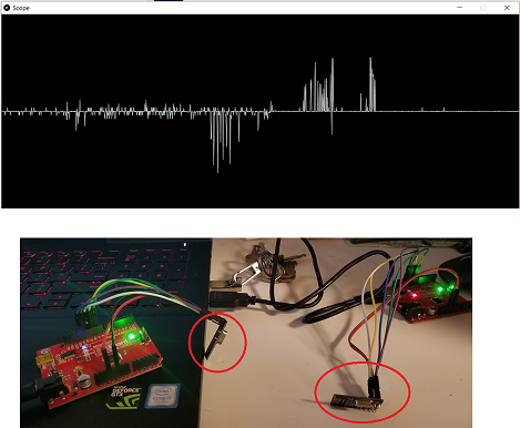
I used this modifed arduino sketch, an ADS115 ADC breakout, and processing, and was able to implement a wireless voltage reading, which I used for a research project I'm working on.
I faced difficulty in porting this from arduino to ATtiny44.
The two options I intially thought of were:
1. Write tiny44 code equivalent to the above sketch, which have the t44 talk to nrf through bit-bang SPI;
2. Change the arduino sketch(pin mapping mostly) and compile it to hex, then load the hex using avrdude.
The first is in fact more insteresing to me. However, given the time constraint, I wanted to speed up the process by using existing libraries, which simplies all the register setting into a few lines of command, so I decided to settle for the second option for the moment.
It turns out that the translating the sketch, which is written for a ATmega328 into ATtiny44 language is not that easy using the FabClass board.
First, to set up serial communication between PC and the t44 requires using a library called softwareserial.h, since the default serial.h does not support t44.
There are two ways the t44 can talk to nrf. Hardware SPI use the dedicated MOSI/MISO pins on t44. Software SPI set up alternative pins for the role of MOSI/MISO, and requires an addition library DigitalIO.h, according to the core RF24 library.
I chose the second opition initially, since I was not sure if the dedicate pins can be used for communication after it was used as ISP pins. I later learned that they can be, but is yet to implement that.
The software SPI requires changing the pin mapping in DigitalIO library and adding to the config file a new pin map header file for ATtiny44. This part has not been successfull as yet. The main difficult I faced is the inter-dependency of this series of libraries, particularly the DigitalIO and its sublibraries. When I changed one variable in one config file, I will always need to account for its scope in another header file, for example, otherwise the arduino compiler simply does not work.
I have not been able to get this work so far.
2. RN4871
Alternatively, I tried setting up bluetooth connection with the RN4871 modules.
Starting with the FabClass board, I made two units and connect them to a PC using FTDI cables. Establishing serial connection to both of them requires serial emulators, which I use tera term in this case. The arduino serial monitor can do the same thing. My goal is to have the two units talk to each other, sending simple things like a character, for starter.
In tera term, I set the serial port according to the RN4871 User's Guide. Here are the paramters:
To set up a RN4871 unit, we need to enter the command mode first. This is done by typing "$$$", and if everything goes well, we should see "CMD>" on the terminal, meaning that we have entered command mode. To make sure we type in the command correctly, I type in "+" to activate local echo.
Next, I set up the service that can do the transfer. In RN4871, the service "Transparent UART" can achieve the functionality. To activate this, I type in "SS,40", where 40 is the bit map for the service. I do this for both devices.
Next, I set the name of the units to be something recognizable by typing, "SN,name", where name is the device name I want the unit to have. I set it to BLE-01 and BLE-02. Setting the name will make it easy for us to find the address in the bluetooth network, to be discussed below.
Moving on, I make one device advertise, i.e. making itself visible in the network, by typing "A". I use the default parameters for A.
On the other device, I activate the scan by typing "F", which looks for all other bluetooth devices in the network. There are two types, connectable and unconnectable. For the connectable type, which our first device is, the response value takes the format: address,type,device name. I find the device by name, and then copy the address.
With this address, without exiting scan on the scanning device, I can now connect to the other device by typing "C,0,address". The "0" here means that the connection is public. Upon successful connection, "Stream_Open" will show on the terminal. Connection can also be confirmed by typing "d", to dump the information of the device, which include the device currently connected to it.
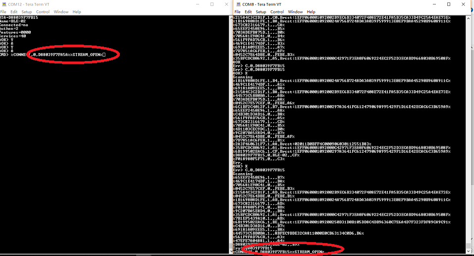
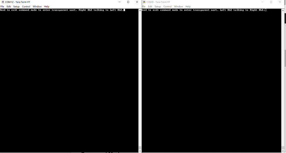
Next, since I have activated the Transparent UART service, I exit the command mode to enter the default data mode by typing "---" for both devices. Now if we type certain character on one terminal to one device, the character will be sent to the other device, which then sends it to other terminal and get displayed.
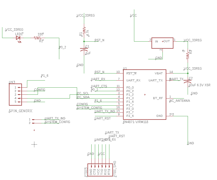
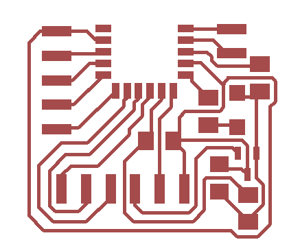
To do automatic mode setting for all of the above, my next step is to integrate it with a microcontroller. Additionally, I want to explore the different functionalities of the pins in the module. Therefore, I made a RN4871 breakout board.
The design went through some iterations, because initially the regulator pinout I created in eagle library is different from the one we have in stock. Correcting that and also making sure the regulator works first, and putting the indicator LED in place only after confirming the RN4871 is talking properly to the PC, I finally have a working RN4871 breakout.
SerialCOM to the chip worked ok and I tried establishing communication between this module and one that Rae has. Everything went smoothly.
Liz and Oceane demo the use of transfer tape and the acetate substrate. An issue occur for the transfer tape, where the copper wrinkle up and take off the adhesive. When this happens, the cut will usually be a failure. In the machine shop, I found a roll of white vinyl-like tape, which may be epoxy film. I thought since vinyl can be cut with no problem, putting the copper on top should be even safer. I decided to make a bluetooth sticker using this tap as substrate.
Using the bluetooth breakout design above, and laminated copper foil on this tape, I adjusted the force and cut speed of the vinyl cutter a few times and find a cut speed of 2mm/s and force of 80 gf to be a good pair to cut out the trace without peeling off from the substrate.
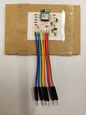
Soldering all the component and jumper wires in place of the FTDI header, here is the final sticker.