Zijun Wei - How to Make Almost Anything
Week 3.
Electronics Production
This week we learned how to use the Roland Modela MDX20 for prototyping PCB boards.
For group assignment, we (Zijun, Elena, Teja and Ravi) characterized the tolerance for the Roland CNC mill.
Using the file here, this is the cutout pattern.
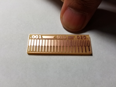
We found that trace pattern of width of down to 0.001 inch (1mil) can still produce a copper trace, the width of which measures about 0.25mm, or 10mil, with a caliper. The resultant trace width begins to match that of the design pattern at around 10mil, from narrow to broad.
In comparison, a gap pattern between two copper pads can only be resolved down to 16mil. A gap pattern below this width does not lead to any copper cutoff.
This gives us a rough idea of how to decide the trace parameters for our custom board in the future.
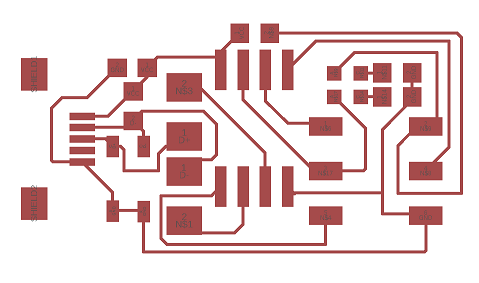
For the individual assignment, initially I would like to make a smaller board based on Brian's design. This is the design layout.
But I ran into some difficult in resolving the traces. The cut out board is shown below, in comparison with the FabISP by Brian.
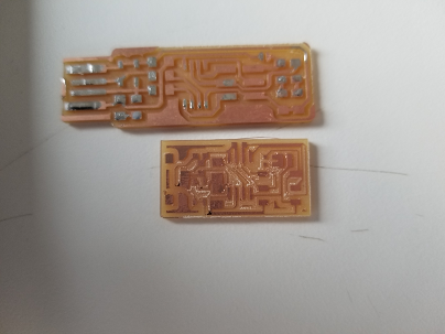
The traces were drawn using eagle with a minimum width of 6mil, which could not be resolved using the 1/64 endmill. In fact some of the traces actually peeled off from the FR1 substrate. This failure to reproduce the result from the calibration test may be due to the more complex movement of the endmill when making board with components closely packed to gether. Additionally, gap between some parallel traces were also not cutout, leading to short.
With this experience in mind, I should be able to adjust my board parameters for future design.
To proceed with making the ISP. I used Brian's design.
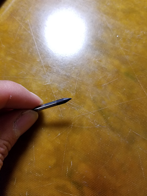
Seems that the double-sided tape could not keep the substrate completely flat, which leads to variation of actual cut-depth. This sometimes can lead to board with short, and at other times can even break the endmill, which happened when cutting out the outline using the 1/32 endmill.
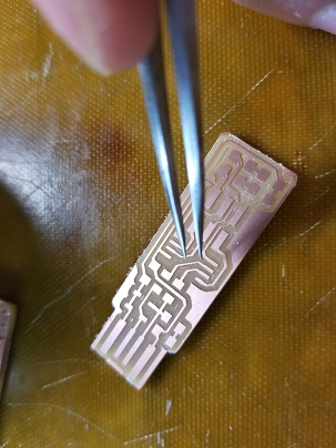
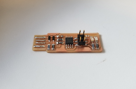
With the board cut out. I proceed to the soldering, which is straightforward, as long as the polarity of components are made clear. The 1206 package components can be easily manipulated with a tweezer.
After soldering comes the programming part.
I'm using a Windows PC and to setup the recommended linux programming environment, I installed Ubuntu and the related AVR components on that subsystem. However, I could not have the subsystem to access usb devices other than mountable drives.
Not wanting to install dual boot at the moment, I installed WinAVR and used avrdude to load the firmware. I do not have an avr programmer, so instead I am using an arduino as an ISP. This required first uploading the ISP sketch and then connecting the corresponding pins according to the specification in the sketch. Additionally, a 10uF capacitor should be placed between the GND pin and Reset pin of the arduino board to prevent it from resetting.
This setup allows me to not only burn the bootloader to the tiny45, which I initially did, but also upload arduino sketches. This setup should also be able to program a third MCU, but the fact that it requires an arduino board as an interface makes the custom ISP redundant, since arduino can pretty much do the same job all by itself. To make a legit ISP, I need to set it up such that it can communicate with my laptop directly.
I wanted to make this custom ISP compatible with arduino IDE, and found this tutorial. I was able to load the micronucleus firmware to the tiny45 after tweaking some parameters and even setting the fuses using avrdude. Concerning burning fuses, it seems that the fuses cannot be reburnt, at least in this method, otherwise the device will be corrupted showing a device signature full of 0s.
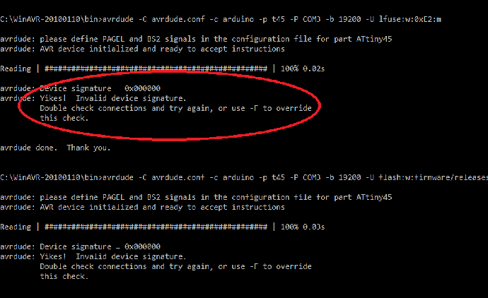
After installing libusb on windows, I expected that I would at least have the microcontroller board recognized by windows, whence I would proceed to using the arduino IDE for setting it as an ISP. It didn't go as plan, as an error message keep poping up showing that the device has "descriptor request failed".
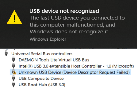
Up till the time of ending this log, I had not been able to solve the above issue. I suppose using an avr programmer or using a USB 2.0 port, which I don't have, may help and hope to find out soon.
Programming ATtiny45 ISP Revisited (10/04):
After discussion with cohort, it seems that the following programming scheme works well with Windows 10 OS.
1. Setting up programming environment:
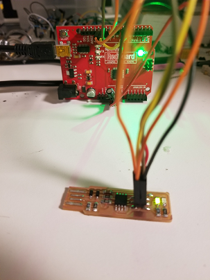
1.1 Uploading the arduino ISP sketch to the arduino board (in my case I was using a Sparkfun redboard, Uno).
1.2 Setting the programmer in arduino to be "arduino as ISP"
1.3 Connecting the pin from the digital and power ports of arduino to the SPI jack, which, by default, should follow this mapping:
Pin 13 --> SCK
Pin 12 --> MISO
Pin 11 --> MOSI
Pin 10 --> RST
3.3V --> VProg
GND --> GND
Finally, place a 10uF capacitor from the reset pin to the GND pin of the arduino board(anode into reset pin).
2. Place the following hex file into the arduino folder where avrdude is located (or if WinAVR is installed, place it at the {WinAVR folder}/bin/, then open command line and cd to that folder.
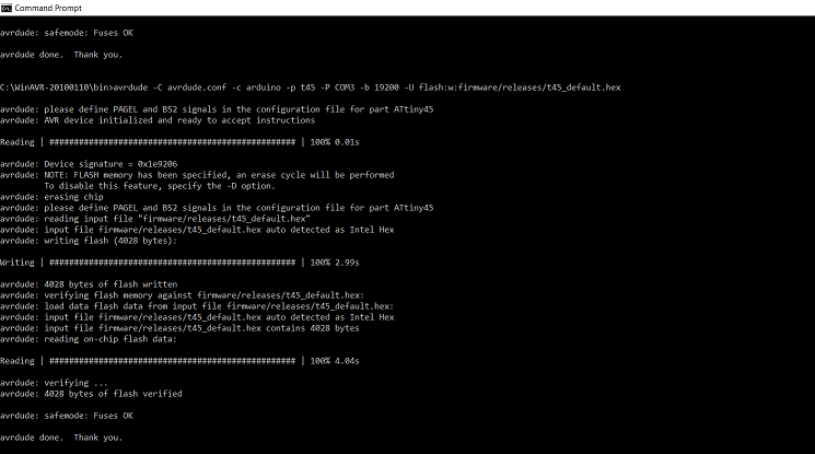
3. Use the follwing command to upload the firmware:
avrdude -c arduino -p t45 -P {COM#} -b 19200 -U flash:w:{folder directory/firmware.hex}:m4. Use the these commands to set the fuse:
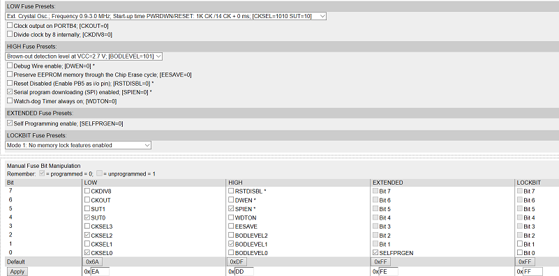
The fuse I initially used was
lfuse: 0xEA
hfuse: 0xDD
efuse: 0xFE
This, according to the AVR fuse calculator, has these specs:
The fuse that Brian used, by inspecting the makefile using this command:
type Makefile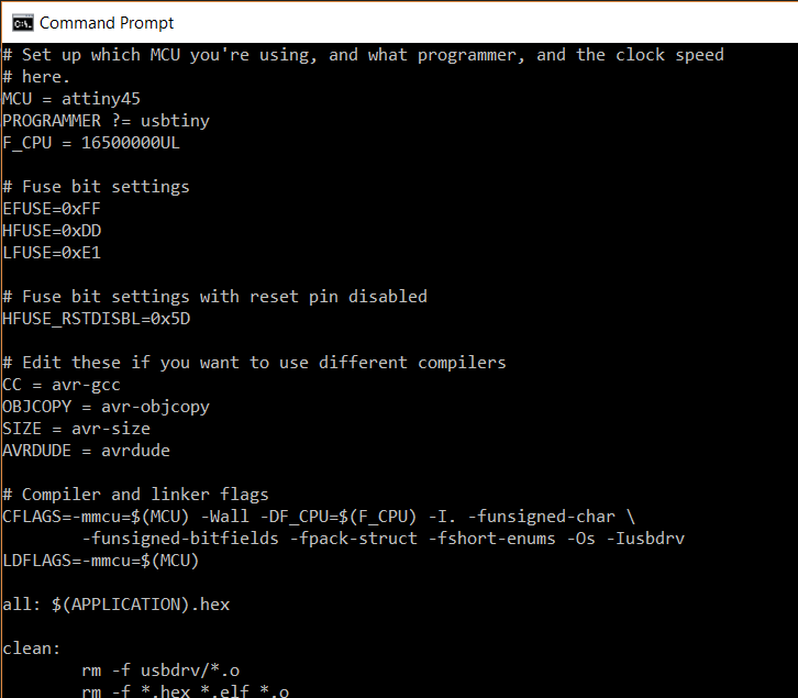
is:
lfuse: 0xE1
hfuse: 0xDD
efuse: 0xFF
and corresponds to these specs:
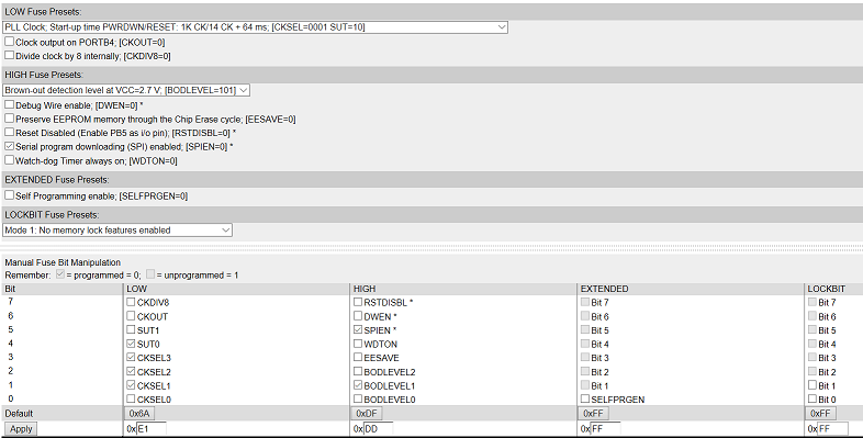
Using this command to set the three fuses:
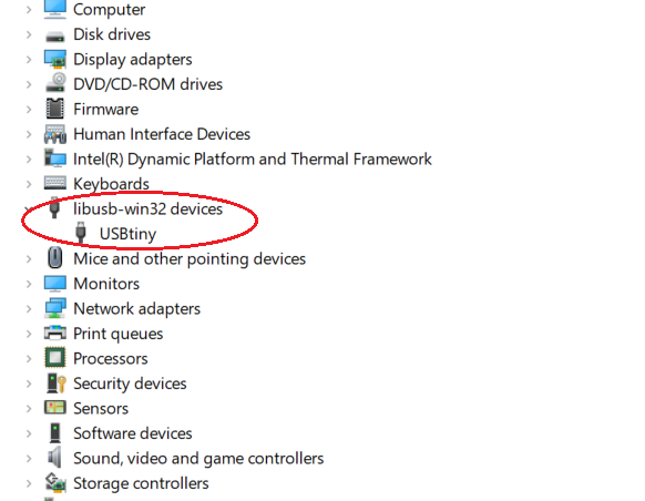
avrdude -c arduino -p t45 -P {COM#} -b 19200 -U lfuse:w:0xE1:m -U hfuse:w:0xDD:m -U efuse:w:0xFFNow, plug the device into the USB hub of the labtop, it should be recognized as a USBtiny device as shown here.
After that, we need to set the fuse again to disable the rest function, so that the chip will not be reprogrammable. This is done by setting the hfuse to be 0x5d. Note that after this, the ATtiny45 will no longer be recognizable through avrdude, as it will show the 00000 device signature as before. (I suppose I may have accidentally disable the reset previously)
Finally, removing the solder from the jumper pin, and we will have a working ISP. Yay!