Zijun Wei - How to Make Almost Anything
Week 10.
Output Device
This week I get to explore the output from an MCU.
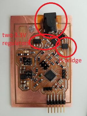
In the test board made last week, I put in an H-brigde chip. This week I will be testing how well it works.
There were some design issues I would like to solved in the previous board, which will be discussed in the project log. Unfortunately, as I tried to mill out a modified board, the 10mil endmill needed to resolve the 9mil contact pad spacing for the gyro chip broke, and I could not get a new endmill in time without spending lots of money. In the end, I decided to do some surgery on the old board.
The original board has two supply, 5V and 3.3V. To accommodate the logic level difference without making a new board, I swapped in a 3.3V regulator for the 5V, so that the board now has two 3.3V supplies. Also, to account for the power requirement, I replace the jumper pins to a power jack, which a power-hub adaptor can fit into.
In the test board, I put in two LED to the INT pins on the H-bridge chip, which flashes when there is control signal coming from the MCU. After loading the PWM code, which is modified from the h-bridge t44 code by changing the pins accordingly, and setting the fuse for external oscillator, immediately, I can see the LED flashing in the frequency of the PWM.
Moving on, I connect a DC motor to the output of the h-bridge. Unfortunately, the shaft is not turning as I expect it to. I could, however, hear a mechanical noise running at the same pace as the PWM. My guess is that the current going directly from the power source to the VBB pin of the h-bridge is not high enough to drive the motor, which is probably limited by the adaptor output, normally ranging from 250mA to 500mA.
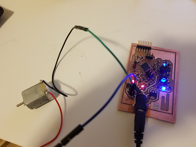
I tested the motor with a power supply, and at 1V, 0.42A, the motor is running fast, meaning it is functional. I also checked the h-bright output pin OUT1 and OUT2. The voltage waveform over time is as shown, which also does not show any abnormality.
Connecting the power supply to the power jack, at 6V, both regulators are turn on, but the current is only 0.02A, which means the motor is definitely not getting enough current.
Later in trying the reference h-bridge board, the same issue occured and it seems that the power supply I used has a compliance setting that limit the current. I believe switching to a different supply should solve the issue.
ATmega328 H-brigde Code