Zijun Wei - How to Make Almost Anything
Week 11.
Machine Building
This week is the machine week. We are to build a machine with given components and materials.
After ruling options such as cake-cutter, flexible circuit-maker and waterpainting drawer, our group came to the initial idea of making a machine with changeable end-effectors, one makes it a simple pen-plotter, the other makes it a chocolate-extruder.
We devided the work into three categories, for three subgroups: machine design and assembly, general electronic hardware and software, and end-effector. Excited to get more hands-on in machine control, I took the lead in electronic hardware and worked with other subgroup members on the software.
The design of the machine is similar to the ShopBot router, consisting of a pair of base rail, the direction of which we call y, for one in-plane (substrate plane) degree of freedom. Another rail sitting on top of that give another in-plane DOF, which we call x. Yet again, on top of this rail, there is a third rail for vertical out-of-plane DOF. The end-effector is mounted on top of this third rail.
The electronics of the machine consists of two parts: 1. Power electronics; 2. Communication modules.
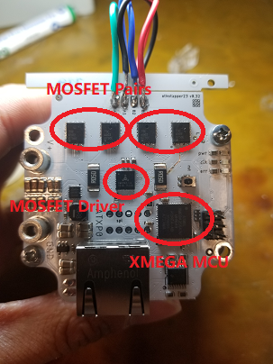
The first part deals with properly powering the stepper moters for the different axes. We are given the automata kits, which include stepper motor driver boards to speed up the process. The driver boards has three major components, a central microcontroller that communicate (takes commands) from the computer through a rounter (to be covered later), a MOSFET driver, and four power MOSFETs, divided into two pairs. The stepper motor has two phases, and each will be connected to a specific pair of the MOSFETs. On taking external commands, the MCU instruct the driver to turn on a certain pair of the MOSFETs sequentially, thus activating the corresponding phase of the stepper motor connected. The number of steps on this level is by setting the value on the timer/counter register on the XMEGA MCU.
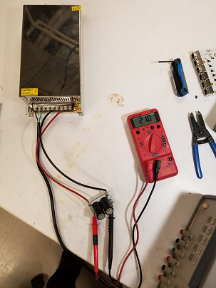
I first tested powering the board through a lab power supply, then uploaded the firmware to the XMEGA use the AtmelIce through PDI using AtmelStudio. Upon seeing the sck led flashing, I was assured that the board has been programmed properly and running well.
Since we will be using a dedicated power supply for the machine, I then moved on to test powering the driver board through that supply. The spec of the supply says it will output 24V, the limit of the buck regulator on the driver board. A mistake I made was that I assume the supply will by default output that value, while I learned later actually was giving out 24.4V intially. This at first gave no issue until I connected it to the router using a RJ45 cable and tested it by sending a move command. Immediately after the command is sent, all the leds, including the one on the power supply went off, indicating a short. After unplugging the power cord. I measured the resistance between the power I/O pins on the board and got a value of a few ohms, which normally should be an overload value. In other words, this fried the board. My assumption is that as the communication command is sent, some voltage surge take place.
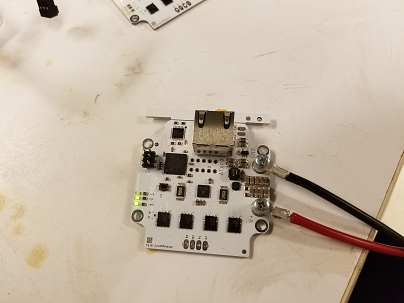
I moved on to test another board, powering the router board through USB only, and was able to have the stepper motor turn with no problem initially.
However, as I disconnected and reconnected the power chords to the wall hub, the above issue occured again, which I think is due to the power spike.
To resolved this issue, 1.I checked the actual output and tuned down the voltage to 21V through the potentiometer, and 2. added a protection circuit with two mF capacitors and a clipping diode, which should smoothen out the power spikes.
Having solved the board frying issue, we were able to program several driver boards, mount them on motors and test the motion.
Additionally, I make a switch between the wall hub and the power supply to ease the application and improve safety. The switch controlls the connection of the wall hub live wire to that of the power supply. In the picture, the red wire comes from the wall hub live wire, and the black wire goes to the power supply live wire. The white wire connect the neutral pins between the wall hub and power supply, while the green wire connect those for ground pins, neither of these connections are controlled by the switch. After all these soldering, the switch is finished by putting in the fuse.
A new issue arose at this point where, for one motor, only vibration occured, and later for another motor, even no vibration, while no signs of shorting issue were found and the motor shafts held firmly when power is connected.
Since the motor is pretty simple in structure, it is less likely that cause of such multiple occurences of the same issue lie in them, given that the ususal way for them to go bad is the burn-off of the insulating coating due to coil heat-up. And the vibration seems to indicate that only one phase of the two is activated. Also, swapping the boards, the motor that initially not worked works. All these suggest that the cause lies in the board. As we are running short of borads, after talking with Jake, I decided to look at the board and see if there is anything I can fix.
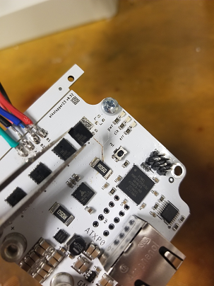
For the board that did not even vibrate, I found that the soldering of the MOSFET driver chip on one side does not seem complete after pick-and-place. Applying flux and a bit more solder, the connection looks much better. However, upon testing, the issue remained and it seems that the traces going to one pair of the MOSFET is burnt.
Assuming that it may tbe MOSFET that is shorted, I replaced the pair of MOSFETs using the hot-air gun. Attaching the board back to the motor, and finally the motor can turn upon receiving command.
In communication, the high-level goal is to send commands from the computer to the motors and have them move in a controlled way. This has been much simplified with Jake's javascript modules on the software side, and the router board on the hardware side.
In setting up the communication, the archtecture looks like this:
The computer send commands to the router through a node server, and the router relay these commands to the respective stepper motor driver boards, which in term controls the stepper motors.
Following Jake's GitLab tutorial, I set up the node server. In having the router talking to the driver boards, I made the RJ45 cables and solder the corresponding cable jacks on the boards.
The test on controlling the movement of separate motors has already been covered above. After mounting the motors on the assembly, we tested the movement of the machine on the different axes. The key is to make sure that the command is send to the right address on the router board. This address is defined by the second number in the route box. Making sure the the mapping is correct, we sent a test move command to the x and y axes and the movement went pretty smoothly.
We did not initally test the z axes until the end-effector was mounted. The extruder was heavy, in fact to heavy to be lifted initially using the inital stepper motor:
The motor tried to lift the parts, but gave up in the end.
It seems that the causes are two folds:
1. The stepper motor is not powerful enough to handle the weight of the end-effector
2. The convey belt was not tightened enough, which sometimes leads to slipping
To solve this, I swapped out the original motor with one that has twice the coil size, which Fillipos found in the CBA stock. We also tightened the conveyer belt and make sure the grip is good.
This solved the issue perfectly.
In controlling the extruder as a whole, we need to control three degrees of freedom for the end-effector movement, plus the extra degree of freedom for the extrusion, since it runs in a syringe mechanism.
While control of the x,y,z movement can be easily implemented by sending gcodes to the node server, adding an extra degree of freedom for the extruder requires tweaking the gcode parser. We were not able to modify the javascript to allow gcode reading on an extra degree of freedom with the time given. Instead, I changed the mapping to the z axis driver to the extruder driver, so in effect, we achieved a 2D chocolate extruder at this point.
Besides optimization, future work will need to modify the javascript to achieve a 3D chocolate extruder.