Zijun Wei - How to Make Almost Anything
Week 9.
Input Device
This week I get to explore different sensors for input into the MCU.
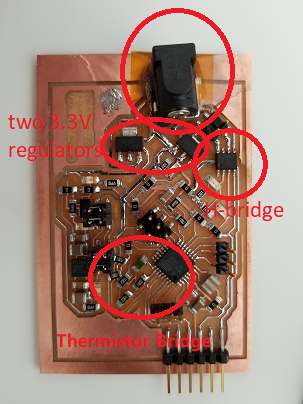
These are to the MCU what sensing organs to a brain. I was excited to try out all the sensor components in stock at 043, but given the time, I only chose a few that I think I may need for my final project, which are laser-distance sensor, gyro, and accerlerometer(not chosen for this week). The crammed-up board will be dicussed in details in the project log.
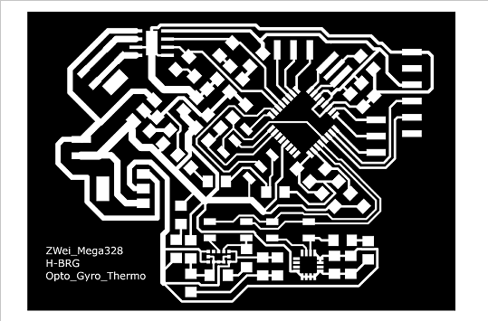
But as a quick test of board integrity, I uploaded c code for mega328 to read the thermistor value. ATtiny44 has the function of doing differential measurement, but ATmega328 does not. Therefore I just did single-ended measurement and compare it to half of the Vcc to estimate the temperature.
Besides the above modalities, I am also interested in trying other varieties. For starter, I would like to try synchornous detection.
Specifically, I am making the synchronous detection board through optical modality. In a nutshell, it works like this. A blinking LED will serve as an illumintor to objects in proximity. A phototransistor will pick up reflected light from the objects, which will also be contributed from other light sources. To determine the distance of the objects from the board, only the light from the LED will be selected as the signal through the features in frequency. The intensity of this LED light from the objects, is determined by the distance of the objects, which can thus be deduced.
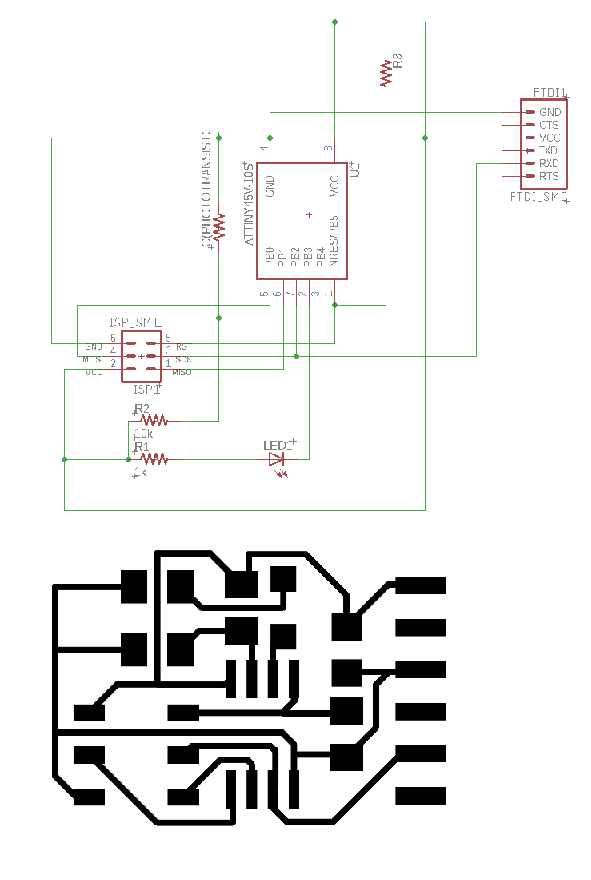
I redrew the hello.reflect.45 board. After milling and placing the ATtiny45 and other components, I flashed the board with the hex file generated from Neil's code.
I initially used a green LED, which gave no significant change on the python terminal GUI. I thought it was a wavelength mismatch. As I checked the datasheet, the operational spectrum for the phototransistor I chose is actually sensitive in IR range and has cut-off at around 700nm.
Later I learned that the original board was using OP522, which can cover visible red. I swapped in the phototransistor and a red LED, and correcting its orientation after failing to get the expected response, I was finally able to get the detection working.
A comment on the red LED + OP522 board: the detection works best when the ambient light intensity is low. In my office desk, which is next to a glass window, I could get a much stronger response at night than in the day time.
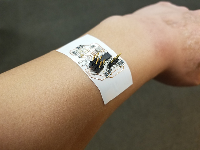
As I later learned the skill of cutting copper trace with the vinyl cutter, I also tried making flexible board, using a layer of copper sheet on epoxy substrate.
I was testing out capacitive sensing, as a possible modality for capturing hand gesture for my final project.
The reference board by Neil runs smoothly with the python code, giving significant change in the intensity bar when my hand is over the eletrodes.
To test for my final project, I chose ATtiny44 for my board, since I would like to able to read multiple channels in one module. The notion of channel here refers to the capacitance between the charging/discharging electrode and one electrode whose voltage I measure. As a simple starter, I only have two reading channels. The principle of this type of sensing is that, with two electrodes connected to the microcontroller, one sequentially charges and discharges one electrode, and measure the voltage on an adjacent electrode. The voltage change on the second electrode at a given time after the charge/discharge is inversely proportional to the capacitance between the two electrodes.
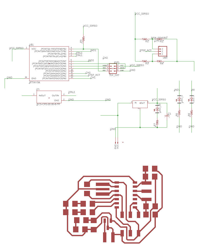
I used a 20MHz crystal for timing. As an indicator, I used two LEDs to show whether the capacitance has pass a certain threshold for a given channel. When the capacitance is beyond/below a certain threhold, the corrsponding LED should turn off/on.
The schematic and traces look like this. I only learned later that since I only have one remaining pin, I will not be able to establish serial communication between this board and a PC, making debugging difficult. There is a foot print for a 3.3V regulator, which is from my inital design goal of also including an accelerometer, to be included in later design not covered in this log.
After making the board and assembling, I connected the channels to two copper electrodes laminated on a glass slide.
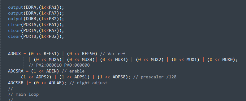
From the data sheet I use the following register setting. They mostly concerns the ADC channel and reference voltage selection, as well as the mapping for output pins and ADC reading pins.
ADC and pin setting
After the modified code is loaded, I tweaked the value of threshold to see what stays in the middle between the capacitance values for "max" and "min" states. That was the initial idea, which turned out to be not very effective. Sometimes I did get an on LED when hovering my hand over the two electrode, but that is not very consistent over time.
Since I have no serial port, I cannot debug the board like I did with previously ones through serial printed values. In the future, I should at least leave the serial communication option open for software debugging. This sensing modality will be something I will continue looking into toward my final project.
That being said, such sticker board is fun to play with and probably a low-cost alternative to the cleanroom-made epidemal thin film sensors.