Final Project
Sting (The Sword of Bilbo/Frodo)
For my final project, I decided (for now) to try and make a replica of Sting, an Elven sword wielded by Bilbo and Frodo Baggins. Sting glows when orcs (or goblins) are nearby. Although I do not know of any nearby orcs, I do hypothesize that seeing an orc will lead to a sharp jump in skin conductance (EDA). Therefore, my plan is to make a sword which glows up as response to EDA peaks.

Why? it’s neat, funny and will allow me to use most of my newly learned skills as well as deepen my understanding of measuring bio-signals and quantified self.
The Plan
My project is contrived out of 3 distinct parts, which will have to be assembled:
- Blade
- Electronics
- Handle
The Blade
The molding ad casting week really inspired me for a cool design which I think should work. I am excited about bio-inspired technology and design, so my plan is to incorporate natural elements (leaves, branches) into the blade, which will also make it look more Elvish.
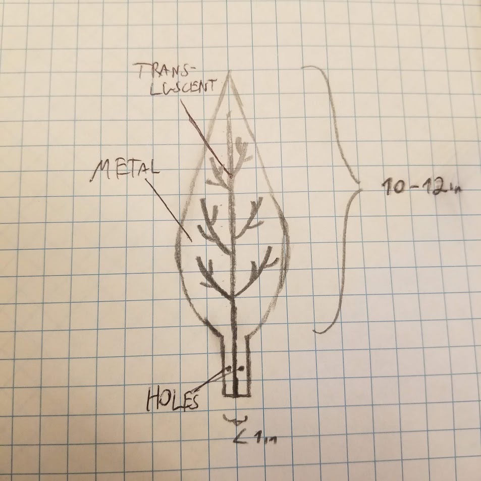
The blade size I’m thinking of is 12 x 4 x 0.5 inches
The plan is as follows:
- Mill a inverse mold of the blade (without the insets) in wax (I need a 12-14in by 6-8in wax)
- Find a natural element (branch/leaf) that fits nicely
- Put the branch/leaf in the was, glue it, and put OOMOO in the to create a soft copy of the blade
- Copy that using OOMOO/Max Mold to create the final mold
- Cut out the natural inset pattern from the first mold
- Pour metal into that mold, and use the cutout on top (so we get insets on both sides)
- After the metal part is ready, need to pour some translucent material into the ducts which will stick. Maybe dip it all in resin?
Open questions:
- Which metal to use? Cerrotru?
- How much metal do I need? How much will it weigh? calculate stress on the handle
- How to keep it bubble free?
- Is two holes enough to keep it tight to the handle?
- How long does the part that goes in the handle should be?
Alternative plan - design everything in CAD and make it. Maybe use some cool mathematical function to create natural looking patterns.
Update: I eventually decided to abandon the leaf shape and go for an authentic replica which will be cast in crystal resin, with an inner duct where LEDs will pass through.
Electronics
I want the sword to glow as response to EDA changes (skin conductance). I consulted with Abhi from Fluid Interfaces, and it should be a fairly simple circuit (step response as input):
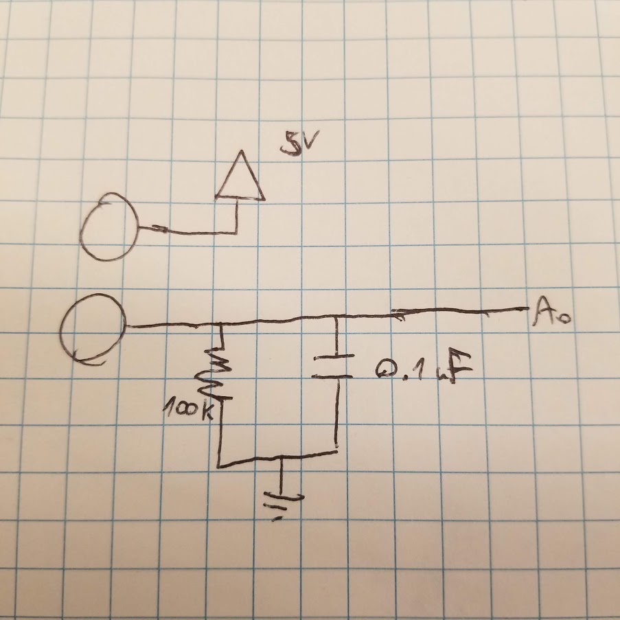
For electrodes, I will start with two copper vinyls which I can wrap around the handles. The electrodes will be connected to the board by two wires, which will slip out from the inner side of the handle to the outside (where the copper will be)
There will be code running on the microcontroller that will sample EDA, calculate differences, and translate large differences (bigger than some threshold) to light.
I am a bit afraid that EDA will not work as expected, so I though to add to my circuit an accelerometer too. And using a switch button, the sword will have two modes - glow on sharp EDA changes and on sharp movements.
The board will also have LED output, preferably blue.
Open questions:
- How to design a board with pads for LEDs so I can play around with them.
- How do I design a strong light output?
- Which microcontroller to use?
Handle
The handle is the final piece that will make everything fit. It needs to have a way to tighten the blade to it. And a slot for the board. And two holes for the electrode wires.
I need help on how to design this. I am thinking to 3D print it, or maybe mill it for wood. It will probably by two parts and a cap. Something like:
Open questions:
- How to properly design this??
Electronics and Programming
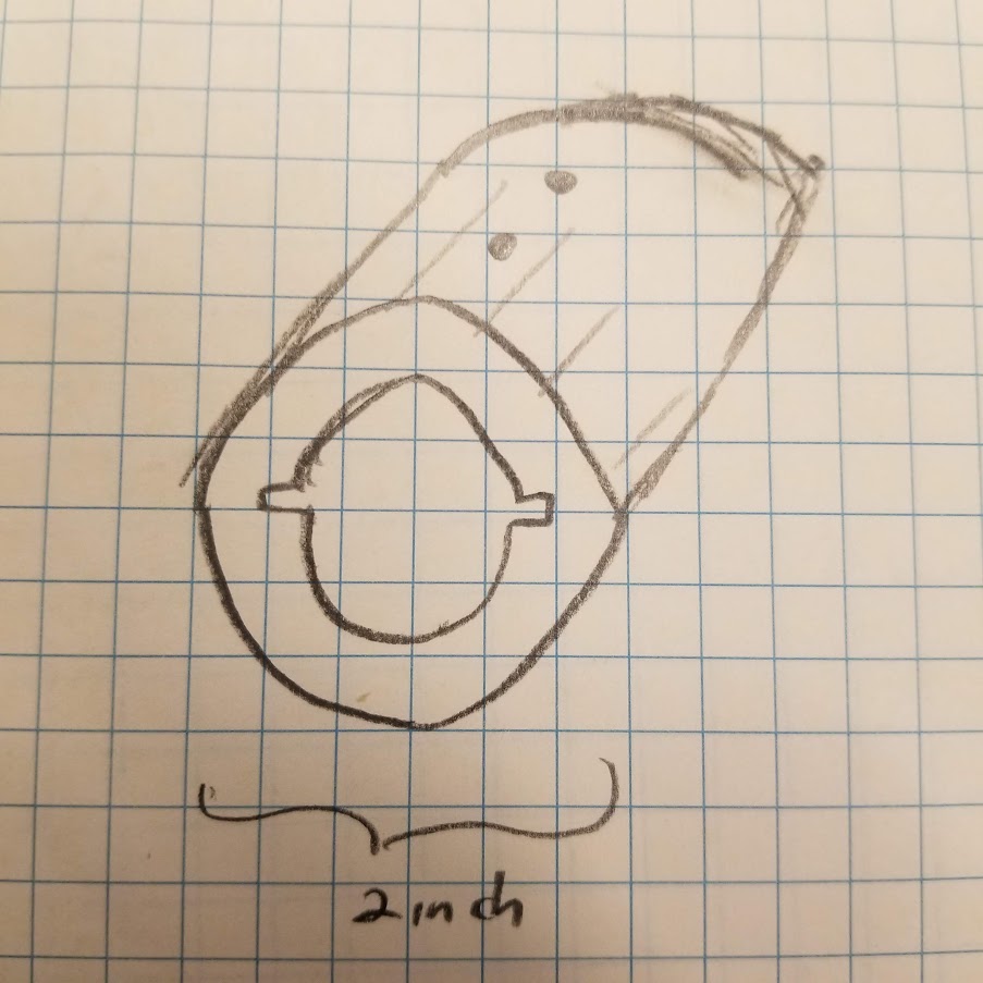
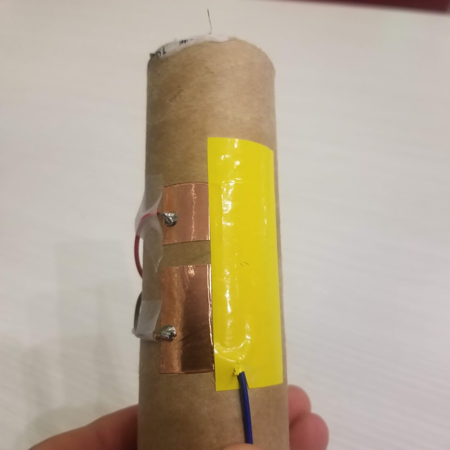
On week 9, I started working on the input device for the project - an electrodermal activity (EDA) sensor to detect fear. I created a simple prototype by sticking copper electrodes on a cardboard tube. To test it, I had to watch dozens of scary videos on youtube. It’s interesting to note that I notice the sharpest EDA jumps on the first time I watched a specific video, compared to consecutive viewings.
While it worked well, as you can see here:
The signal was very sensitive to pressure changes. Therefore, I decided to try and make something more interesting. In class we learned about using step response to sense pressure. If I could receive as input two signals - EDA + pressure (without EDA), I could use that to calculate a normalized EDA signal.
On week 10 I designed a new board, that can receive input simultaneously from a load sensor (copper sheet that is charged and discharged) and EDA sensor (two copper sheets, one connected to 5V and the other is sensed). This board can also control an arbitrary amount of Adafruit NeoPixel LEDs, so it might be a final design (just have to take out that pesky FTDI header).
My test setup is as follows: on a cardboard tube, I glued two exposed copper sheets about 1 inch a part. Next to them, I glued a longer copper sheet and added a vinyl sheet on top of it to prevent any skin conductance.
I modified Neil’s Python app which displays the raw signal from the board. Following Neil’s code, I applied an exponential filter to get a smoother signal.
(Side note: how to easily insert LaTeX into Jekyll)
I was happy to see that the two signals - Pressure and EDA to seem to have a nice linear correlation.
I am not really interested in the values themselves, but the their first order differences. These can be quite noisy if I calculate them sample by sample. After some experimentation I decided to go for the following calculation, for :
Now, to calculate a Fear Score, I wanted to use these two numbers. The loic is that they are negatively correlated. But, when EDA goes up in an uncorrelated way compared to Load, that’s when Fear is kicking in. I watched too many scary movies as I experimented with these formulas. The best two approaches I found were:
- Use Least Squares on a set of measurements (calibration) to get the 2 parameters (slope and bias) that tie and . Formally, we find the best and to solve:
For
I use these parameters to predict a new measurement and calculate the residual error.
I also tried a normalized version of by dividing the average residual error of the model.
- Hand crafted formula:
Which encapsulates what I wish to achieve. The squaring is done mostly to amplify it, as according to my experiments, small changes (1-3) are miniscule but 10 is very significant.
While (1) seemed to have more solid ground, it works well when there is constant pressure variance. But when the hand is very still, the solution is super sensitive and the Fear Score explodes. (2) proved to work quite well and could be easier to implemented on the device. I’m still interested though to see how to run least squares on a 8bit microcontroller. The benefit of that would be that I could follow the current industry trend and promote my sword as AI powered. Anyway:
(Sadly the audio was not captured and I’m too afraid to produce more videos by now)
Python Code (will later re-implement in C)
load_filter = (1-load_eps)*load_filter + load_eps*load_value
load_diff = load_filter - np.mean(last_loads)
// push to last_loads and pop the oldest element
last_loads[:-1] = last_loads[1:]
last_loads[-1] = load_filter

eda_filter = (1-eda_eps)*eda_filter + eda_eps*eda_value
eda_diff = eda_filter - np.mean(last_edas)
// push to last_edas and pop the oldest element
last_edas[:-1] = last_edas[1:]
last_edas[-1] = eda_filter

norm_eda = max(0, eda_diff + min(0, load_diff))
fear = 4 * norm_eda *norm_eda
The Sword Blade
I decided to let go of the option of casting metal due to price and compllexity constraints. I realized that just for one test I will need a few blocks of Cerrutro where each of them costs 15$.
So instead, I have two plans. Plan A - mold and cast a sword blade from transluscent material (Crystal Clear). Plan B - 3D print the blade.
Plan B is more safe to execute but requires me to print in parts and combine them (since the Prusa tray is too short), so it will probably look less cool. So let’s keep it as a backup option.
Blade - Modeling
So plan A. I tried to find an actual 10-15 inch sword so I can cast a mold straight from it. Alas, none of my friends had one, and I even went to the MIT forgery and saw a perfect one on display but couldn’t grab it legally. So, the path is to for 3D model a blade, mill it, cast a mold, and cast it with crystal resin. I have no 3D design talented, so luckily I found a beautiful 3D model of Sting online, surprisingly for free.


However it was a bit too long and too thin to occupy the electronics I had in mind (more on that later) so I opened the file in Blender, scaled it and extruded it to be around 1nch thick and 14 inches long.

Blade - CNC Milling
Then, off to the ShopBot desktop with a piece of 2inch pink foam that is very cheap and was just lying around the shop. I decided to do a very fine finish cut with overpass of 10%, which turned out quite nice.

Blade - Vinyl Cutting
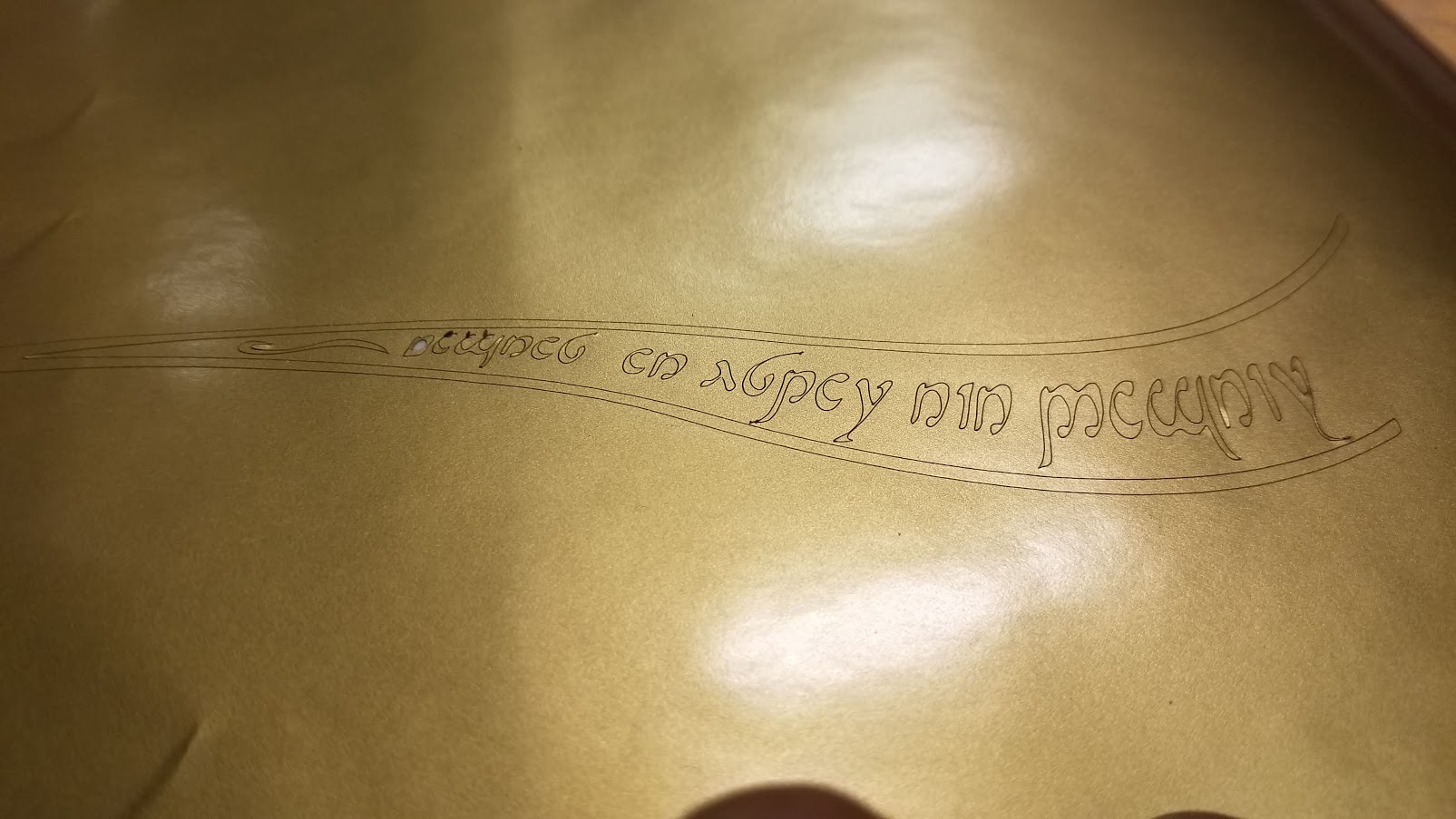
In the original books it’s not clear how Sting looked like or if it had any engravings, but in the Peter Jackson’s movies there’s an engraving in Sindarin, an Elvish language:

Which is read as
Maegnas aen estar nín - dagnir in yngyl im
And translates to
Sting is my name, I am the spiders bane
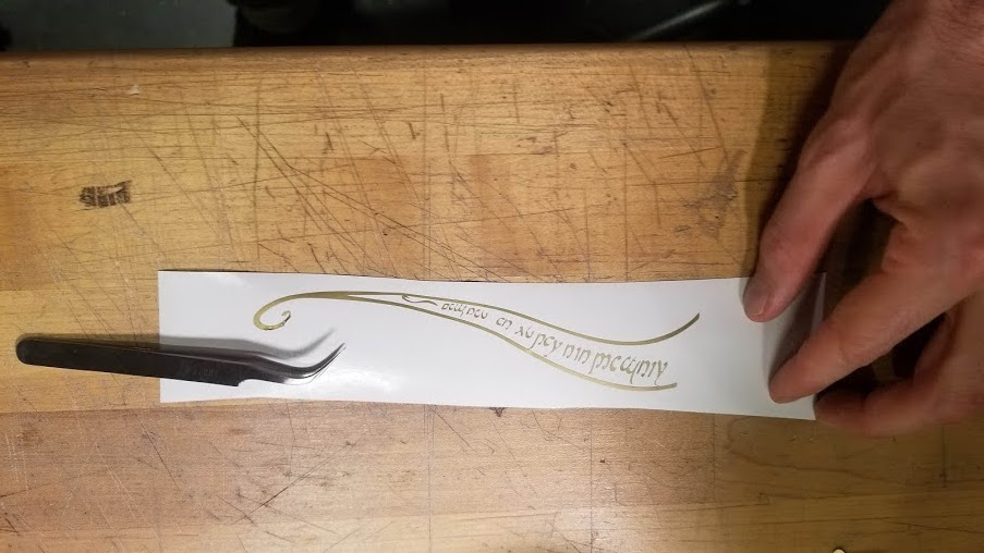
The foam has a rough texture which I hope will give a nice diffuse to the crystal resin. Then I had an idea. My original intention of using leaves and natural elements in the casting process was abandoned, I was curious how it would like like if I vinyl cut this Elvish engraving, stick it on the foam, and let Mold Max copy the different in textures. So, off to the vinyl cutter, I took the texture file from the same link above and extracted only the engraving and its leafy outline into a black and white high res image using GIMP. Then on the Roland, it took me a few tries since the details are very fine.
Some say the Sinadrin cannot be tweezed by man. I wish I was no man so I could have a nice reference here.
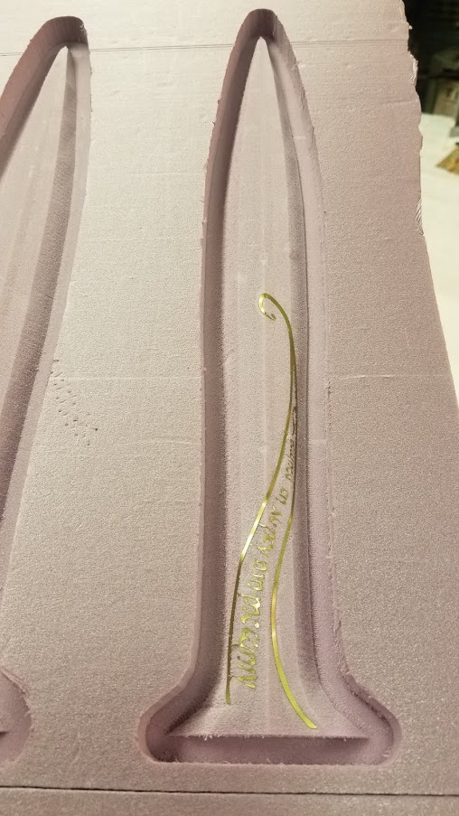
Blade - Mold Casting
To make a mold, I used Mold Max 60. Graham suggested I use it instead of Oomoo because of the size of my blade, and we also have a lot of it. I hoped to get it bubble free on the first iteration. So I put extra care to vacuuming it, and puring it very very slowly and in a thin drizzle. The mold turned out well, wlthough the Elvish vinylid not transfer to the mold as nicely as I hoped, oh well.
Notice the mold got the rough texture of the foam, but that’s OK as I hope it will create a nice diffuse texture on the clear resin.
Blade - Resin Casting
So far so good, but here is where things go wrong. First, I needed to plan two things for my case: 1) The blade should have an inner tunnel, where LEDs will pass through. I have bought 100 addressable button LEDs for 15 cent per LED (and shared those with the rest of the How to make gang). The dimensions of those are 1cm x 1cm x 0.3cm. Theoretically I could cast the LEDs straight to the resin (maybe I will do that later). But for debugging purposes I prefered to have a tunnel where I could slip them in (and out if something breaks down).
I got some crystal resin from awesome Nina:
I first thought to laser cut acrylic that will be set over the cast resin, but then helpful Tom suggested a nice hack that i could just use one of the metal rods lying around. To prevent the resin from stucking to it I borrowed this transparent sheet from wise Alfonso, who also consulted me on my second problem. I need the handle to hold the blade somehow. I eventually thought to just cast to set screws and hope that thhat will be enough to hold down the blade without it cracking down.
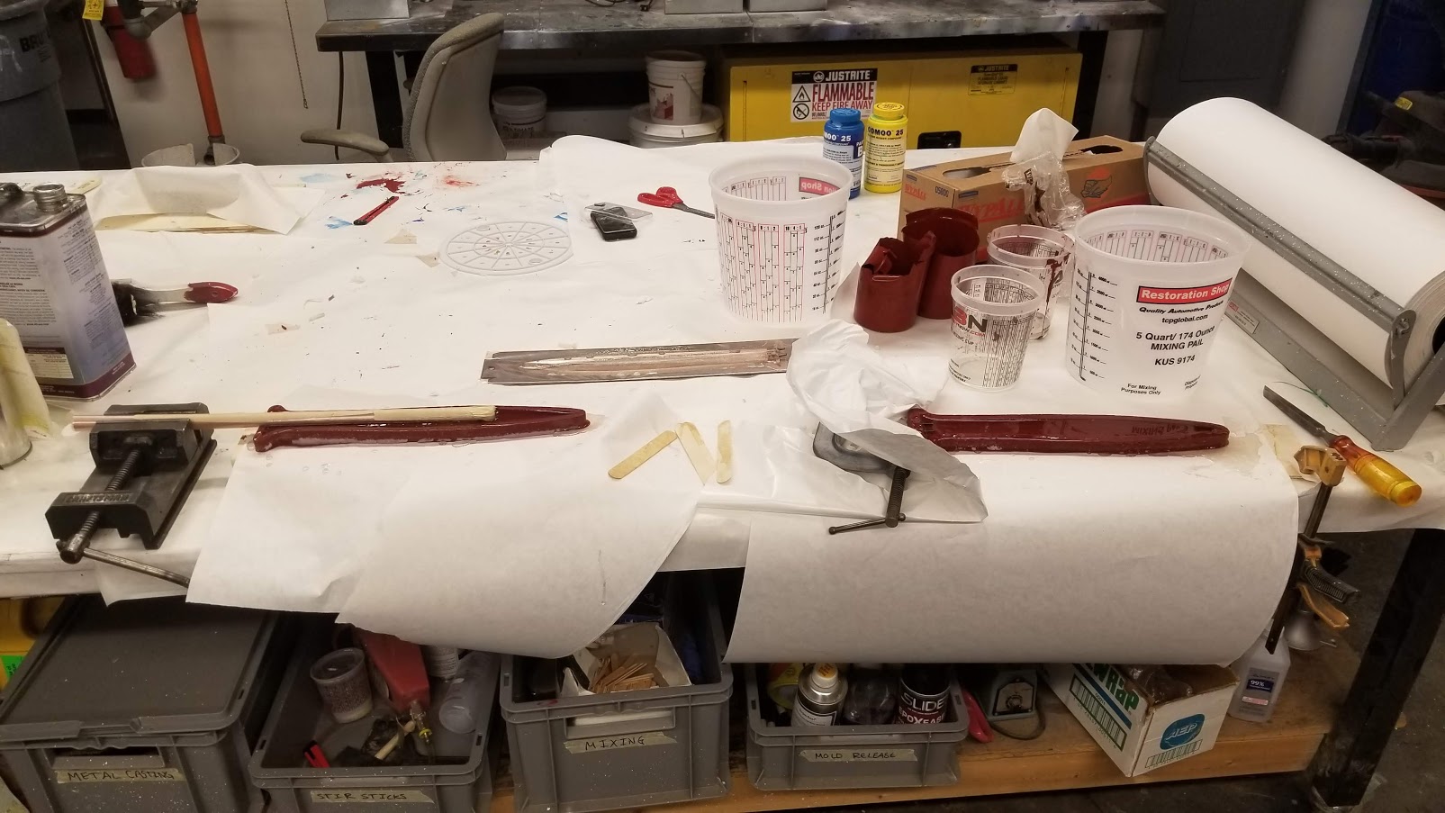
So when the whole setup was prepared, and it was time to cast… I did two stupid mistakes. On my first cast, I didn’t ready correctly the mixing instructions. For different widths of material, there’s a different amount of drops of catalyst to be dropped. I didn’t notice the number was per ounces so I mixed 3 times less than I should have. Damn. Luckily, after 1 hour the resin was already solid enough and the release agent did a great job so I could just pull off the piece and cast a new one.
For my second mold, I got the mixtures right, but I forgot to put a release agent… let’s see how it will work out tomorrow. I read that some heat should help.
The third one is supposedly good. Let’s see tomorrow.
And…
……
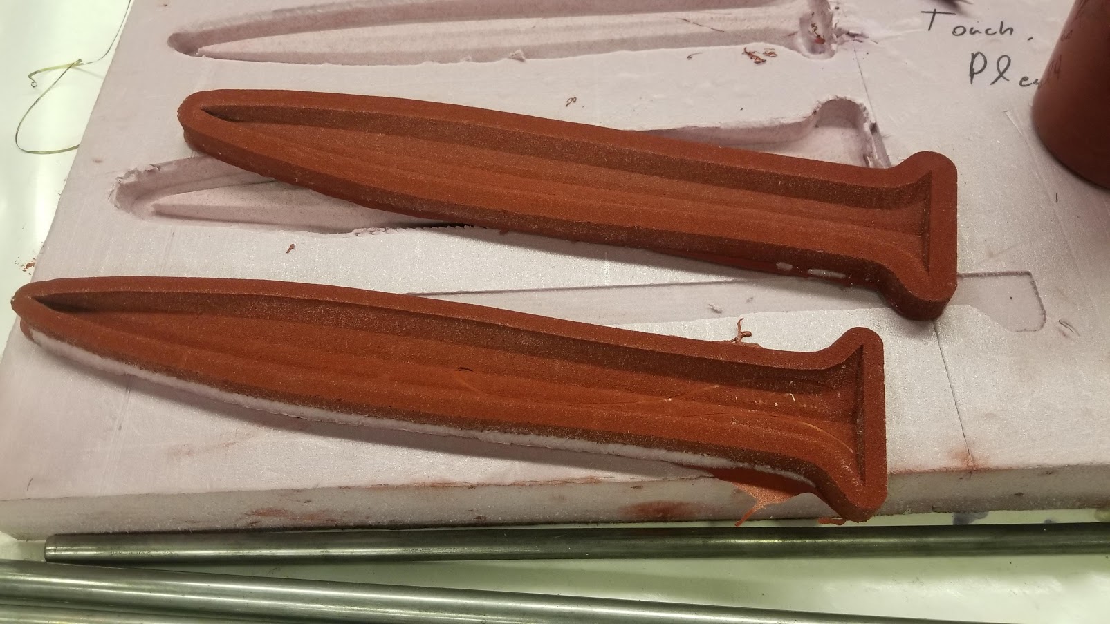
It worked quite well!
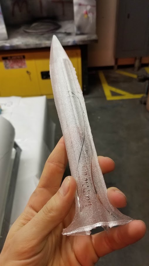
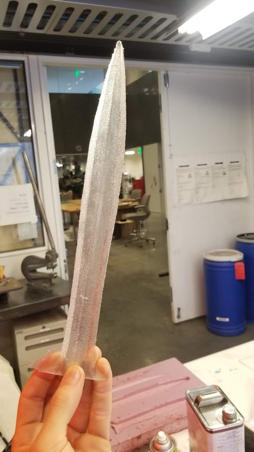
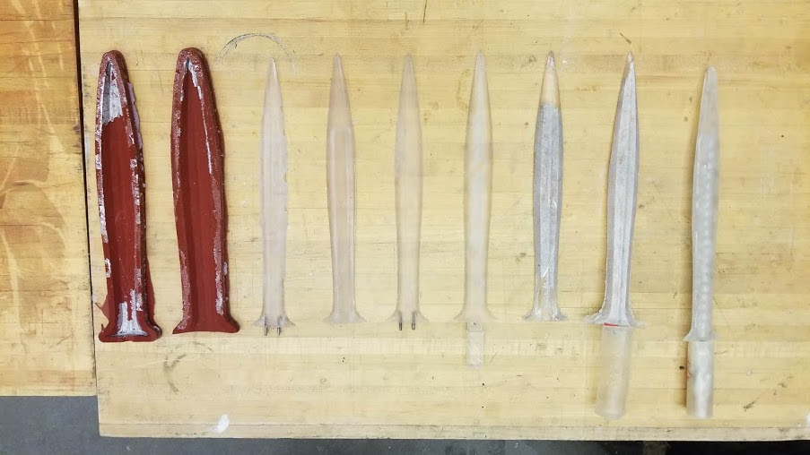
It seems that that Mold Max doesn’t require a release agent with this resin, as I could just pull it off. Knowing that I can pull of a mold after just a couple of hours, and cast a new one - I suddenly had a much shorter experiment cycle, which allowed me to experiment with a bunch of designs on how to connect the blade with the handle.
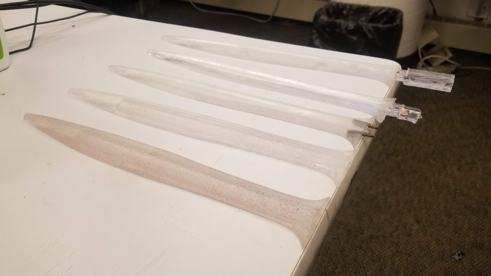
Quite quickly I came to the conclusion that my origin design of blade only is problematic, so I extended the resin so the handle can grip it somehow. More on that later on handle design and 3D printing.
And here are all of my iterations and casting attempts:
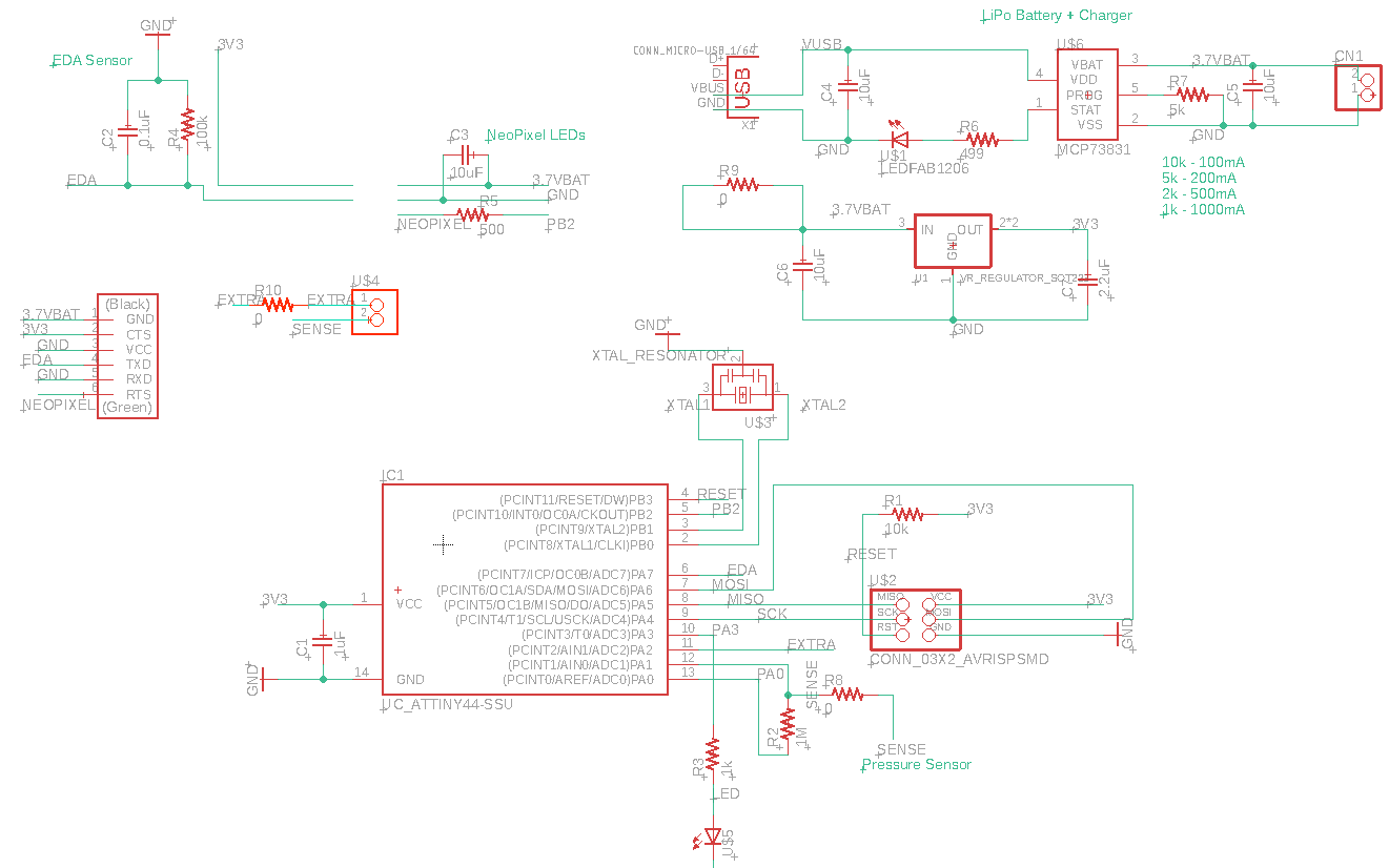
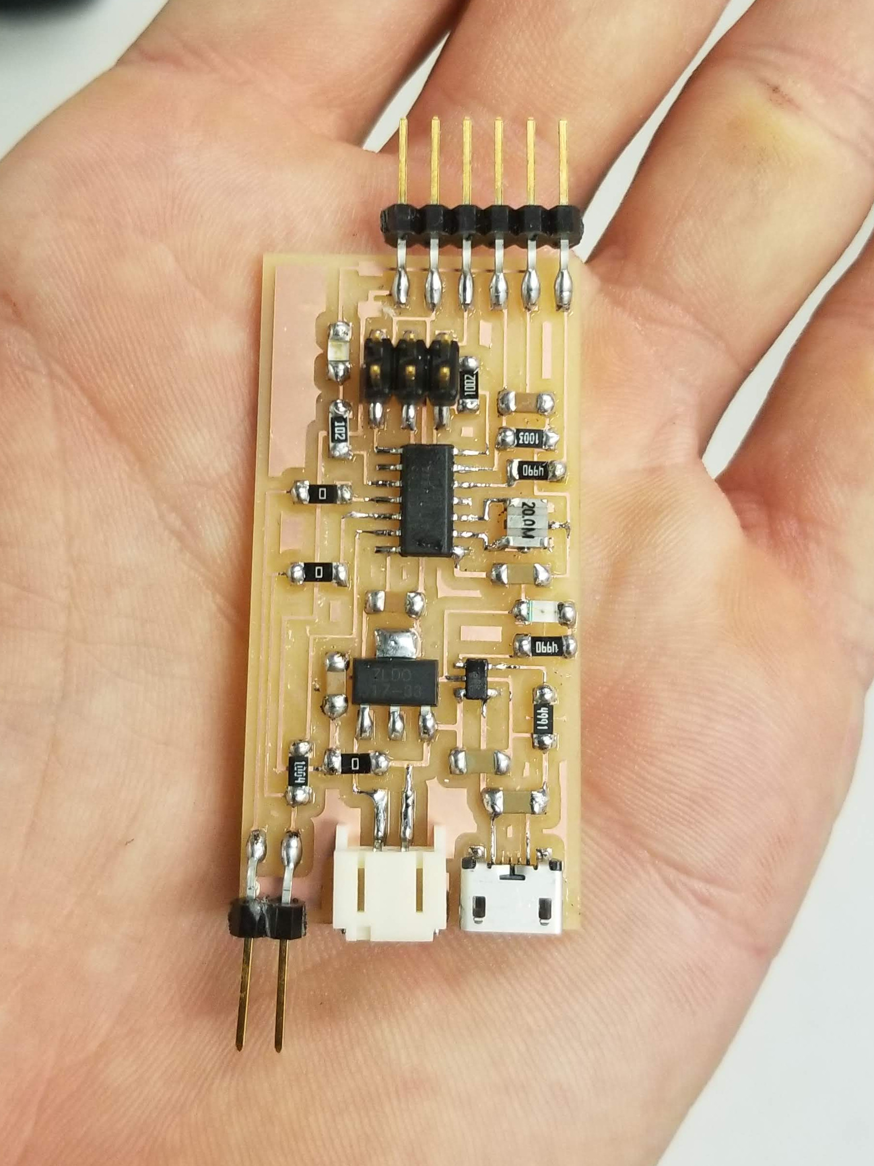
Electronics - The Final Board
For electronics, I already had a board that did exactly what I needed from week 10. I needed just to added a battery so it can be totally portable. Since everything needs to be packed in a small handle, I chose to use a LiPo battery. Tomas helped me design a circuit which contains the battery, a micro USB charger (so the whole thing can be plugged and charged! cool) and a regulator so the sensor voltage would be constant (apparently the LiPo batter doesn’t give out constant voltage). Here is the new power part for the circuit:

I also wanted to re-design the board so all the pins would be horizontal, except the ISP header which I can just pull out once it’s ready. So the board traces did had to be re-designed. Following Neil’s advice, I tried to put the Load Sensing pin far away from stuff, although in such a small board that’s kind of hard…
And the traces:
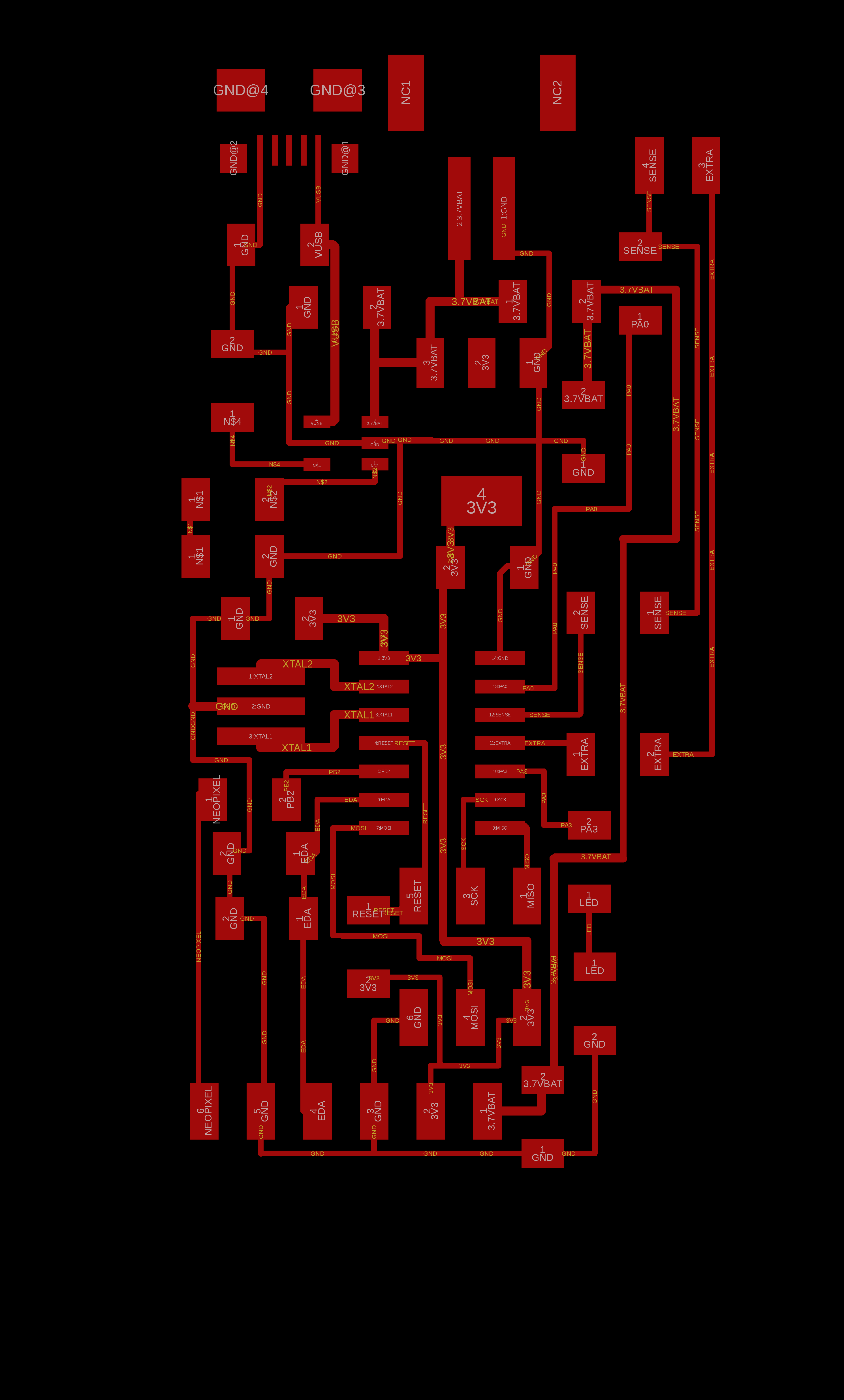
The milling machine did a fine job for the last time (in this semester):

And after careful, calm soldering:
 (Thanks Tomas for helping me out with soldering the microUSB)
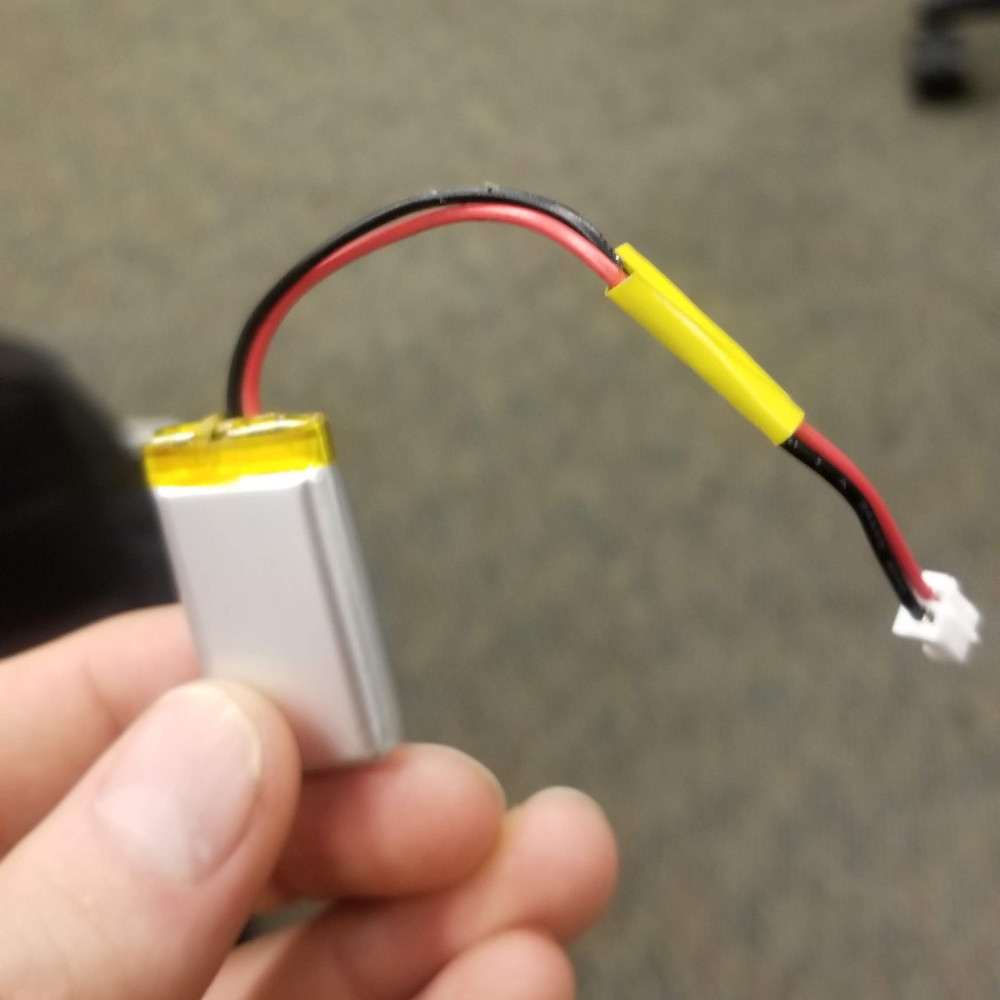
The board was working an programmable, but only when connected to USB. My 350mA 3.7V LiPo battery didn’t work. After some debugging, I found out that the footprint I used had the wrong labels - GND and V were mixed up! I don’t know how come this didn’t fry the board… but luckily it didn’t. To fix it I simply cut the battery and switched the wires:
Electronics - Luminescence
The swords needs to glow. I researched a bunch of different ways to achieve a nice inner glowing effect:
1) Backlighting - the idea is that the blade will be translucent and a strong light source from the handle could light up the whole blade. I managed to get my hands on a bunch of optic fiber side glow cables. Basically its a cable whose core is very clear but the sides to emit a bit of light.
I decided to not go down this path as it would require extreme craftsmanship on the blade casting part, as well as a powerful light source, which means a powerful battery and so on.
2) Electroluminescence - In this technique, current is being transmitted through phosphor:

EL wires and strips have become very popular, especially in festivals (it’s even called the “currency of Burning Man”). I played around with the idea of creating one myself, perhaps by following this nice video tutorial. However, once I realized the scarcity and price of phosphor, I decided not to. I did buy a bunch of EL stuff (wires, panel, strip) on Amazon to experiment with.
You can scissor cut the strip/panel to different shapes, and just make sure to seal it tight. The main difficulty with connecting it to my main board would be the power - it requires AC, inverter and things I have yet to fully understand. Definitely possible. But under time constraints I decided to go with the third option…
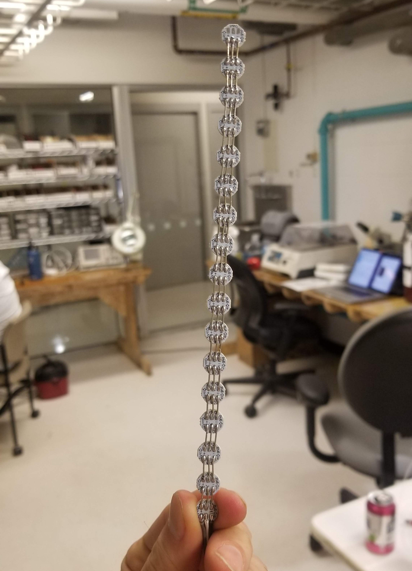
3) LEDs! not just regular LEDs, I went for addressable LEDs. These are components that can be chained together and a microcontroller can address each LED and set a specific RGB value. A very common protocol for this piece is WS2812b, well known as the architecture of Adafruit’s NeoPixels line of products. The shop doesn’t have these, so I paired up with Emma and we bought together on Amazon a cheaper pack of 100 “button” mini LEDs. Each LED is 15cent. Cool.

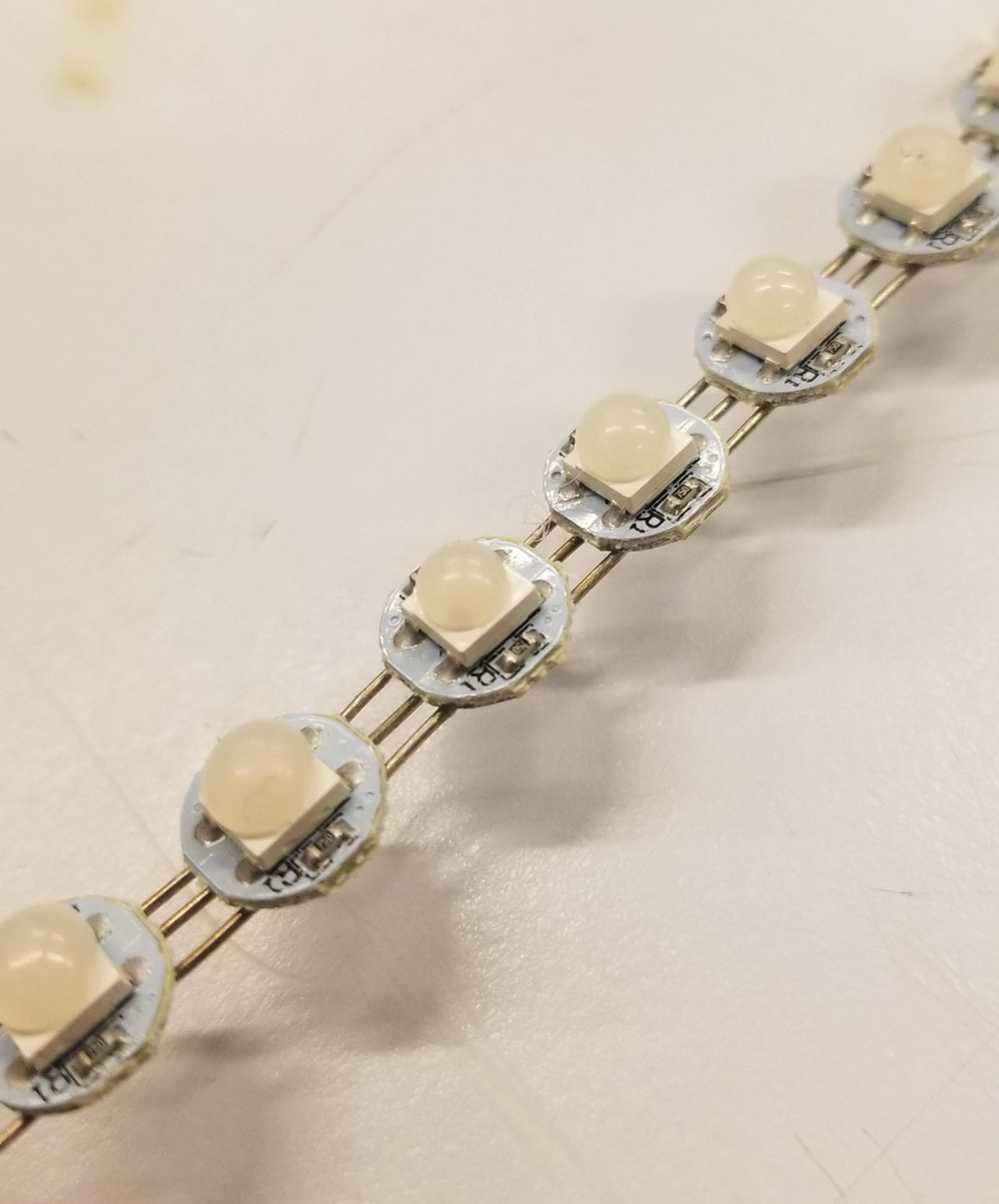
In retrospect, I could have bought a LED strip and save myself precious soldering time. My original intention as to prepare a string where one LED is up and one is down to have the word both ways. However, once I experimented with the actual LED and crystal blades I noticed it looks nicer (at least in my opinion) t have all of the LEDs facing the same way. So I soldered 17 LEDs together:
Another thing I noticed is that these LEDs are very strong, and very “pointy”. It’s hard to take an image of this, but you can really see the point of light even bhined the fossy crystal blade. I thought how to diffuse the light better, and eventually discovered a really cool hack - a drop of hot glue on each LED, to get a much nicer diffuse:
Before I show how it all came together, let’s get down to the code…
Electronics - Embedded Programming
The main task here was to convert the Python code for “fear” sensing which I presented above to embedded C. I removed the FTDI bits, and load sensin is done as it was described above, with the minor addition that I add the two bytes to an unsigned int:
// Sense Load
//
// settle, charge, and wait 1
//
settle_delay();
set(charge_port, charge_pin);
charge_delay_3();
//
// initiate conversion
//
ADMUX = (0 << REFS1) | (0 << REFS0) // Vcc ref
      | (0 << MUX5) | (0 << MUX4) | (0 << MUX3) | (0 << MUX2) | (0 << MUX1) | (1 << MUX0); // PA1
ADCSRA |= (1 << ADSC);
//
// wait for completion
//
while (ADCSRA & (1 << ADSC))
   ;
//
// save result, ADCH*256 + ADCL
//
load_up = ADCL;
load_up |= ADCH << 8;
//
// settle, discharge, and wait 1
//
settle_delay();
clear(charge_port, charge_pin);
charge_delay_3();
//
// initiate conversion
//
ADCSRA |= (1 << ADSC);
//
// wait for completion
//
while (ADCSRA & (1 << ADSC))
   ;
//
// save result, ADCH*256 + ADCL
//
load_down = ADCL;
load_down |= ADCH << 8;
Similarly for EDA:
// Now sense EDA
//
// initiate conversion
//
ADMUX = (0 << REFS1) | (0 << REFS0) // Vcc ref
      | (0 << MUX5) | (0 << MUX4) | (0 << MUX3) | (1 << MUX2) | (1 << MUX1) | (1 << MUX0); // PA7
ADCSRA |= (1 << ADSC);
//
// wait for completion
//
while (ADCSRA & (1 << ADSC))
   ;
//
// save result, ADCH*256 + ADCL
//
eda = ADCL;
eda |= ADCH << 8;
Notice that whenever I can, I use « or » operation instead of multiplying or dividing by factors of 2, as it’s much more efficient.
Now to calculate load/EDA difference, and subtract from mean. I can no longer use numpy.mean and I have to be more conservative. This works the same for EDA and load values so I will just refer to the new measurement as “value”. I store a rolling buffer of 50 values. Each time a new value comes in, the 51th value before it gets popped out. I also keep track at the mean at all times. Before popping the oldest value, I subtract it’s relative contribution to the mean, and then add the contribution of the new value. In code:
// calculate load difference
load = (load_up + (1023 - load_down)) >> 1;
// TODO: load smoothing
// calculate difference from mean
load_diff = load - load_mean;
// update the mean
load_mean -= last_loads[last_idx] / (float) (BUFFER_SIZE);
last_loads[last_idx] = load;
load_mean += last_loads[last_idx] / (float) (BUFFER_SIZE);

// TODO: eda smoothing
// calculate difference from mean
eda_diff = eda - eda_mean;
// update the mean
eda_mean -= last_edas[last_idx] / (float) (BUFFER_SIZE);
last_edas[last_idx] = eda;
eda_mean += last_edas[last_idx] / (float) (BUFFER_SIZE);

// increment the counter (or rotate it back)
if (++last_idx >= BUFFER_SIZE)
  last_idx = 0;
Now the fear formula is still something I’m experimenting with, but the equivalent of what I used in the python code is:
fear = fmin(128, 4 * pow(fmax(0.0, eda_diff + fmin(0.0, load_diff)), 2));
Update 12/17: The final formula I used which gave me as well as a few other test subjects a nice glow response is:
fear = fmin(144, pow(fmax(0.0, eda_diff + fmin(0.0, 2 * load_diff) - 6.0), 2));
To drive the LEDs, I’m using the same library as I described in week 10. I thought of a cool scheme that will generate a nice light effect. At each loop, each LED gets the value of its previous LED. Except the first one, which gets the fear value as in the Blue part of the RGB color. I also added a decay effect, so color slowly fades away unless higher fear values are detected. As I want thw sword to light up fast but keep glowing for a bit.
// the new fear value will set the brightness of the first led, and we push the other leds up the stream
for (unsigned char i = PIXEL_NUM - 1; i > 0; i--) {
  pixels[i].b = pixels[i - 1].b;
}
// we add decay, so the new color is the max of new fear value OR the previous value minus decay step
pixels[0].b = (unsigned char) fmax(fear, last_fear - LIGHT_DECAY_STEP);
last_fear = pixels[0].b;
// Light up NeoPixels
ws2812_setleds(pixels, PIXEL_NUM);
_delay_ms(40);
And that’s it!
The code that runs Sting is freely available here
The Hilt
Last, it was time to design the hilt, which will connect it all together. I have been avoiding using Fusion all semester (mostly because I didn’t have a Mac/Windows until now) but seeing how everyone else is using it so graciously I figured the last few days of the project is a great time to learn a new system. Luckily, it’s super intuitive and beats FreeCAD in my opinion. I was under time constraints so I tried to keep the hilt design as simple as possible - a hollow cylinder.
At the bottom of the cylinder, there will be a gap to insert the board. I tried to create a little inset to the board can be snugged in:

At the top of the board, there are two openings, for each half of the blade, as well as a plate with a hole. One of my blades has a cast-in set screw Which I planned to put into this hole and tighten with a nut. And hopefully this (as well as the multiple points of friction) will keep the blade nice and tight. I designed the dimensions of the gap and hole to fit (hopefully) exactly to my existing cast.
Once the design was ready (less than an hour from opening Fusion for the first time!) I was off to the 3D printer (Prusa MK3). The print took 4 hours, and came out perfectly (go Prusa!) but I did a mistake in the gap design, as i didn’t leave enough room for the whole screw to get in. I created a new design and printed again. This time, using transparent PLA. I also got this print wrong, as I couldn’t fit in the blade. This time I just took a dremel and carved out the problematic pieces. Then the blade could fit in nice and tight.
The electrodes
The hilt has three electrodes on its outer part. I prepared three holes which wires will come through. At the vinyl cutter, I cut a pattern which I thought looked nice but would probably give nice coverage (sadly I didn’t had time to test out different designs…) I did print 3 different sizes and felt that the larger, 15mm diameter size worked best. To attach it, I put some solder on the dangling wire, and then glued the copper sticker from above so you don’t actually see solder.
As I found out on demo day, just gluing the copper sticker above a bare wire was a bad choice. The electrodes sometimes stopped working and I had to re-stick the electrode for it to work again. I think maybe soldering the wire between two sheets of copper and then gluing that to the hilt might have been the best choice. If I had one more day, I think experimenting with electrode design and ways to attach would have benefited the robustness of the prototype.
Putting it all together
To put the LEDs inside the canal in the half-blade, I used hot glue. It’s easy, safe, cheap and most importantly, gives a beautiful diffuse effect on the light.
To connect the half-blade to the hilt, I had the set screw which was already in the cast, pushed into the hole that was already inside the hilt, and tightened it carefully using a locker nut and a long, thin wrench.
To connect the two half-blades, I also used hot glue. I realize this is not the ideal solution. But it was easy, safe and quick and most importantly, reversible in case I suddenly realized something was missing.
Everything pieced together for the first time:

Now, testing it all together… didn’t work as well as I hoped… for some reason the load sensor was not responding. And I had to debug for a while. I did prepare an extra PIN for FTDI comm. But eventually I debugged it by just sending the load value straight to the LEDs. When it didn’t work, the LEDs stayed constant. Preparing a new electrode solved this problem. I also noticed that EDA was very sensitive, which might be because I taped the electrodes way too close. I insulated 1cm between the electrodes using tape.
Another cool trick I found was that you can reshape the PLA hilt by applying heat. This way I created curves that fit my finger and made the whole thing look a bit nicer. It’s a process that’s hard to control so one said looks a bit gooey.
The sword was still too sensitive. I couldn’t get the pressure agnostic EDA sensing to work as well as it did on week 10. Eventually I decided that it is what it is and it’s still works, just gives more false positives than I hoped.
(To control the glow, I’m taking my palm on and off. To get EDA, you need to keep your palm steady on all electrodes for a few seconds)
And for the final video, with respect to the original inspiration (and many thanks to my labmate Manu!):
Summary
What does it do?
A sword which glows as a response to the wielder’s fear (by electrodermal activity)
Who’s done what beforehand?
Glowing swords have been done. My favorite (which I found out about after starting the project) is this one, which was done using addressable LEDs and 3D printing transparent PLA.
EDA sensing is well-researched, especially in the Media Lab in both Affective Computing and Fluid Interfaces group. I have collaborated in the past with Adam Horowitzh and Tomas Vega on the Dormio, a device that senses sleep onsets using EDA (along with heart rate and muscle tension). As far as I know, pressure agnostic EDA sensing using capacitive sensing and an insulated electrode is a new technique. Usually researchers choose to place the electrodes on an area which doesn’t suffer from pressure changes, e.g. the inner side of the wrist. Or ask the subjects to not apply pressure.
What did you design?
I designed the PCB and hilt. The sword blade design was downloaded online and modified. The embedded code was based off Neil’s example for input and output devices.
The design files for the blade, hilt and electrodes are available here.
The schematic and board design files (in Eagle format) are available here.
What materials and components were used?
Electronics:
- Attiny84
- 7 Capacitors
- 10 Resistors
- JST female connector
- 2 LEDs
- 3x2 ISP header
- XTAL Resonator 20MHz
- FTDI SMD Header
- 350mA LiPo battery
- MCP73831 (LiPo Battery Charge)
- SOT223 Regulator
- MicroUSB Connector
- 21 WS2812b addressable RGB LEDs
- A bunch of wires
Blade:
- 2 inch pink foam
- 1 kg of Mold Max 60
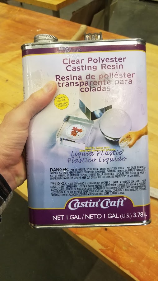
- Clear Polyester Castig Resin
Hilt:
- Transparent PLA
- A 32/8 by 3/4 inch set screw and locker nut
Where did they come from?
- Electronics: all parts came from the shop, with the exception of the LiPO battery and the addressable RGB LEDs. The battery I already had, and the LEDs were bought off Amazon.
- Blade: the foam and silicone mold are from the shop. The crystal resin was lent from Nina (thanks!!!) from the Media Lab has she had spare and it expires anyway.
- Hilt: everything from the shop
How much did they cost?
- Electronics: the main cost is the battery - 6.95$ (on Adafruit). The WS2812b LEDs were 15cent per LED, so 3.15$ total. Attiny84 is 0.75$. the rest is negligible.
- Blade: the foam is scrap, and the resin would have cost me 1$ per ounce (each half blade is around 3 ounces). The 1kg of MoldMax is the main component, with a price of 25$.
- Hilt: at this amount of PLA the cost is negligible
Approximate Total: 43$ (out of which 25$ is the mold, which can be used to make a lot more swords… so the actual cost of parts is around 18$)
What processes were used?
Almost everything! And more importantly, almost every process was new to me before this semester!
- Circuit Board Design and Milling (the sensing+output board)
- Embedded Programming (on device signal processing)
- 3D Modeling (blade+hilt)
- 3D Printing (hilt)
- CNC Milling (blade for molding)
- Molding and Casting (blade)
- Vinyl Cutting (Elvish scripture on the blade + electrodes on the hilt)
How was it evaluated?
My main objective for this project is to showcase a complex piece which I couldn’t have made 3.5 months ago, even if I ad spent 3.5 months self-studying. I believe this goal was achieved. I didn’t expect to fabricate boards from scratch as quickly as I do know, as well as integrating them into real-world objects that are cast from various materials. Cool.
What are the implications?
Sadly, this project doesn’t hold grand implications. It was an integrative masterpiece, where I tried to combine as many new skills I have acquired and having fun along the way. I hope that with the same skills, I can now execute and develop longer term, impactful projects.