Networking and Communications
This week I decided to make something useful. I live in an apartment off-campus, and we have a washing maching that is shared between nine apartments. The washer is at the basement, and I’m on the second floor. Often when I go down to put my laundry, I find the machine is being used. The goal this week is to make a simple communication device that will allow me to know from the comfort of my home, whether the machine is now running or not.
Input
While I did consider putting up a webcam that will stream live. I decided this would be both an overkill and a mild privacy issue. In class we briefly mentioned the piezo sensor that allows to capture vibrations (and more) and we have quite a few lying around at the shop - so I decided to go with that.
First thing, I wanted to see that I can capture a signal - I used one of my previous board. As the piezo just needs one wire to ground and second wire to the microcontroller, I connected it using the ISP header. Using the Attiny ADC I could get a vibration signal and send it to my PC via FTDI. Here’s the code:
#include <avr/io.h>
#include <util/delay.h>

#define output(directions,pin) (directions |= pin) // set port direction for output
#define input(directions,pin) (directions &= (~pin)) // set port direction for input
#define set(port,pin) (port |= pin) // set port pin
#define clear(port,pin) (port &= (~pin)) // clear port pin
#define pin_test(pins,pin) (pins & pin) // test for port pin
#define bit_test(byte,bit) (byte & (1 << bit)) // test for bit set
#define bit_delay_time 102 // bit delay for 9600 with overhead
#define bit_delay() _delay_us(bit_delay_time) // RS232 bit delay
#define half_bit_delay() _delay_us(bit_delay_time/2) // RS232 half bit delay
#define char_delay() _delay_ms(10) // char delay

#define serial_port PORTA
#define serial_direction DDRA
#define serial_pins PINA
#define serial_pin_out (1 << PA2)

#define led_port PORTA
#define led_direction DDRA
#define led (1 << PA3)

void put_char(volatile unsigned char *port, unsigned char pin, char txchar) {
   // Neil's classic put_char method.
}

int main(void) {
   //
   // main
   //
   static unsigned char up_lo,up_hi,down_lo,down_hi;
   //
   // set clock divider to /1
   //
   CLKPR = (1 << CLKPCE);
   CLKPR = (0 << CLKPS3) | (0 << CLKPS2) | (0 << CLKPS1) | (0 << CLKPS0);
   // initialize LEDs
   output(led_direction, led);
   set(led_port, led);
   //
   // initialize output pins
   //
   set(serial_port, serial_pin_out);
   output(serial_direction, serial_pin_out);
   //
   // init A/D
   //
   ADMUX = (1 << REFS1) | (0 << REFS0) // 1.1V ref
         | (0 << MUX5) | (0 << MUX4) | (0 << MUX3) | (0 << MUX2) | (0 << MUX1) | (1 << MUX0); // PA1
   ADCSRA = (1 << ADEN) // enable
      | (1 << ADPS2) | (1 << ADPS1) | (1 << ADPS0); // prescaler /128
   ADCSRB |= (0 << ADLAR);  // right adjust
   //
   // main loop
   //
   while (1) {
      // Sense Vibration
      //
      // send framing
      //
      put_char(&serial_port, serial_pin_out, 1);
      char_delay();
      put_char(&serial_port, serial_pin_out, 2);
      char_delay();
      put_char(&serial_port, serial_pin_out, 3);
      char_delay();
      put_char(&serial_port, serial_pin_out, 4);
      //
      // initiate conversion
      //
      ADCSRA |= (1 << ADSC);
      //
      // wait for completion
      //
      while (ADCSRA & (1 << ADSC))
         ;
      //
      // save result
      //
      up_lo = ADCL;
      up_hi = ADCH;
      //
      // send result
      //
      put_char(&serial_port, serial_pin_out, up_lo);
      char_delay();
      put_char(&serial_port, serial_pin_out, up_hi);
      char_delay();
    }
 }
The main thing to notice is that for Piezo, we ADMUX to use the internal 1.1V reference, instead of the external 3.3V/5V.
Short detour with ESP32-CAM
While I was in the shop figuring out which communication module I better use, a delivery of freshly baked ESP32 came by. I was really impressed by this module (and its price) so I was excited to play around with it. Also, I figured out that to program it for basic stuff (like the web camera server) I don’t even need to mill a new board, I can just plug in an FTDI to USB. One thing to notice that while programming, the GIO0 pin needs to be connected to ground, which can e done by a simple f/f wire.
I tried the FTDI to USB cables lying around the shop, unsuccessfully. I tried running both the Arduino IDE example, as well as the ESP-IDF tutorial. While both tutorials are great, I just couldn’t program/flash the module.
I decided to abandon ESP32 (for now) and use a simpler radio module for my weekly project. A few days later, I used an FTDI programmer to flash ESP32… and it worked like a charm. Lesson: do not use these cables for programming ESP32. Why? my guess is something with power but need to verify.
Radio Boards Design and Production
Pfft a board a week? let’s turn it up to two boards!
I decided to use the nRF24L01+ module for RX/TX radio communication. One board will be connected to a piexo sensor, and transmit the signal. The other board will have an LED and flash it when the received signal passes some hardcoded threshold.
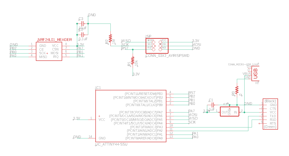
I based my design heavily on Neil’s, just add the needed components. Since using nRF24L01+ takes most of the Attiny44 pins, I decided to re-use the ISP pins for getting input from the piezo sensor and output to the LED.
An important addition to both boards - as I actually want to use this week project and power it, I decided to put in a micro-USB port which will be used only for power supply and ground needs. I will use a 3.3V/5V adapter plugged to the wall, and it should work. Hopefully.
Input/Transmitter Schema:
Board:
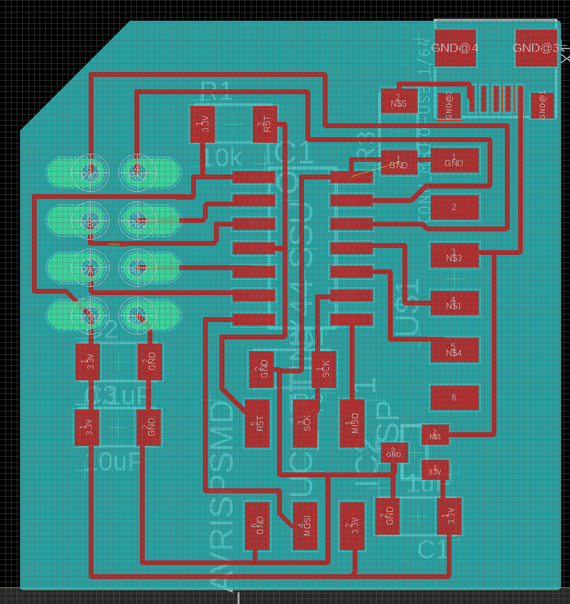
I’m not sure if I broke any design rules, but the milling didn’t go so well and I had quite a lot (~7) mistakes - two adjacent traces that were connected. After a lot of cutting with the razor, and extensive use of the multimeter, the board seemed alright…
 However, there were two major faults in this board… can you spot them?
(Hint, the FTDI header)
The Output/Receiver board is quite similar, with an addition of an LED.
Schema:

Board:
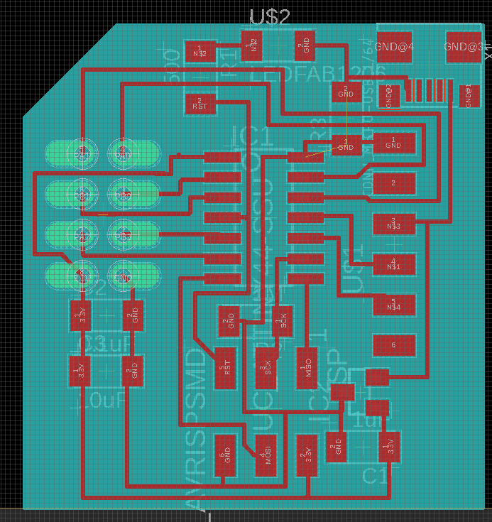
Riddle #2 - this board has a major design flaw, can you spot this one too?
Answer: the LED is connected to the RESET pin! As I learned the hard way, this is the one ISP pin that I cannot re-use, unless I set a fuse in the Attiny which prevents it from ever-being re-programmed again. Not cool, as I plan to experiment with different thresholds.
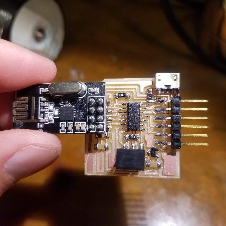
I solved this mess by tearing off the trace that connects the LED with the RST pin, and soldering an overhead wire that connects it with the SCK pin.
 After adding the wire and brutally fixing the FTDI leg. According to the multimeter everything seems alright now.
Embedded Programming
At first glance, the easiest way to communicate using nRF24L01+ is using the comprehensive RF24 Arduino library. I uploaded their example, where the transmitter sends “hello world” every second and the receiver prints this to the Serial output. While I did read some data off the Serial Monitor, it was all jammed up and it seems that something with the Serial connection didn’t work. My suspicion is that perhaps the SoftwareSerial Arduino library doesn’t handle well with the Attiny44 running on the internal clock of 8MHz. I also tried to run my own code where the transmitter sent 0 or 1 every second. And the receiver would blink the LED. However, blinking the LED seemed like a difficult task in Arduino, using digitalWrite. Perhaps because it was connected to the SCK pin.
Long story short, I came back to my beloved C code. Where I could both communicate with my PC clearly at a 9600 baudrate and blink the LED easily. But how do I use nRF24L01+? Luckily, Rob Hart prepared really nice code which uses bit banging and is easy to integrate with the rest of my C code which reads piezo inputs and blinks LEDs.
I will not copy over the whole code (you can see the attached files for that), just the beef: Transmitter:
//
// init A/D
//
ADMUX = (1 << REFS1) | (0 << REFS0) // 1.1V ref
      | (0 << MUX5) | (0 << MUX4) | (0 << MUX3) | (1 << MUX2) | (0 << MUX1) | (0 << MUX0); // PA4
ADCSRA = (1 << ADEN) // enable
   | (1 << ADPS2) | (1 << ADPS1) | (1 << ADPS0); // prescaler /128
ADCSRB |= (0 << ADLAR);  // right adjust

/* init hardware pins */
nrf24_init();

/* Channel #2 , payload length: 4 */
nrf24_config(2,2);

/* Set the device addresses */
nrf24_tx_address(tx_address);
nrf24_rx_address(rx_address);

while(1)
{
  //
  // initiate conversion
  //
  ADCSRA |= (1 << ADSC);
  //
  // wait for completion
  //
  while (ADCSRA & (1 << ADSC))
     ;

  /* Fill the data buffer */
  data_array[0] = ADCL;
  data_array[1] = ADCH;

  /* Automatically goes to TX mode */
  nrf24_send(data_array);

  /* Wait for transmission to end */
  while(nrf24_isSending());

  /* Wait a little ... */
  _delay_ms(10);
}
Receiver:
/* init hardware pins */
nrf24_init();

/* Channel #2 , payload length: 4 */
nrf24_config(2,2);

/* Set the device addresses */
nrf24_tx_address(tx_address);
nrf24_rx_address(rx_address);
//
// main loop
//

while(1)
{
  if(nrf24_dataReady())
  {
      nrf24_getData(data_array);
      //
      // send result
      //
      if (data_array[0] > 10) {
        set(led_port, led);
        _delay_ms(100);
        clear(led_port, led);
      }
  }
}
And the result:
In-The-Wild Testing
Time to actually use this thing! One major concern I had i whether the antenna is trong enough to actually tx/rx from the basement to my apartment. I should note that I do get Wifi signal at my basement so I was hopeful.
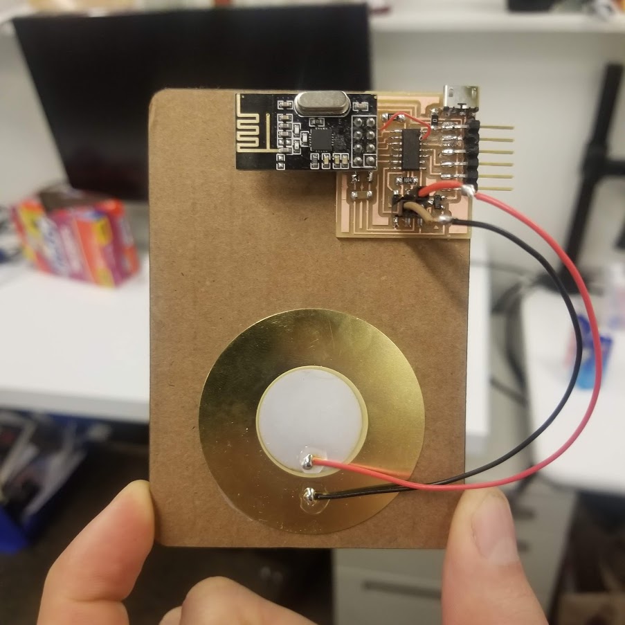
First, I made a nice easy form factor for the transmitter, by laser cutting some cardboard and gluing it all together.
Now, I took the components back home and took my laundry and was all ready for testing. Alas, the simple test I show in the video above didn’t work in my basement. I suspect the receiver device got damaged on the way. The nRF24L01+ module doesn’t “sit” tight (which seems bad) and worst of all, when I jiggle it a bit the LED randomly lights up (even when the transmitter is off). I don’t have a multimeter at home so I wasn’t able to test what went wrong. I think I might just mill a new board in December, or maybe use the now-working ESP32 connected to a piezo to stream live the washer vibrations?

The Eagle design files and Arduino+C code are all here ADD LINK