Input Devices
This week my plan was to learn and make an device based on electrodermal activity input. Also known as Glavanic Skin Response, the basic concept is that the electric properties of the human skin change as a measure of emotional responses. A common phenomenon is a quick rise in EDA as a response to a scary scenario. Thus, the goal this week is to create a board, which will measure EDA and prove so by watching scary video clips and see the measurement rises.
Electronic Design (Schema)
To understand how will the circuit look like, I consulted with Abhi Jain from FLuid Interfaces. It turns out the circuit to capture the analog signal of EDA is super simple:
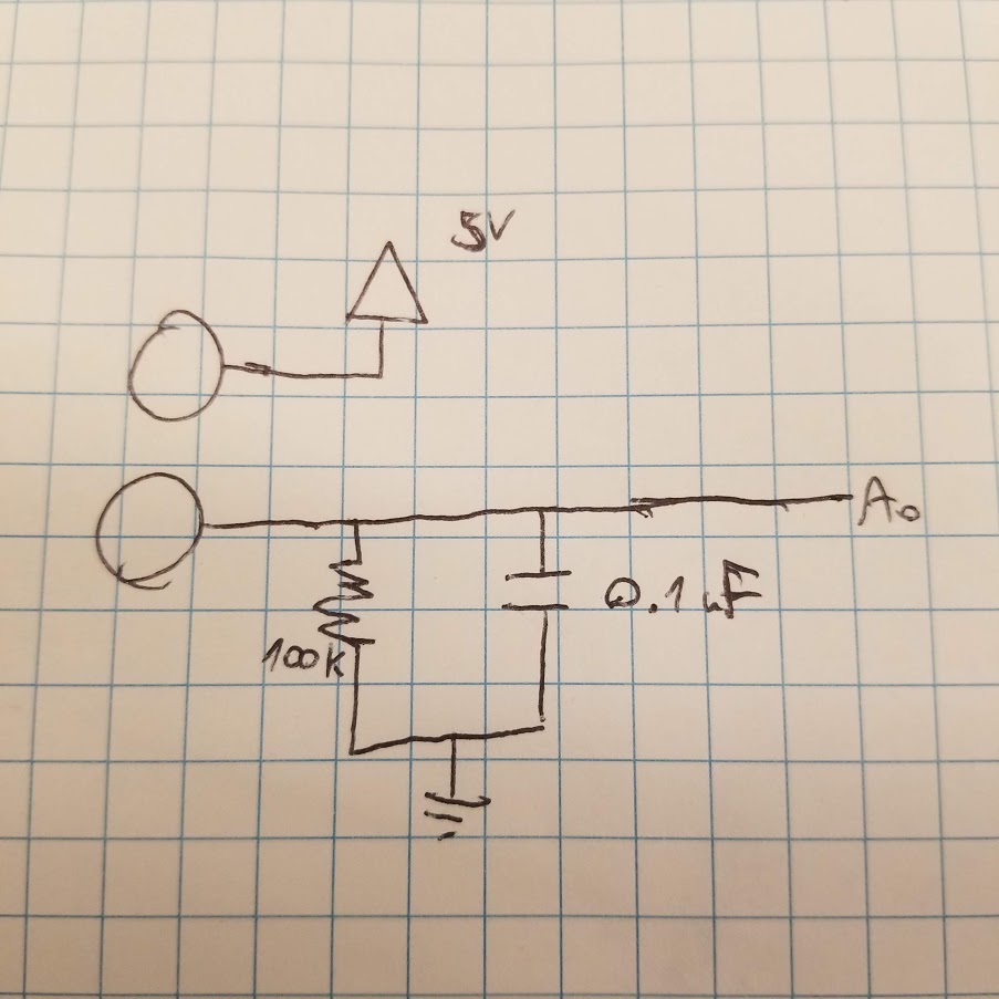
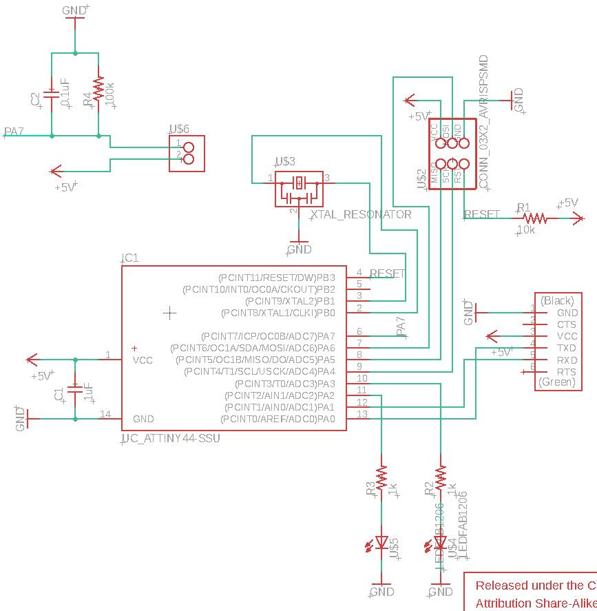
Thus, I used Eagle based on the same schema I had for week 7 using the Attiny44, just replacing the botton with another LED (I wanted one LED to be always on, and to have another LED that I can play around with) and adding the EDA circuit. I added the output of the circuit to a fee pin, PB2 - which turned out be to be big mistake. As I need the ADC component of the microcontroller to convert the analog signal to digital, I didn’t notice the ADC only accepts inputs on port A (oh datasheet, you so smart). Later on how I solved this, but here is the updated schema with the EDA circuit on A7:
Electronic Design (Board)
One special thing about board design, how would to electrodes (wires attached to copper sheets) would be connected to the board. While I could just solder the wire straight to a trace, I thought it could be useful to have “plug and play” feature like the FTDI header. While the FTDI header in the shop can be split to as many legs as you wish, the Eagle inventory only had a footprint for the 6x FTDI header. So I ended up making a new part, which literally took last time than writing this last paragrapj. I copied the schema design for another 2x connection part in the library, and the footprint I copied over from the 6x FTDI header and deleted 4 pads. A new part is now part of this world:

And except that, design the board was pretty straightforward. Notice that for future reference I’m posting the correct design where the EDA circuit is routed to A7 rather than B2.

Milling + Soldering
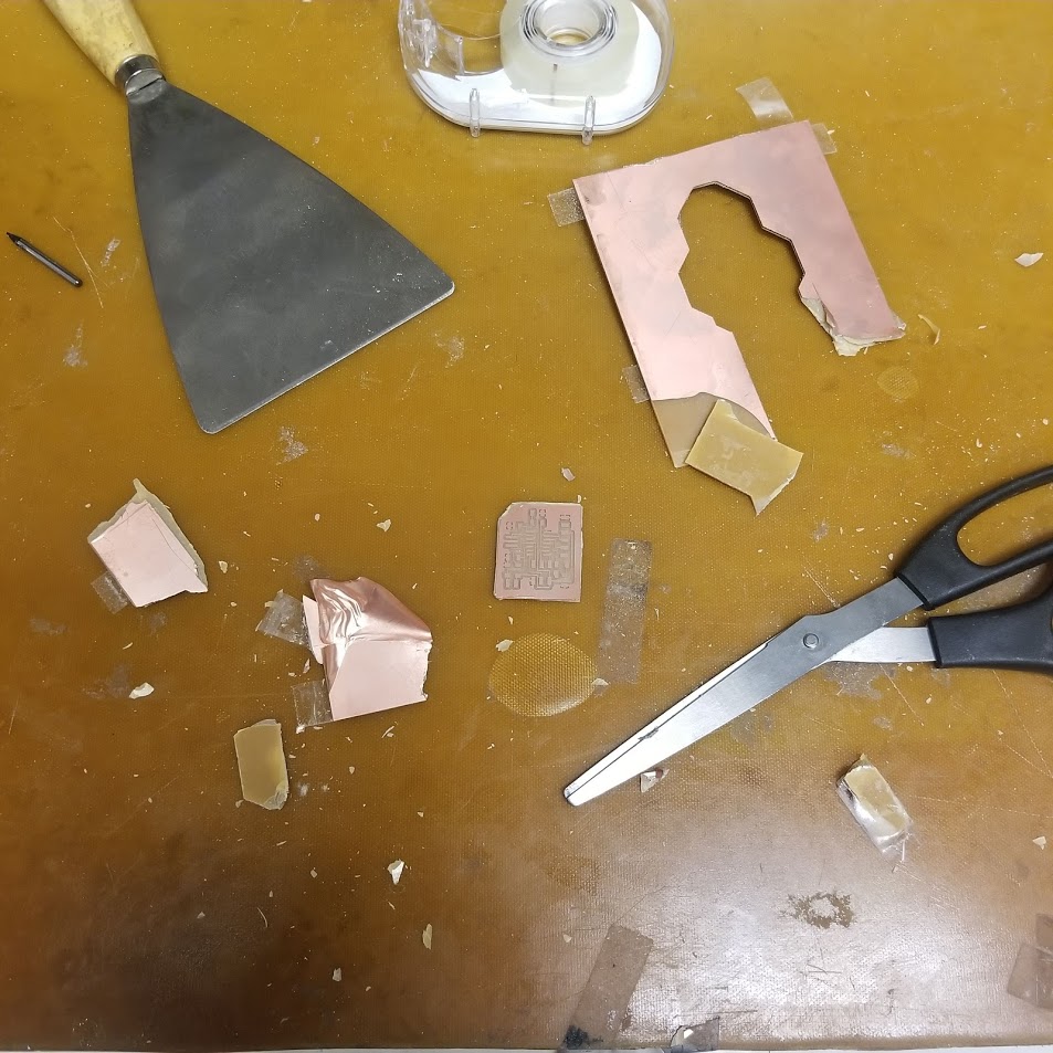
My first milling+soldering attempt was unsuccessful. I milled the traces using a 1/64 endmill, but then couldn’t find a 1/32 endmill around. It was late at night so I decided to hack it - and I cut out the board using a good old pair of scissors:
On to soldering, my bad luck continued (or maybe it was the board that was no longer straight and copper-tight) - and I did a mess out of soldering. I tried to fix it as well as I could, but eventually I decided to give it a go and program it to echo hello-world. While the fuses command worked perfectly, after that I got the dreaded rc=-1. I noticed that my resonator is soldered badly, and after numerous attempt of using the heat gun and re-soldering, as well as replacing the whole Attiny44 with a new one - I couldn’t get past rc=-1. Eventually I decided to mill a new board, and took extra caution to solder it right - programming it with no troubles at all!
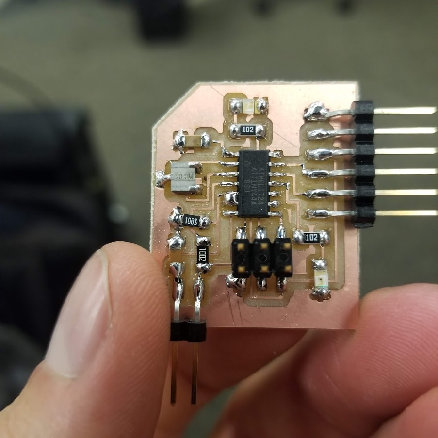
Here are the two boards, one good and one bad (and ugly). Can you guess which is which?

As I’ve mentioned. I made a mess out of my pins by connecting EDA to PB2. Luckily, one pin physically next to PB2 is PA7 and it was free to use! Consulting with Jiri, I decided to solder them together, and on the embedded software side make sure that PB2 is set to input. Here is the final board:
Programming
After a few tests to make sure I can make the LED blink. I based my code out of Neil’s example of using step response to detect loads. My case was different though - since I’m using Attiny44 and not 45, the configuration of the ADC is a bit different (datasheet hurray). Also, for EDA I don’t need a charge and discharge, so it’s a simpler case. Again, notice that I am setting PB2 as input just to clean up my design mess. Below is the code, without put_char(...) as it’s long and exactly the same as the one in hello.load.45.c:
#include <avr/io.h>
#include <util/delay.h>

#define output(directions,pin) (directions |= pin) // set port direction for output
#define input(directions,pin) (directions &= (~pin)) // set port direction for input
#define set(port,pin) (port |= pin) // set port pin
#define clear(port,pin) (port &= (~pin)) // clear port pin
#define pin_test(pins,pin) (pins & pin) // test for port pin
#define bit_test(byte,bit) (byte & (1 << bit)) // test for bit set
#define bit_delay_time 8.5 // bit delay for 115200 with overhead
#define bit_delay() _delay_us(bit_delay_time) // RS232 bit delay
#define half_bit_delay() _delay_us(bit_delay_time/2) // RS232 half bit delay
#define char_delay() _delay_ms(10) // char delay

#define serial_port PORTA
#define serial_direction DDRA
#define serial_pins PINA
#define serial_pin_out (1 << PA1)

#define leds_port PORTA
#define leds_direction DDRA
#define led_1 (1 << PA3)
#define led_2 (1 << PA2)

#define mess_port PORTB
#define mess_direction DDRB
#define mess (1 << PB2)

void put_char(volatile unsigned char *port, unsigned char pin, char txchar) {
   // See http://academy.cba.mit.edu/classes/input_devices/step/hello.load.45.c
}

int main(void) {
   //
   // main
   //
   static unsigned char up_lo,up_hi;
   //
   // set clock divider to /1
   //
   CLKPR = (1 << CLKPCE);
   CLKPR = (0 << CLKPS3) | (0 << CLKPS2) | (0 << CLKPS1) | (0 << CLKPS0);
   // initialize LEDs
   output(leds_direction, led_1);
   output(leds_direction, led_2);
   set(leds_port, led_1);
   clear(leds_port, led_2);
   // I did a mess in the design, so I have to make sure PB2 is input
   input(mess_direction, mess);
   //
   // initialize output pins
   //
   set(serial_port, serial_pin_out);
   output(serial_direction, serial_pin_out);
   //
   // init A/D
   //
   ADMUX = (0 << REFS1) | (0 << REFS0) // Vcc ref
      | (0 << MUX5) | (0 << MUX4) | (0 << MUX3) | (1 << MUX2) | (1 << MUX1) | (1 << MUX0); // PA7
   ADCSRA = (1 << ADEN) // enable
      | (1 << ADPS2) | (1 << ADPS1) | (1 << ADPS0); // prescaler /128
   ADCSRB |= (0 << ADLAR);  // right adjust
   //
   // main loop
   //
   while (1) {
      //
      // send framing
      //
      put_char(&serial_port, serial_pin_out, 1);
      char_delay();
      put_char(&serial_port, serial_pin_out, 2);
      char_delay();
      put_char(&serial_port, serial_pin_out, 3);
      char_delay();
      put_char(&serial_port, serial_pin_out, 4);
      //
      // initiate conversion
      //
      ADCSRA |= (1 << ADSC);
      //
      // wait for completion
      //
      while (ADCSRA & (1 << ADSC))
         ;
      //
      // save result
      //
      up_lo = ADCL;
      up_hi = ADCH;
      //
      // send result
      //
      put_char(&serial_port, serial_pin_out, up_lo);
      char_delay();
      put_char(&serial_port, serial_pin_out, up_hi);
      char_delay();
    }
 }
Testing (with the oscilloscope)
For my final project, I was hoping to put an EDA sensor on the handle of a sword, and make it glow as a response to strong differences. So to simulate that, I pasted two copper sheets on a cardboard tube and soldered the to wires with female heads. I also create two more pairs of electrodes using copper sheet, so I can simulate and understand the differences of the size of the electrode.
I tried to connect the oscilloscope to the PA7 pin while I was pressing the electrodes. However, I couldn’t get a stable signal. I did see some small perturbations as a response to my pressing and unpressing, but it was not clear enough if this is actually working, let alone if this is EDA.
Testing (with software)
I opted to go and read the signal on the laptop and see if it makes sense. To read and display the signal on my laptop, I used a modified version of Neil’s code - hello.load.45.py. I plugged it all in, and amazingly - it worked! I was getting some kind of signal as a response to me touching and pressing it.
To test my actual EDA response, I watched a jump scare video on my laptop while watching the signal values in realtime, here is my first attempt:
There is a significant increase… Cool! but, I did notice that the signal is very sensitive to pressure, and I wasn’t sure if what I’m seeing here is actual EDA or just me pressing the tube harder because that video was pretty scary. So I performed another test, this time I taped two electrodes to my wrist, so pressure should no longer be an issue. And here is the result:
It works! quite a significant rise in EDA right after the scary moment. One thing to notice that this was the second time I watched this video, so I think the slight EDA increase before the scare might be related to me anticipating it. Nonetheless, I think it’s good enough for now.
Open question
It seems I won’t be able to use electrodes on the handle itself, as it’s too sensitive to pressure - or is it? can I connect a third electrode that will mease load, and use it to normalize the EDA signal?
All of the original files (Eagle design files, C code+Makefile, Python interface) are available here.