(Click here to go down to the brainstorming and weekly progress!)
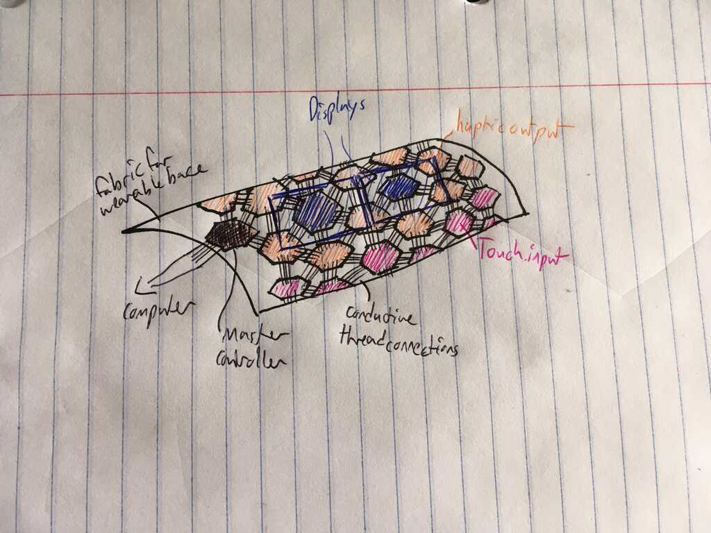
Well, you've followed me this far, so now you get to see where all of this led to!
Circuit Design
The most complicated part of this process by far was designing the circuits. Fortunately, every week got me closer to the final design. So many boards.
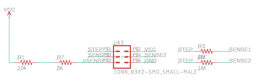
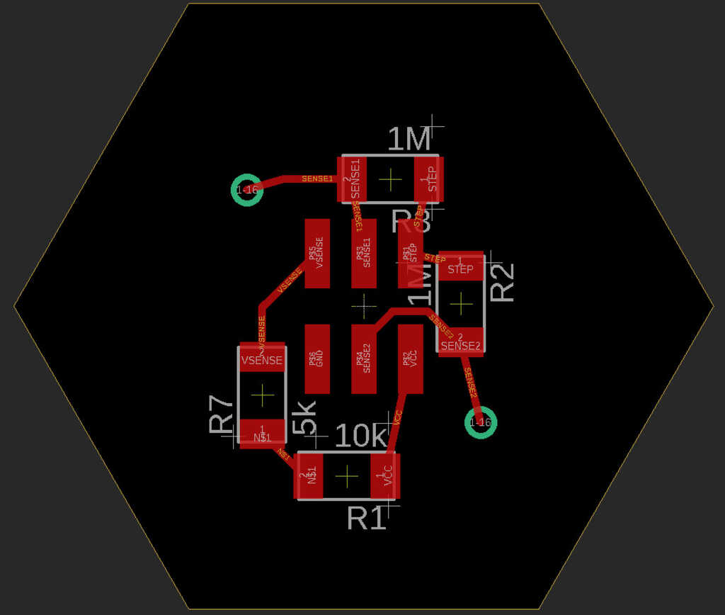
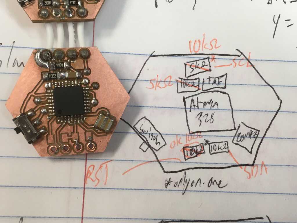
So the first thing to tackle in the design was how to determine which peripheral is currently plugged into the module. I tackled this using a voltage divider, where the ground side is on the module, and the vcc side is on the peripheral.
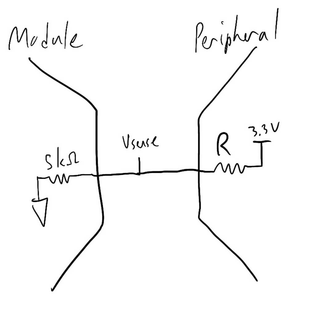
This is a chart showing the different resistances I chose. They were selected based on what we had in the inventory (I later found out that the EDS has a book full of thousands of resistors that I could have used), and what would give me a large difference between perceived Vsense values.

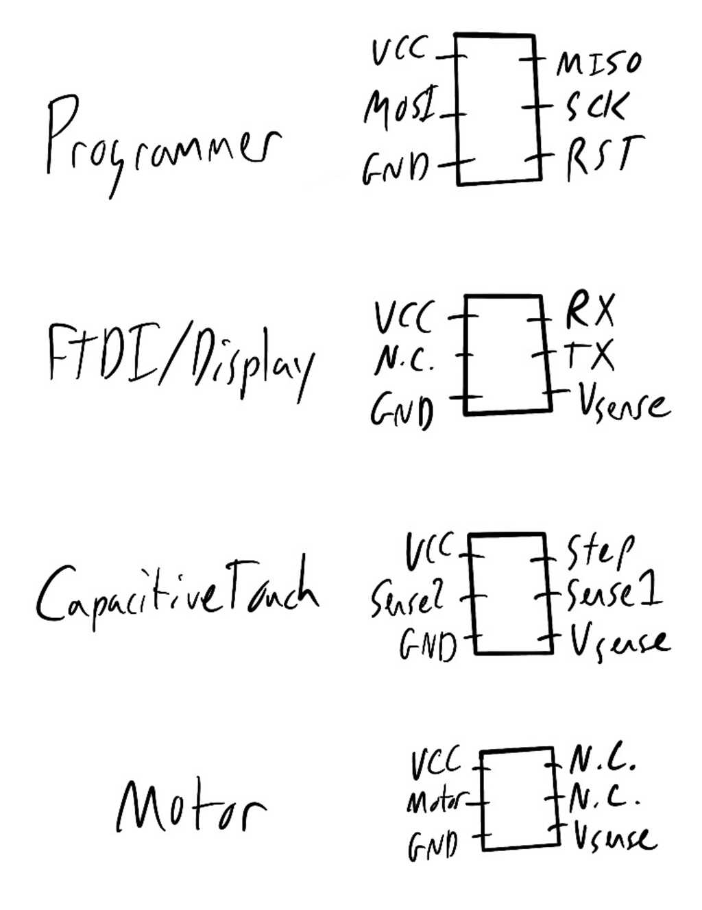
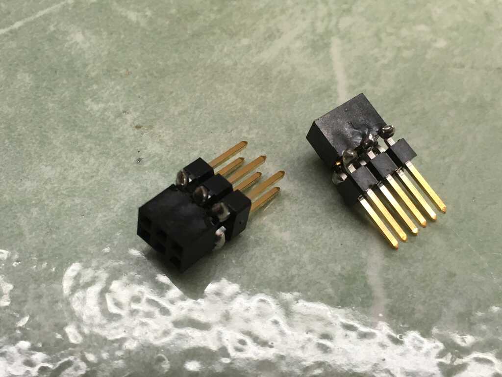
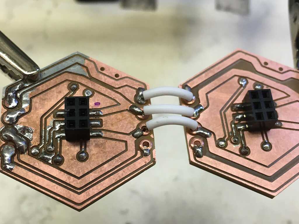
Another issue to address was how to connect the modules to the peripherals. I obviously wanted to be able to program the modules, which required 6 pins for ISP. The reset pin, however, means that one of the pins is entirely useless for the rest of the peripherals. To get around this, I added a switch to swap between the reset pin and an analog input pin. Nice, now I don't have to account for the programmer on deciding the number of necessary pins! The prototype in Week 13 used some janky normal sized headers, so I got these male and female headers from DigiKey. They're smaller and shorter, and are actually in a 2x3 package, meaning my pinouts can ultimately end up looking like this:
Those headers didn't have footprints in Eagle, so I had to make my own. Now let's get into the circuits!
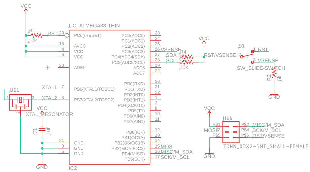
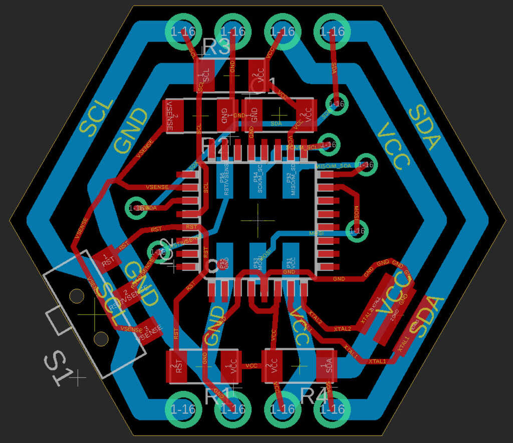
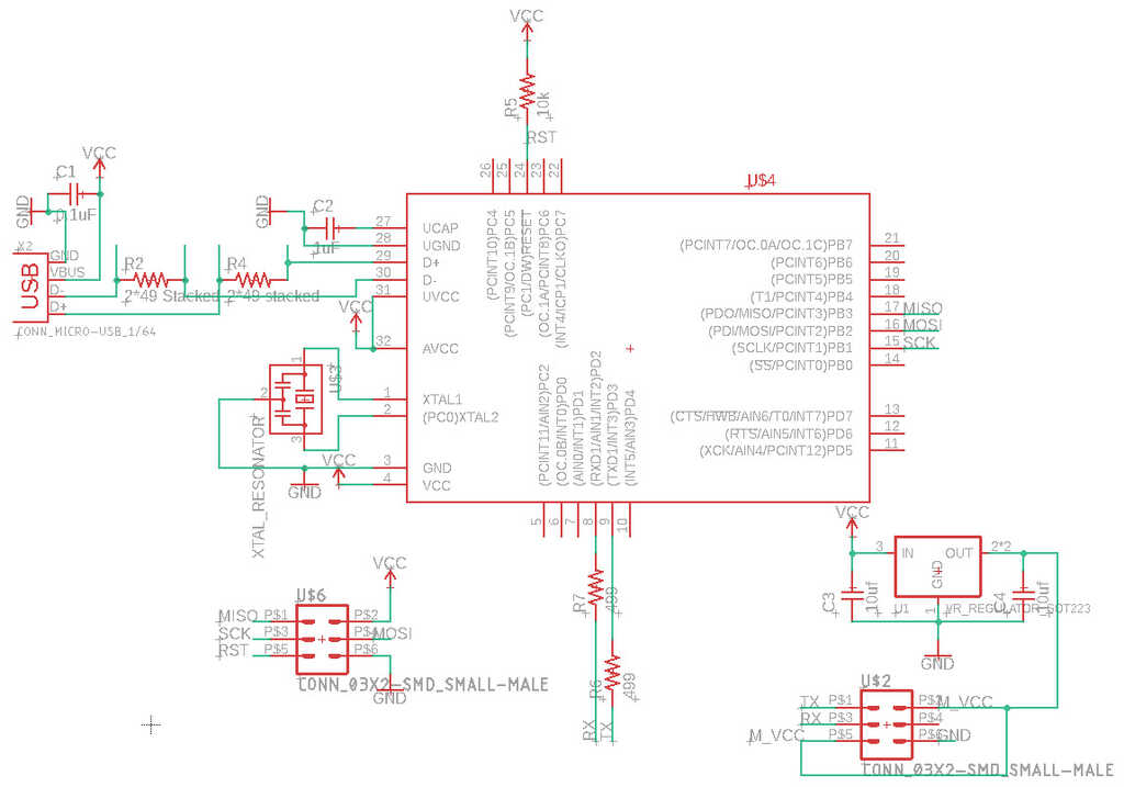
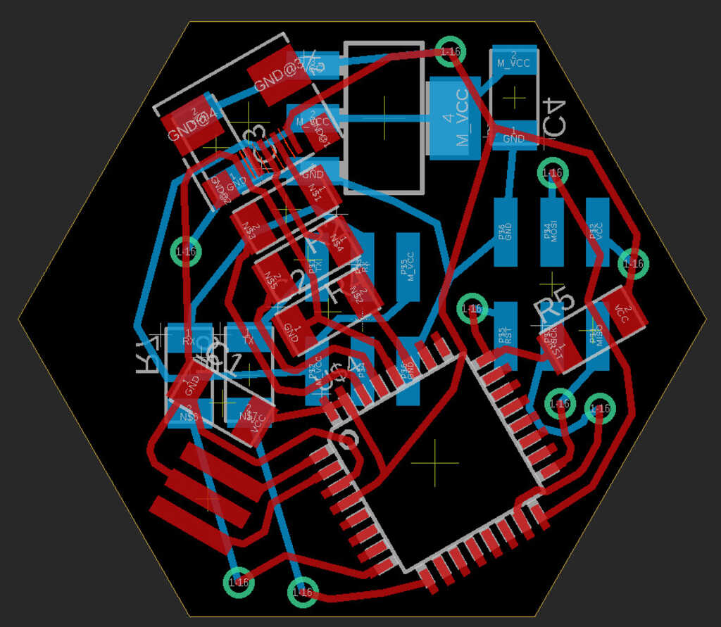
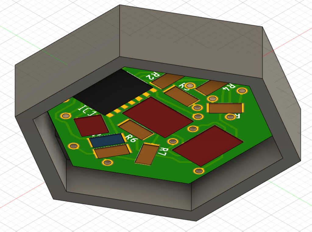
The Module
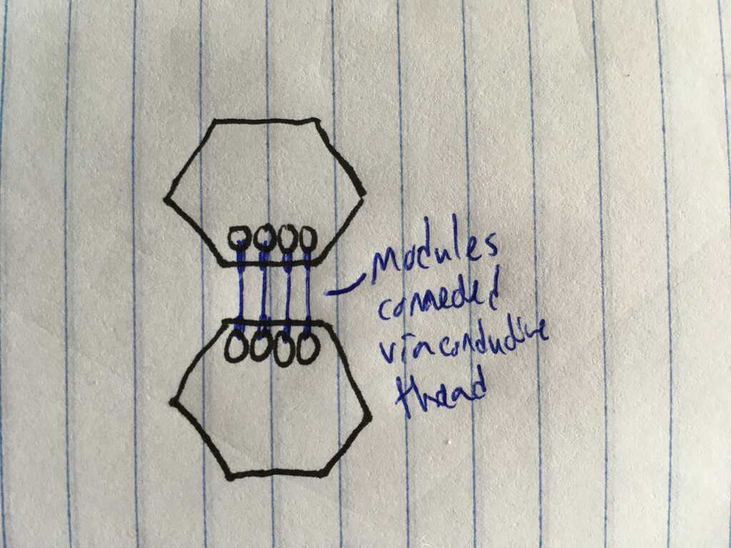
Knowing that connections in all directions didn't work out so well in Week 11, I simplified the design to be 1 dimensional. Since I'll be using I2C, this doesn't affect the functionality, just the form. The most important part here is the microcontroller. I decided on the ATmega328p this time around since it's in the inventory and has an I2C bus. According to the data sheet, running at 3.3v it can go up to ~8MHz, so I added an 8MHz resonator to help it keep better time. The resistors attached to SDA and SCL only need to be put onto one of the actual boards; the rest don't need them. Doing it like this allows me to use one schematic for all of the modules.
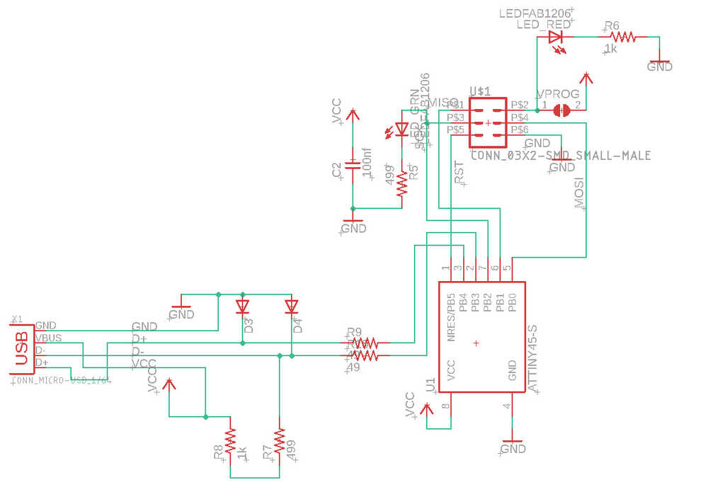
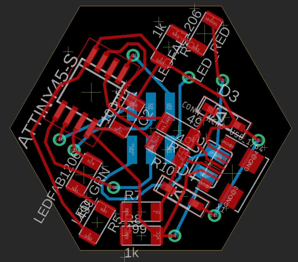
The Programmer
Sticking with a tried and true design, I recreated the same programmer from before using the new headers.
FTDI
Another important component is the FTDI board. Without it, we can't talk to the computer, and we can't get power. It's virtually identical to the one in Week 11, but rotated slightly and with the new header added on. It needs a programming header, so I moved it to the bottom so it wouldn't stick out.
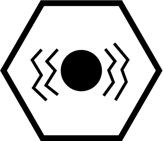
Capacitive Touch
After all of the suffering in Week 9, I decided to go with a more simplified version of the capacitive touch sensor. One change is only two inputs, which allows for larger touch pads, and a simpler design. I also placed the vias in such a way that allows for the two touch pads to be placed vertically, horizontally, or diagonally, which you'll see later. Additionally, reducing the inputs means that I can interface this directly with the module's microcontroller.
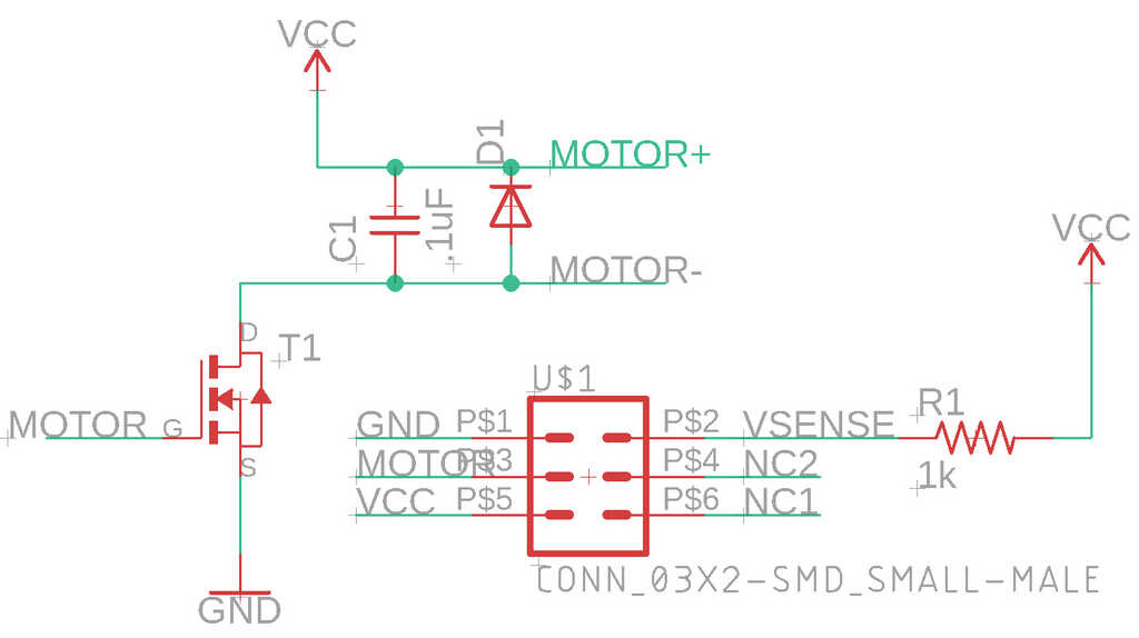
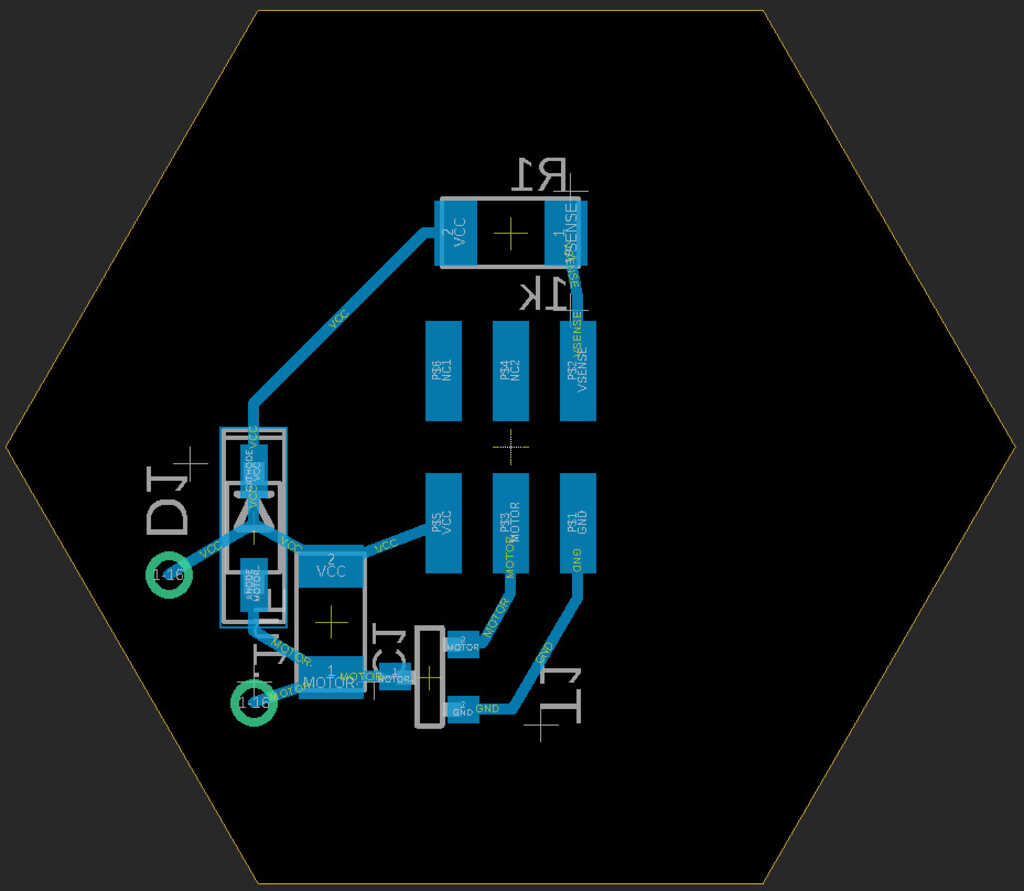
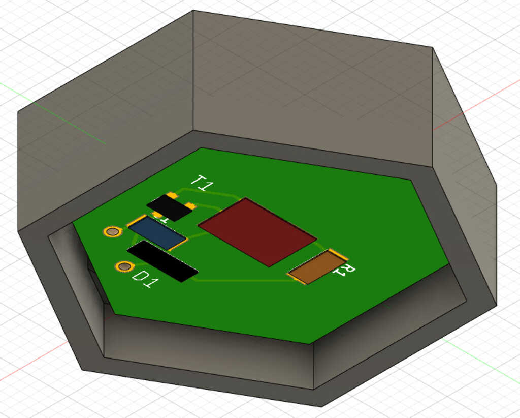
Motor
Similarly, I opted for a simple design with the motor peripheral. The pin to control the motor goes directly from the module to an n-mosfet.
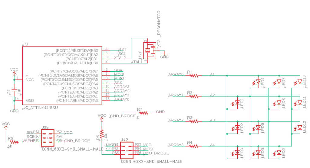
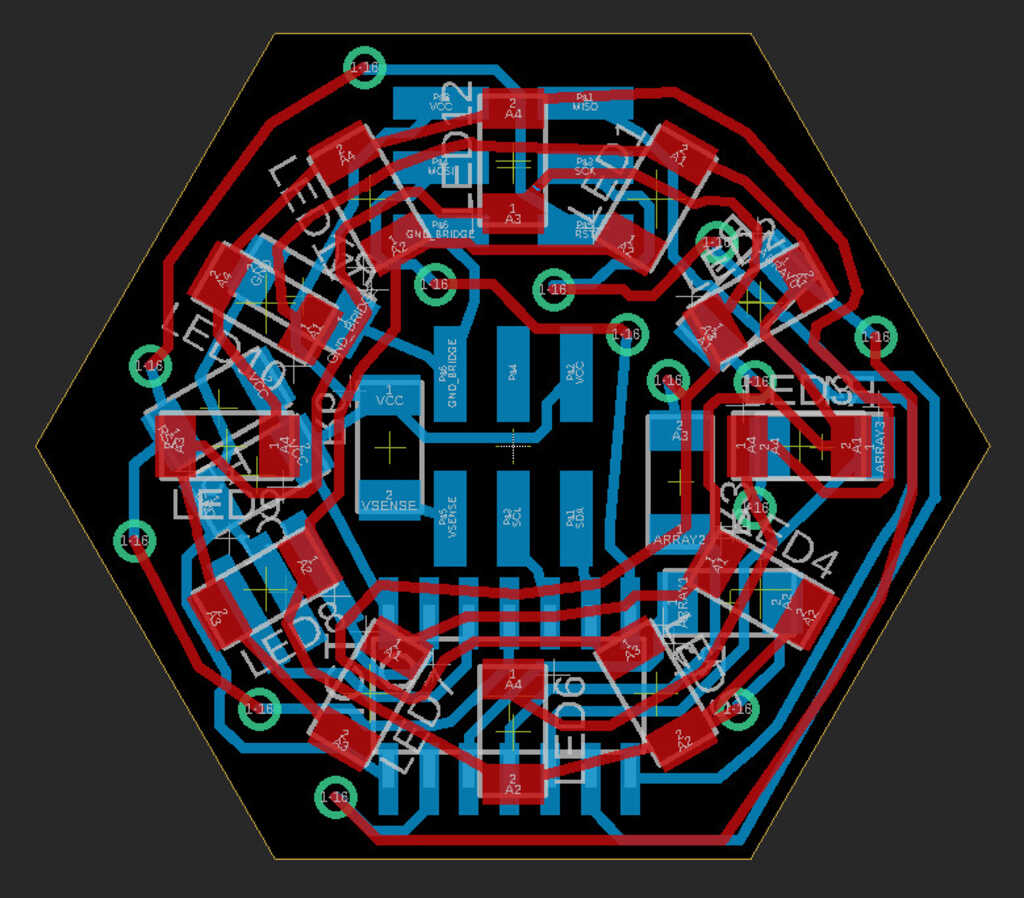
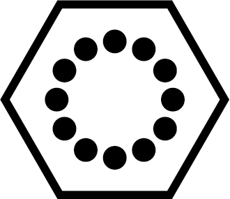
Display
Still iterating off of Week 10 and Week 11, the ring display shares a lot in common with its ancestors. Since the smaller headers only have enough space for one trace underneath and none between the feet, I had to basically reroute the bottom from scratch.
Whew, that's a lot of planning, now let's get to making
Circuit Fabrication
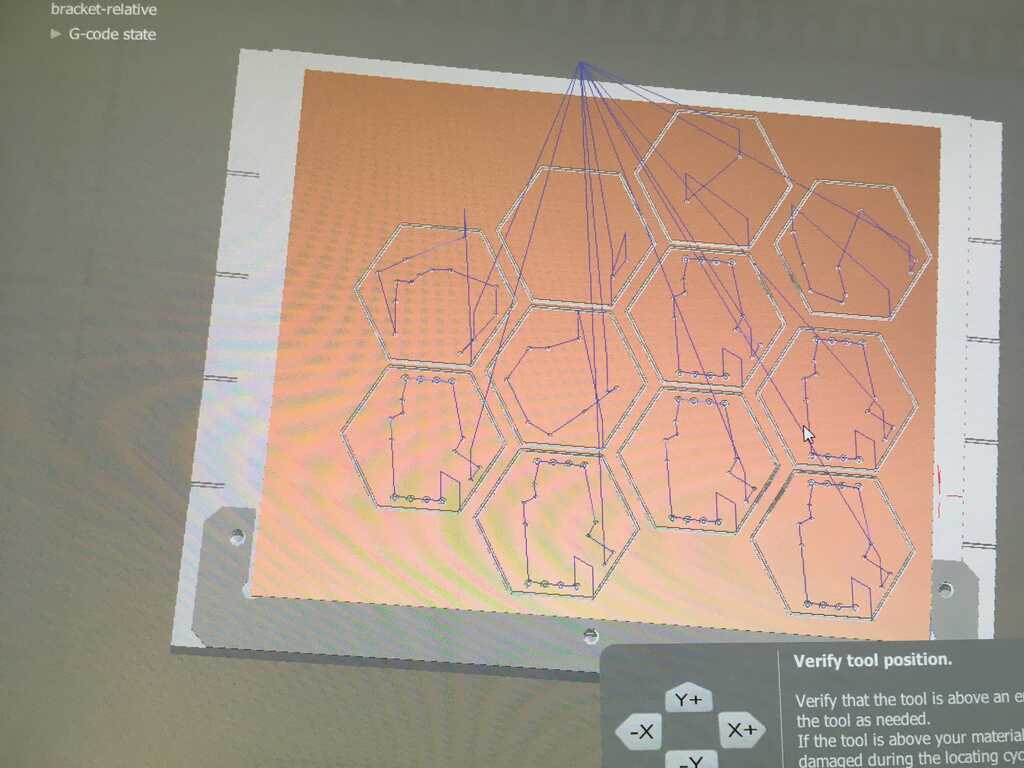
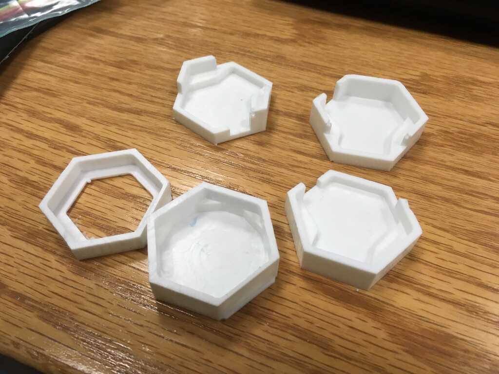
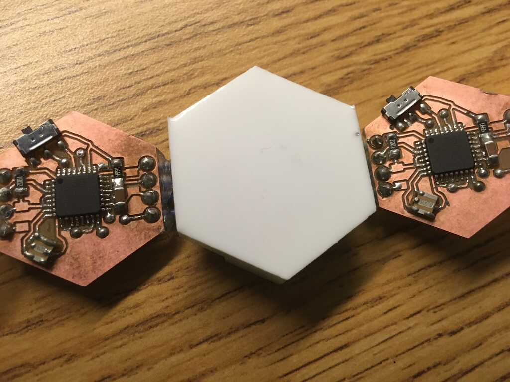
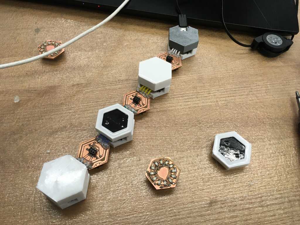
To test all of these circuits, I decided I need one of each peripheral, and at least 2 modules (one hooked up to FTDI, and the other hooked into a module). I used the Othermill, once again. To maximize the space on the boards, I had to be careful with how I patterned them.
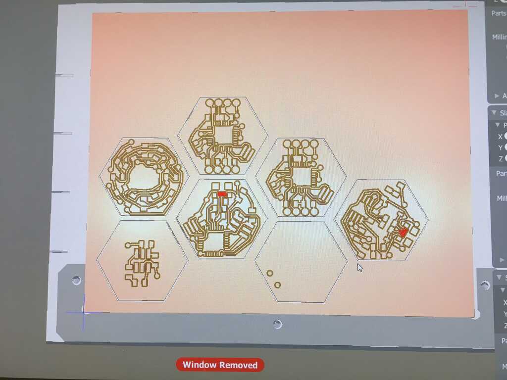
The process I found that worked most efficiently was to mill all of the traces with a 1/64 end mill on one side, flip the board, run the traces again in the same way. Then, cut the holes and outline with a 1/32 end mill, one board at a time. The end mill tends to get gunked up with the tape at the bottom, which can lead to it tearing traces out as it does the holes, so cleaning it up between boards was very useful.
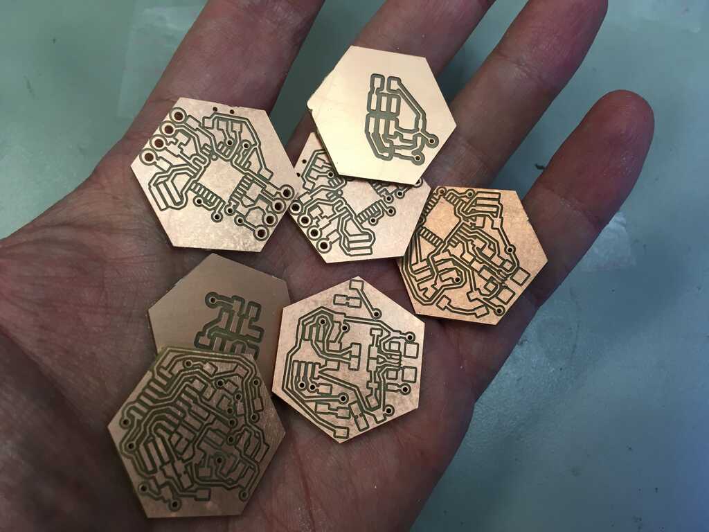
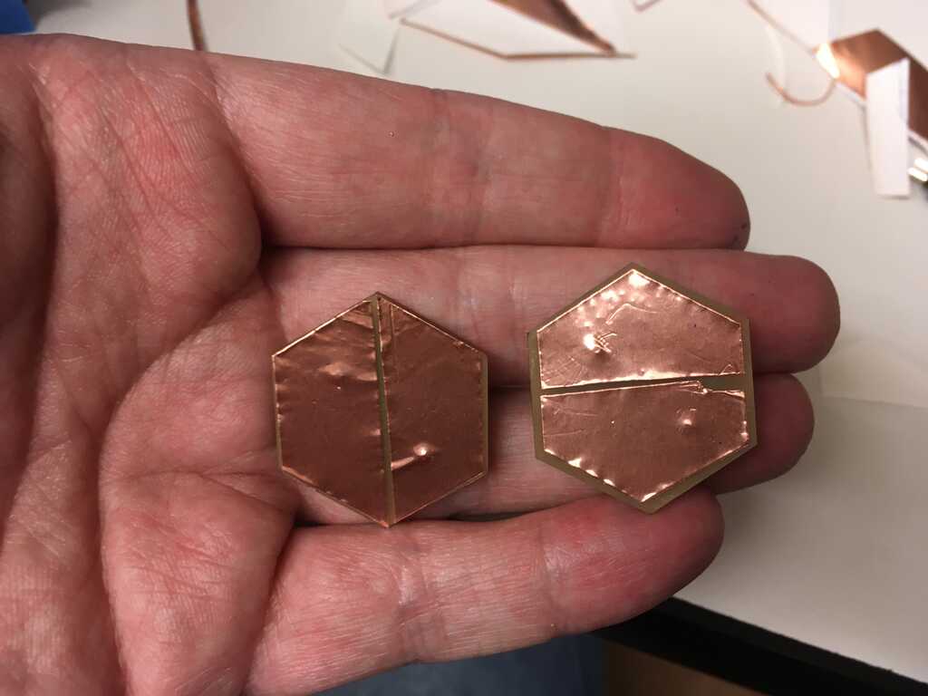
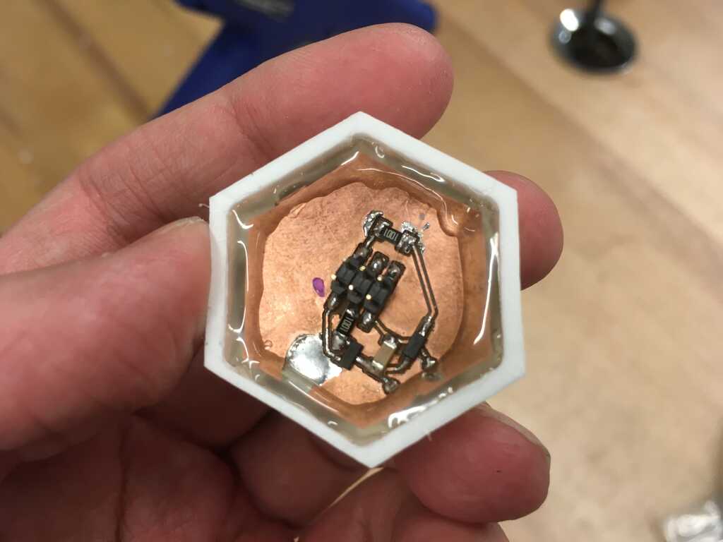
The boards kinda feel like coins, they're so fun to hold and look at.
To program the display, FTDI, and programming boards, I needed an adapter. So, I soldered the feet of a couple small female headers to the feet of normal-sized male headers, and made my adapters! Kinda sketchy, but hey, it works.
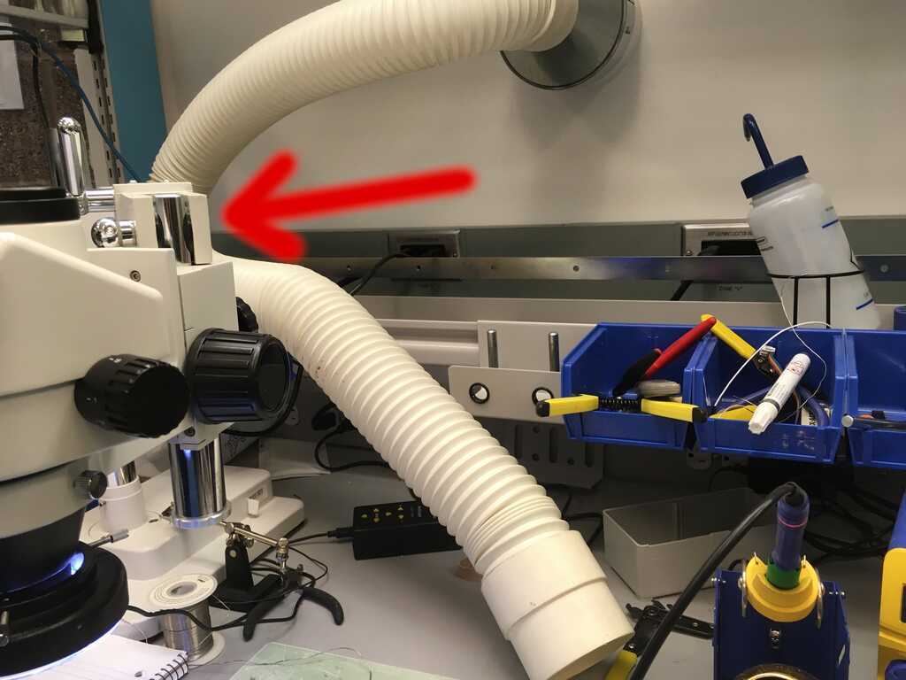
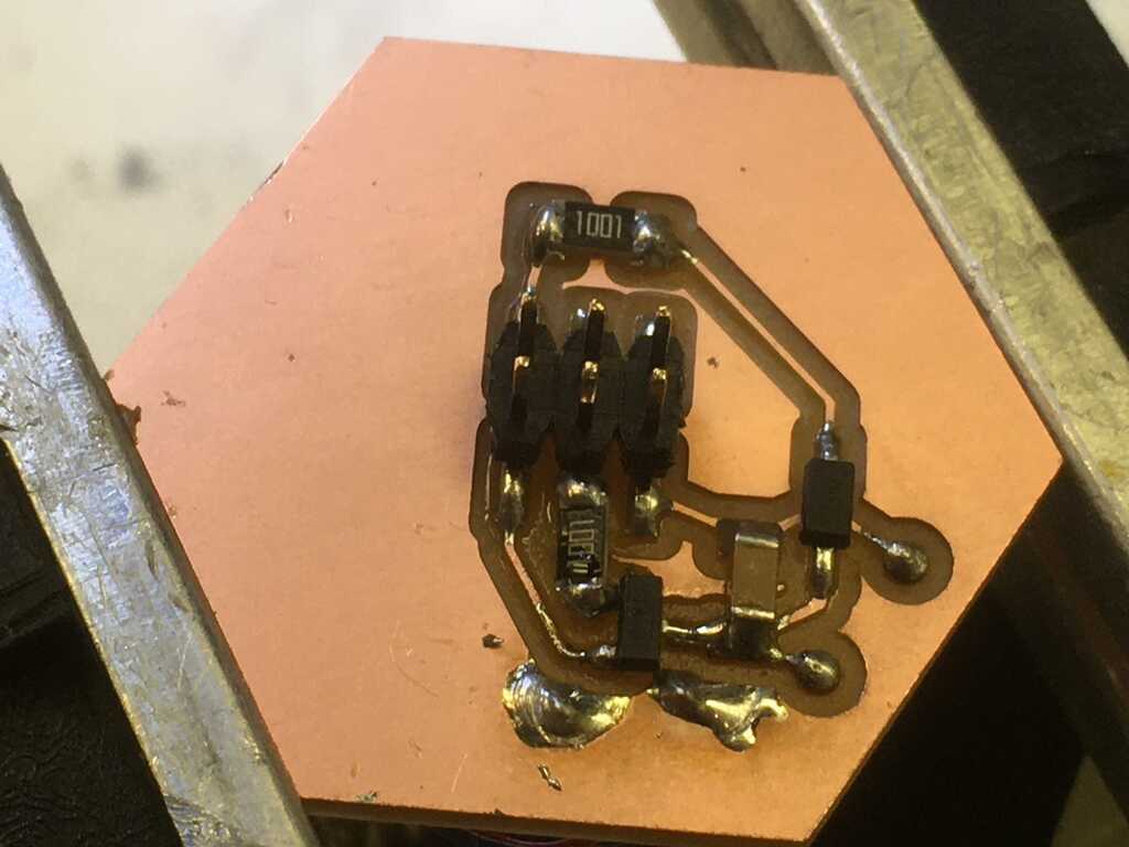
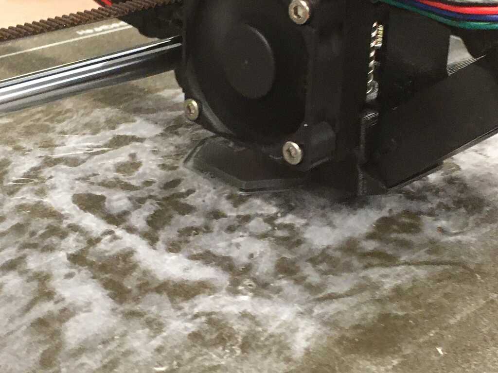
The next step was to stuff the boards, which is fairly straightforward. I did run into a bit of an issue, though. We have these white pipes in the EDS that ventilate, and it's nice for soldering. Recently, the suction of the two pipes got balanced out. I still wasn't used to this, and had it a little too close to my workspace. All of a sudden, I heard something get sucked up the pipe. At the same time, believe it or not, one of my circuits went missing. Luckily, the circuit got stuck where the pipe bends, and I was able to pull the hose off the wall and get my circuit out. Phew!
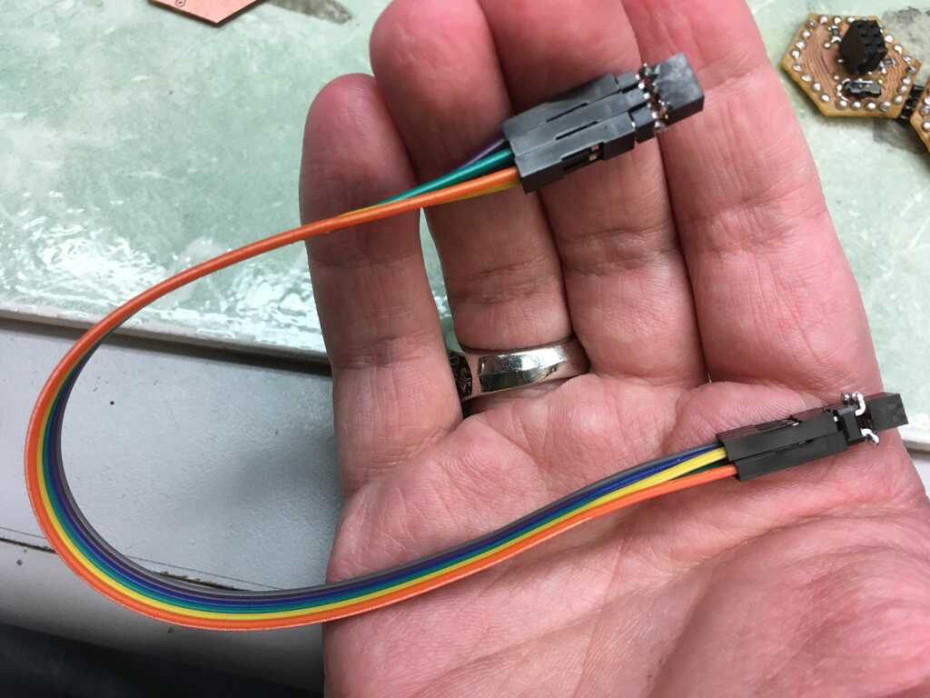
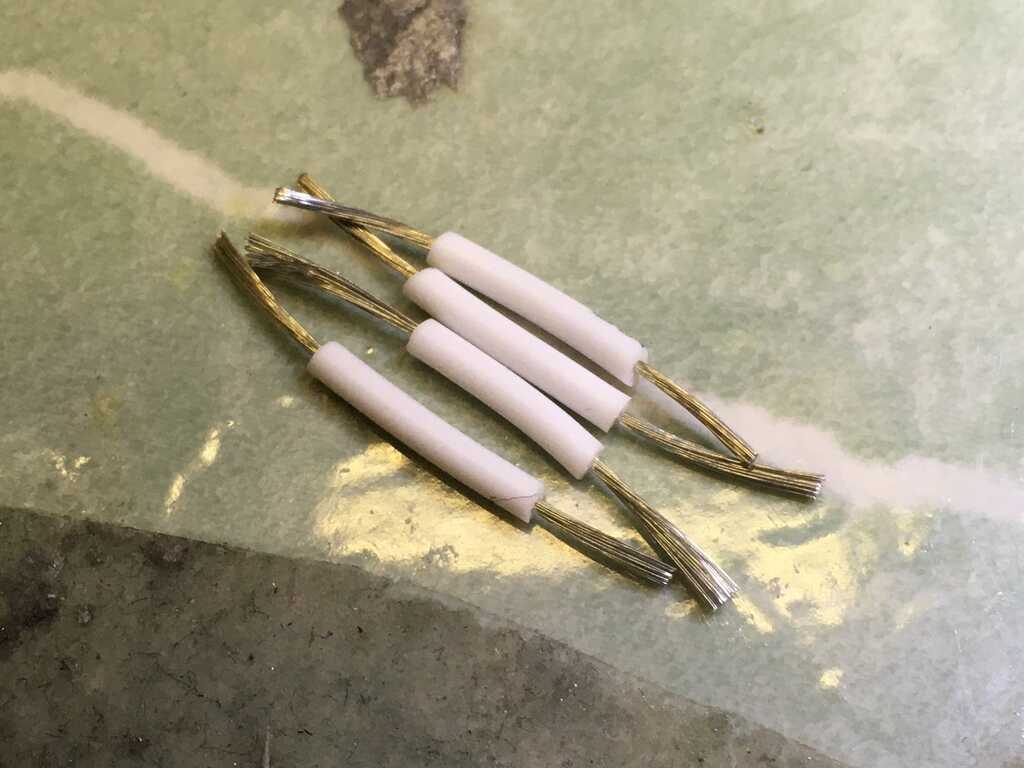
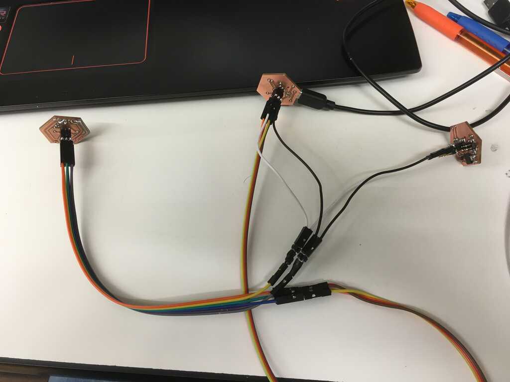
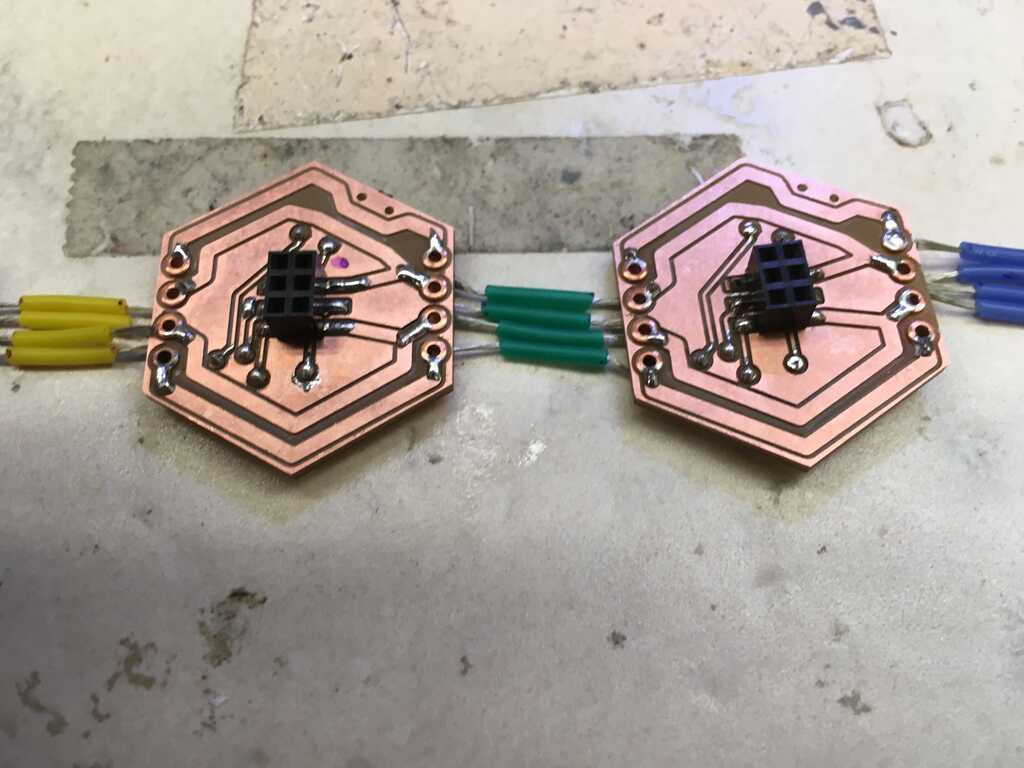
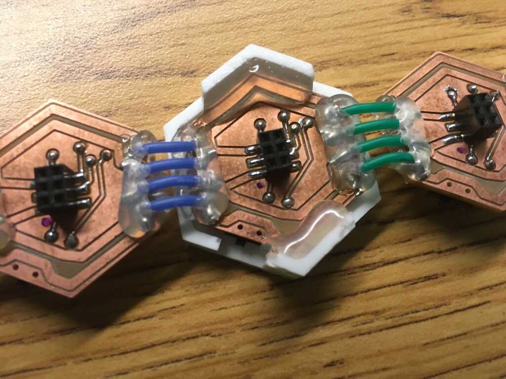
To combine the circuits, the wire I used in Week 11 was much to stiff. So instead, I used some stranded wire I've had laying around for years. It flexed way better.
After some circuit debugging I realized I mixed up some of the resistor locations. It led to some very bizarre and buggy behavior.
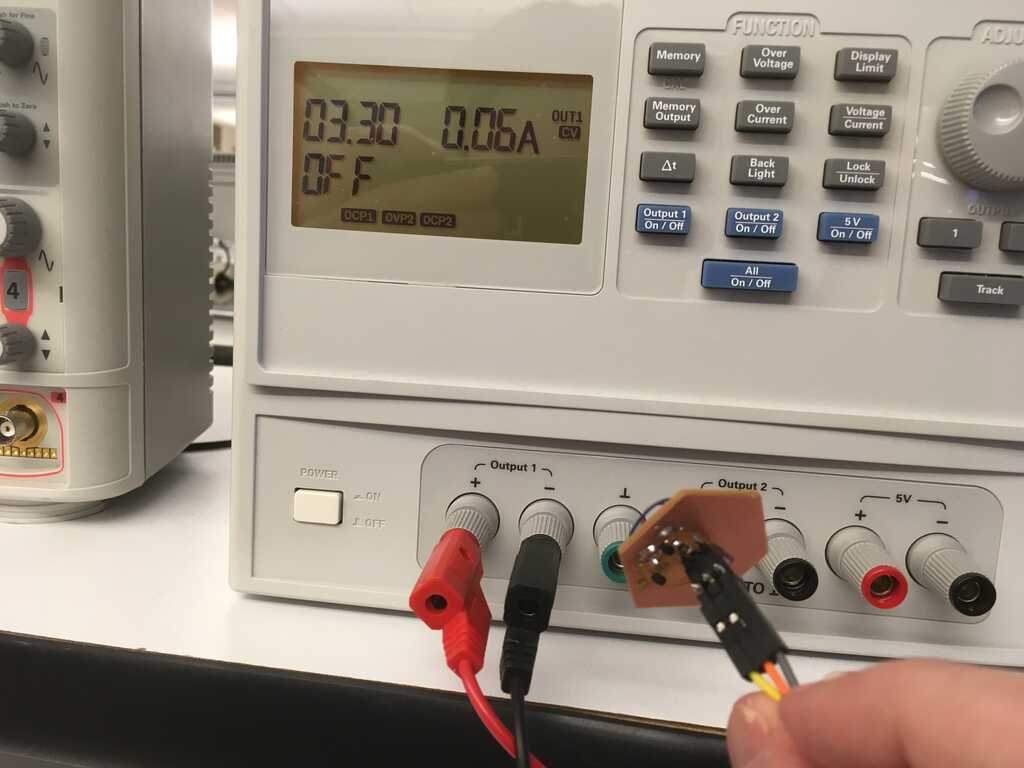
Other debugging included testing the motor circuit. When I hooked it up to a power supply (maxed at 1 amp), it drew the entire amp. I was really concerned, but apparently the gate on the mosfet was drawing all of that current? Fortunately all that meant was a fried mosfet, so I jankily soldered a 1kΩ resistor between the pin and the gate on a new mosfet and that got the job done. Now only drawing 60mAmps when the motor is running!
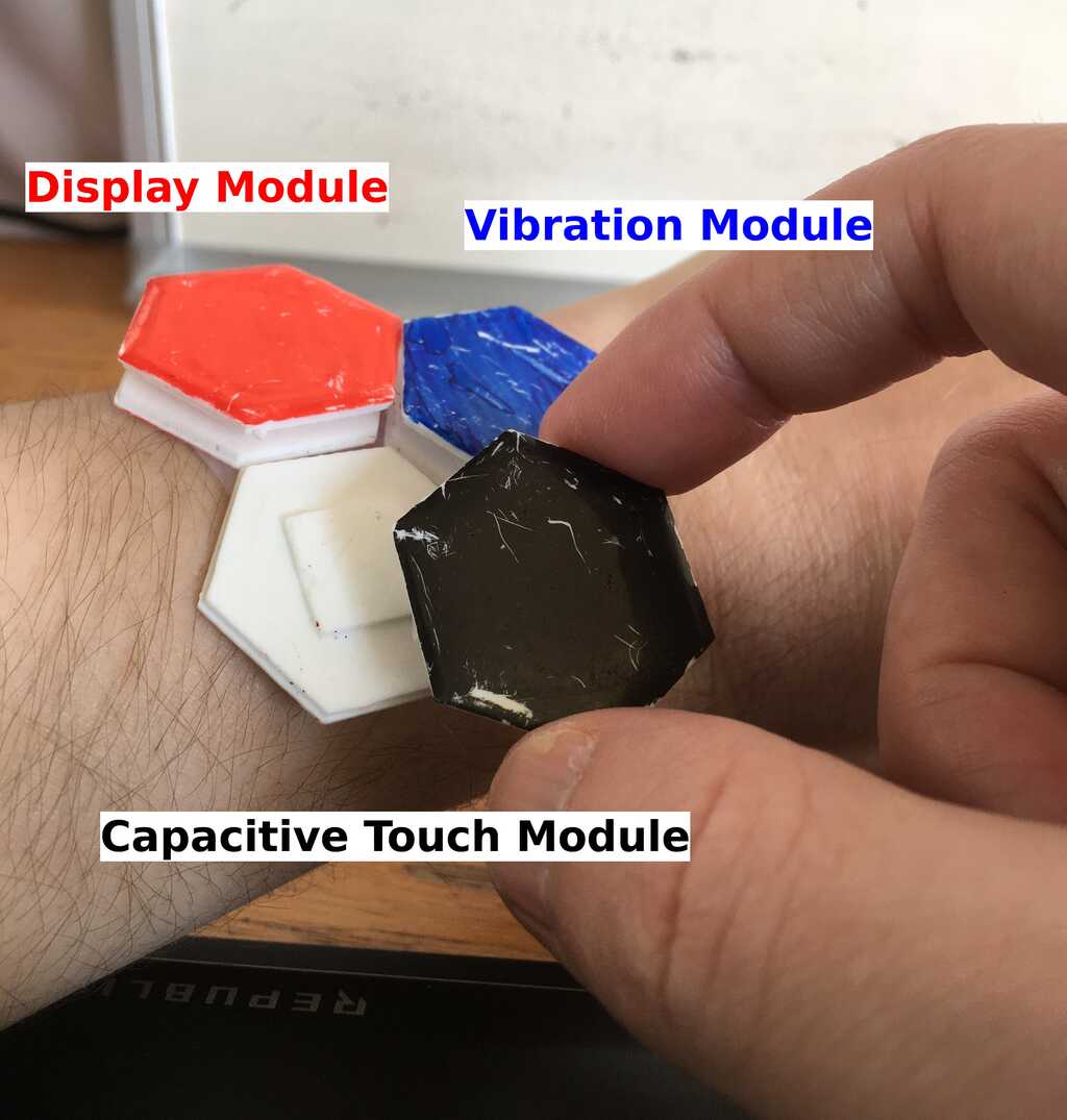
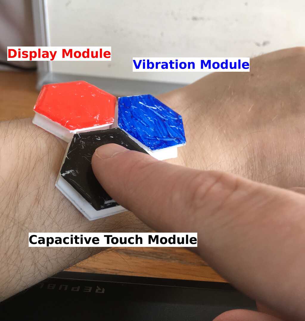
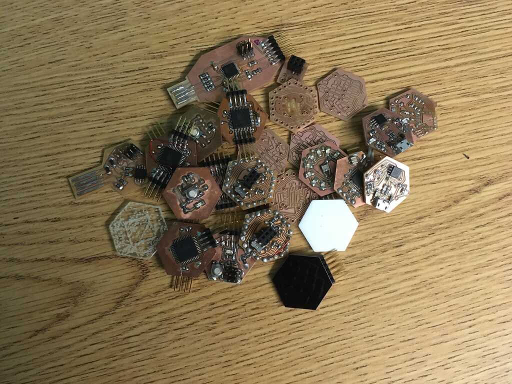
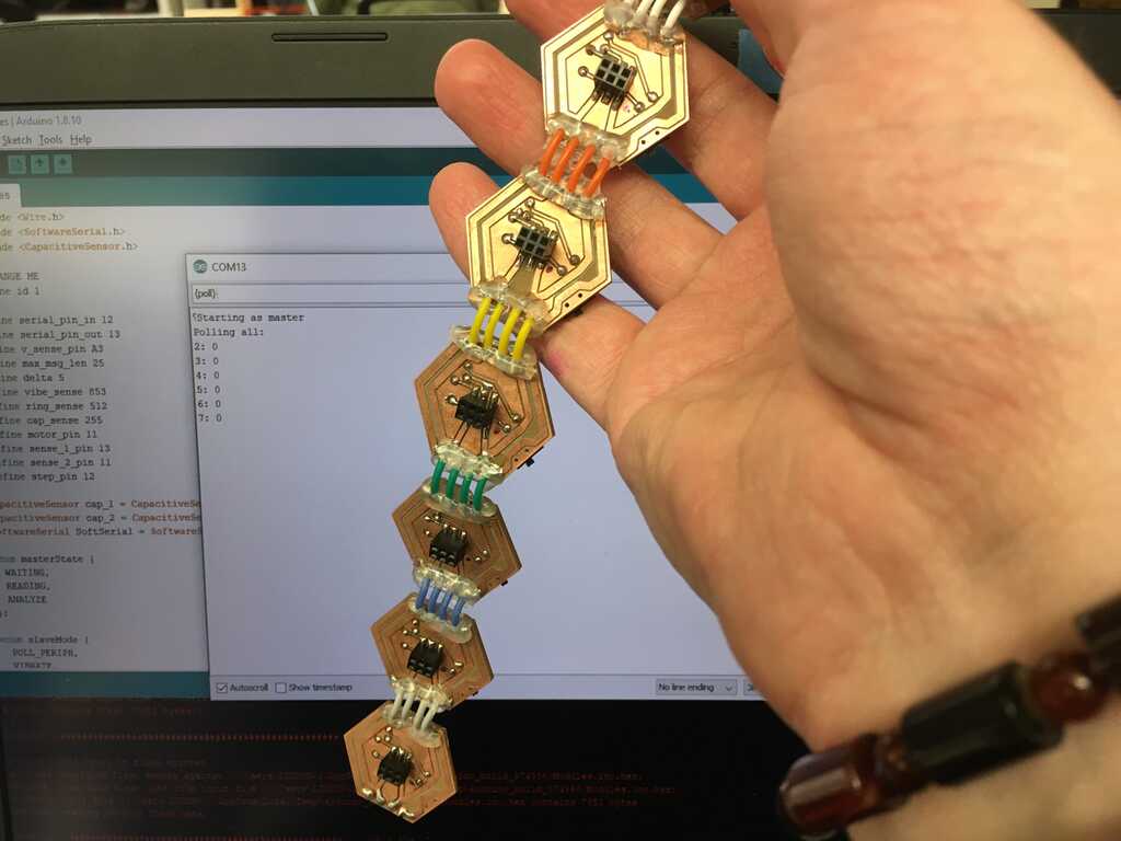
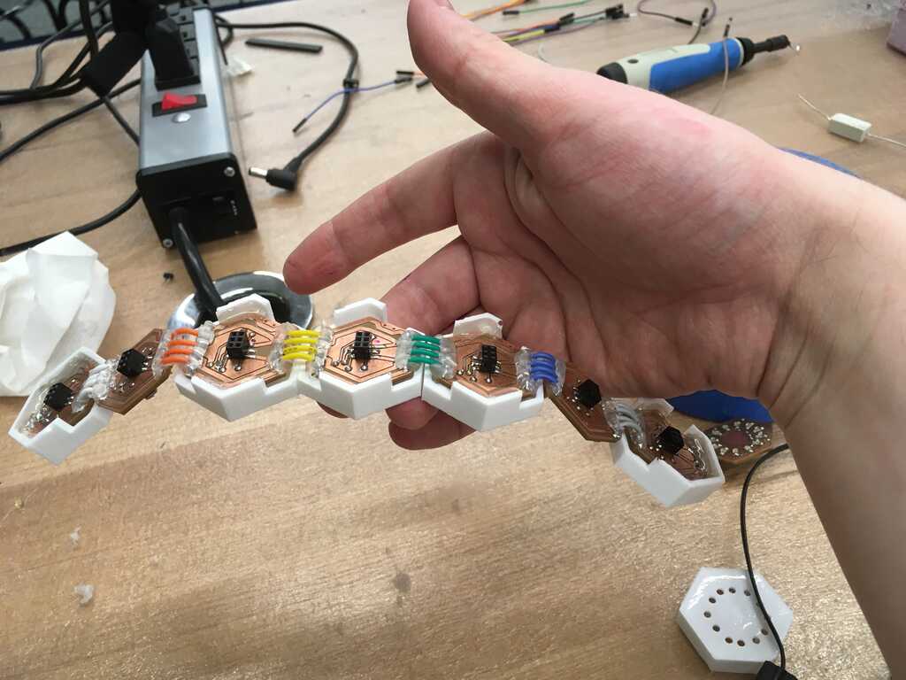
I had a hard time getting the two modules to work consistently, but I got one working perfectly. That was enough to convince me to go ahead and create the rest! Using Week 8's casts, I knew that I needed 7 modules to go all the way around my wrist, so I needed to fabricate 6 more (with the one that already worked). And with one hooked up to the FTDI, I could make one more each of the rest to fill out the wearable. This led to some satisfying patterning once again.
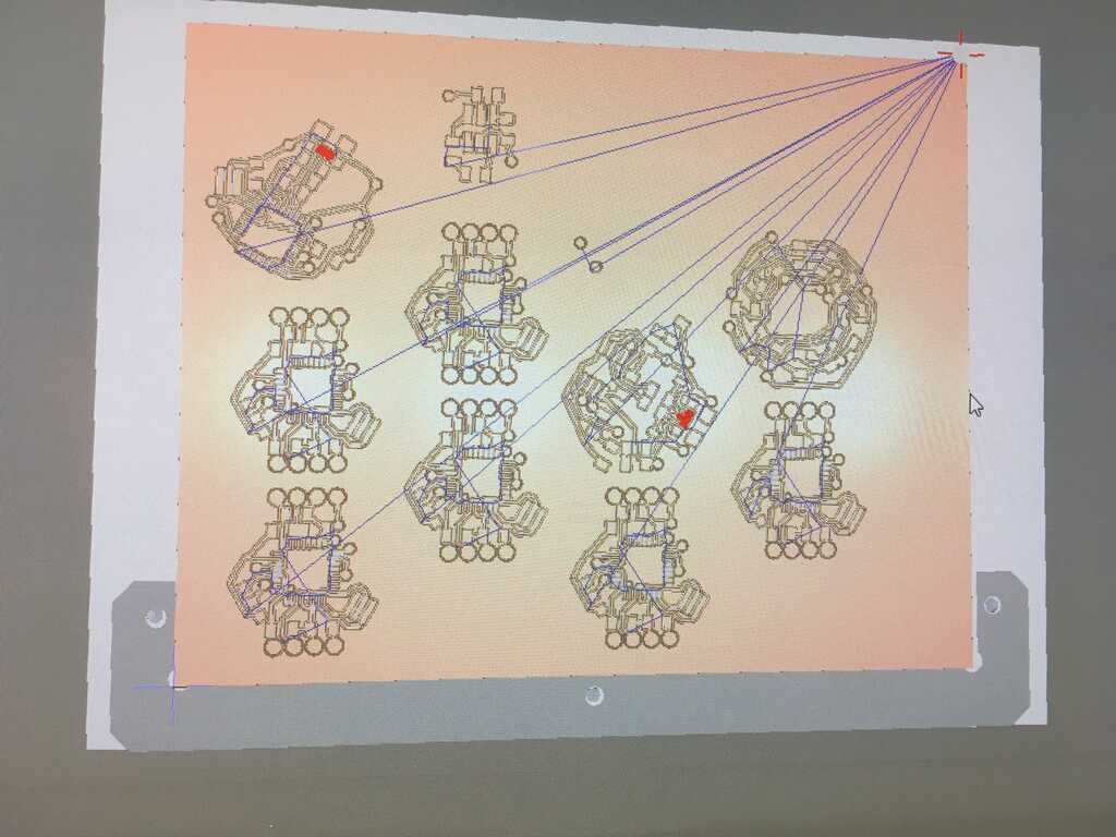
As Anthony described it, here's my hexagon army:
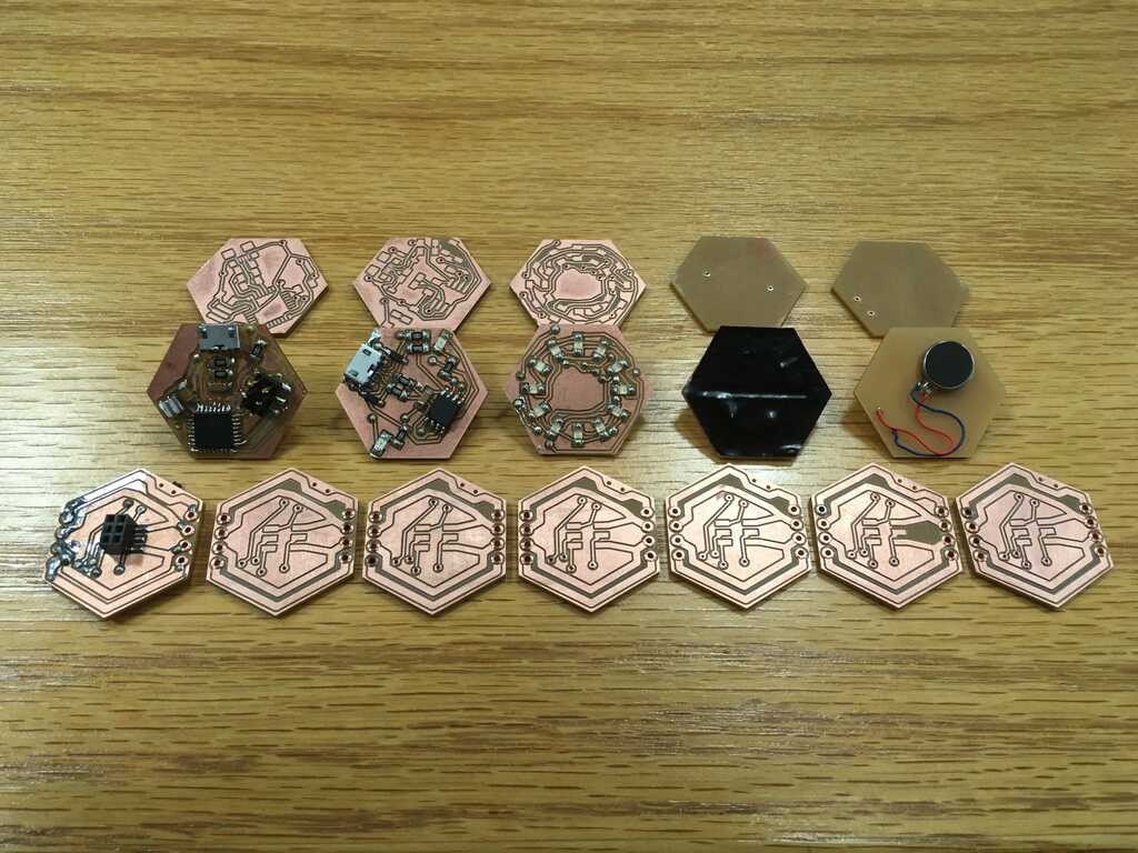
Unfortuntely, the person who had used the mill before me didn't set up the software properly, and totally destroyed one of the 1/32 endmills. The 1/64th I used ended up tearing up my board quite a bit, which led to a lot of post-processing (featuring tweezers, a small brush, and a microscope).
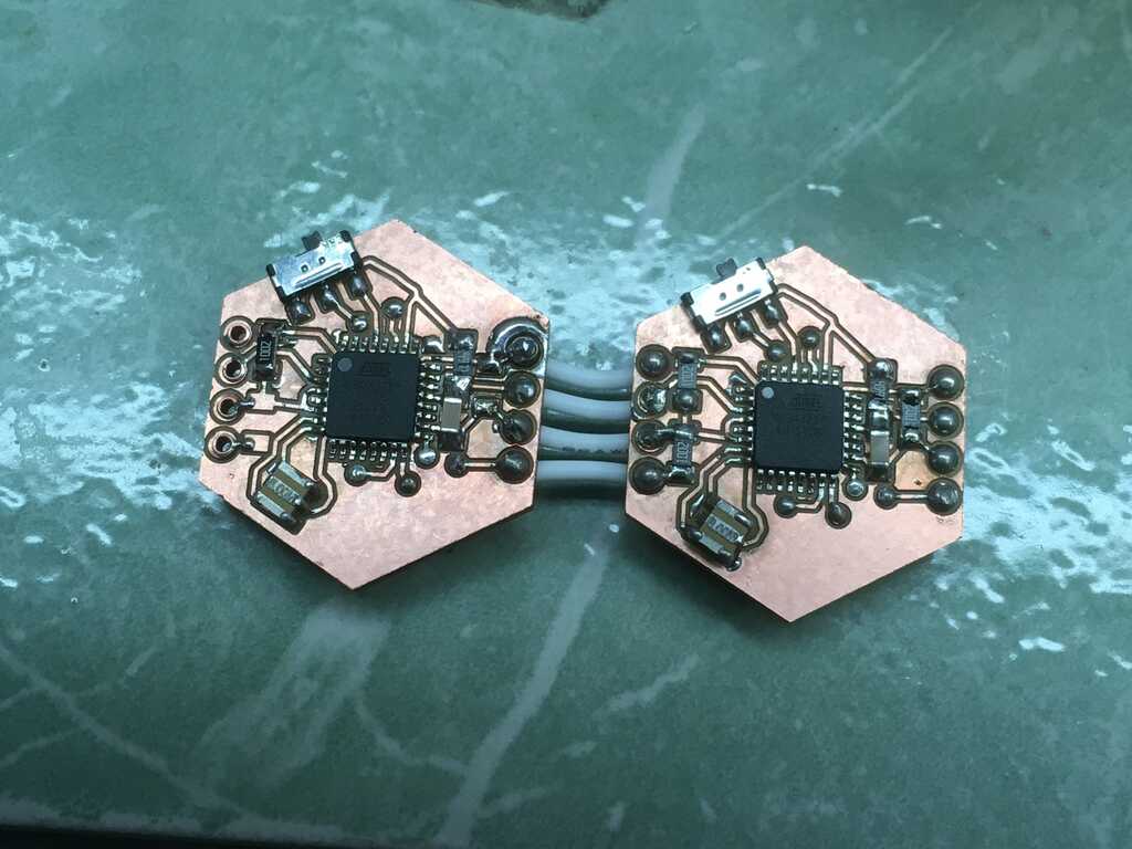
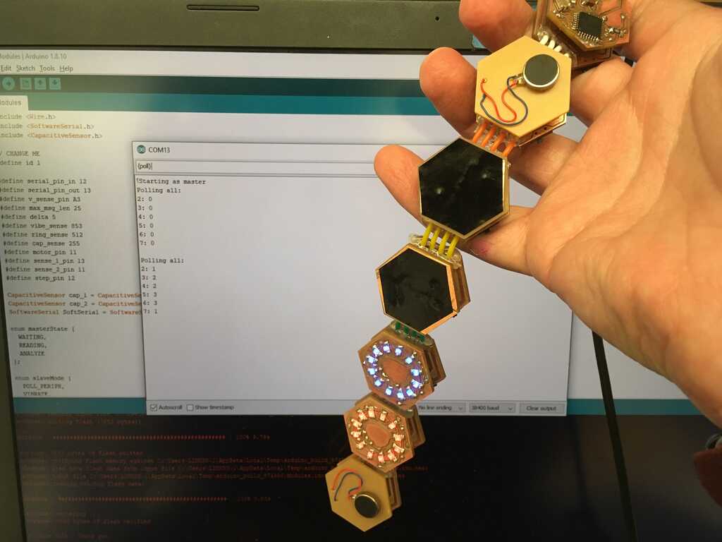
I made some different tweaks this time around. Rather than blue LEDs, I used red for the second display. I also one of the capacitive touch boards vertical, since the other was horizontal. Rather than using the vinyl cutter like in Week 9, I just used some scissors for these simple designs to save a lot of time.
And, after some stuffing, my army and I are one step closer to taking over the world
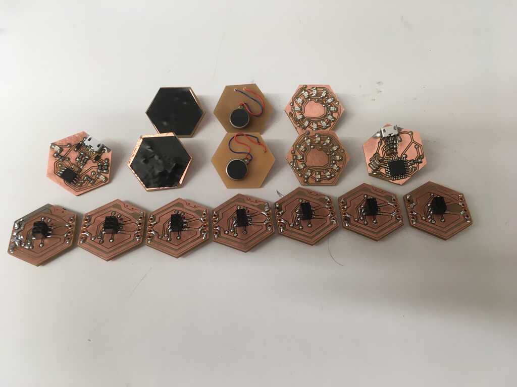
Before stringing the hexagons together, I tested each one individually. This involved another sketchy setup, but that's okay.
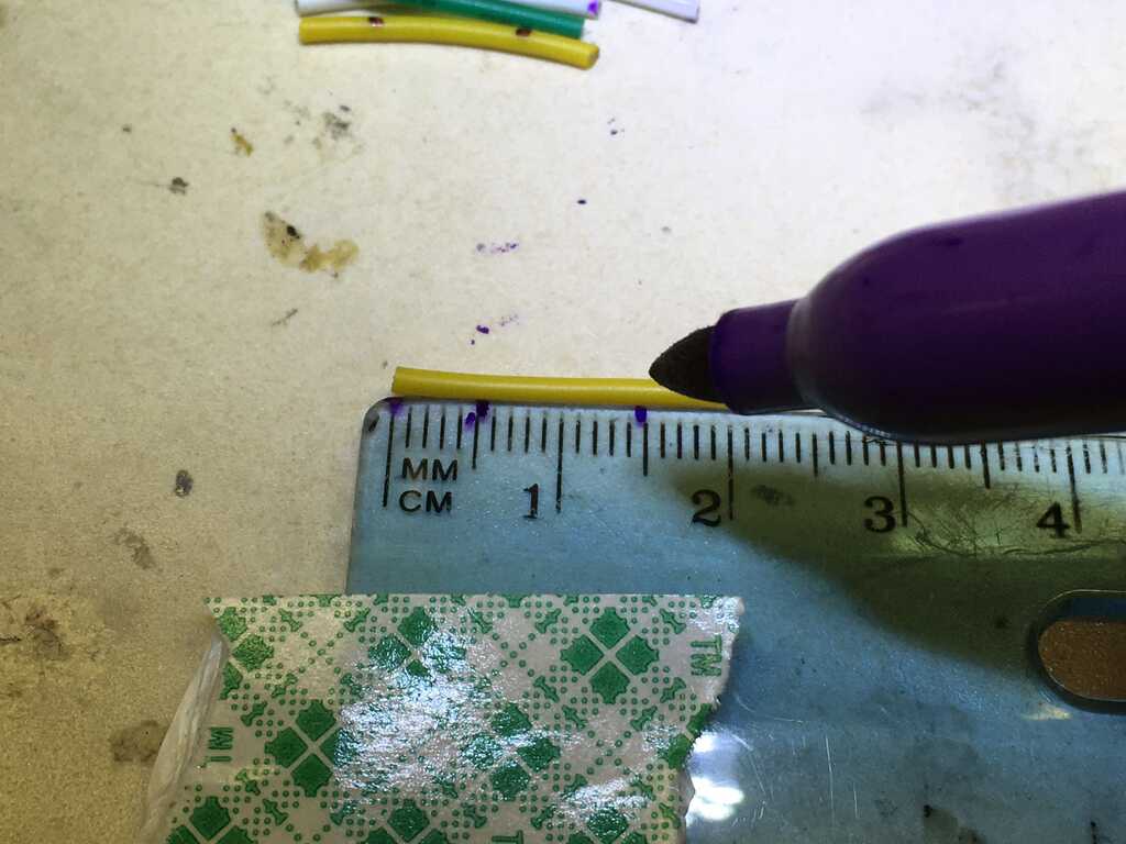
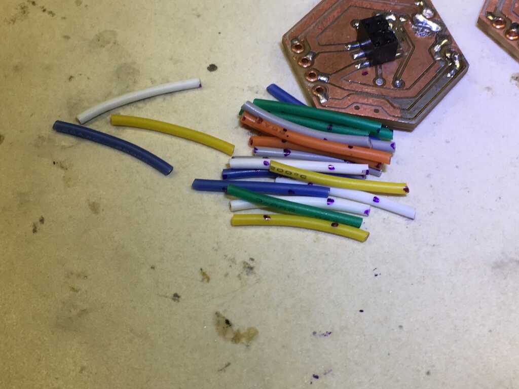
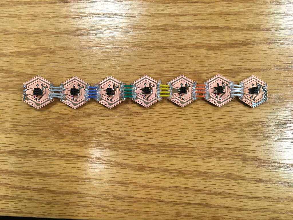
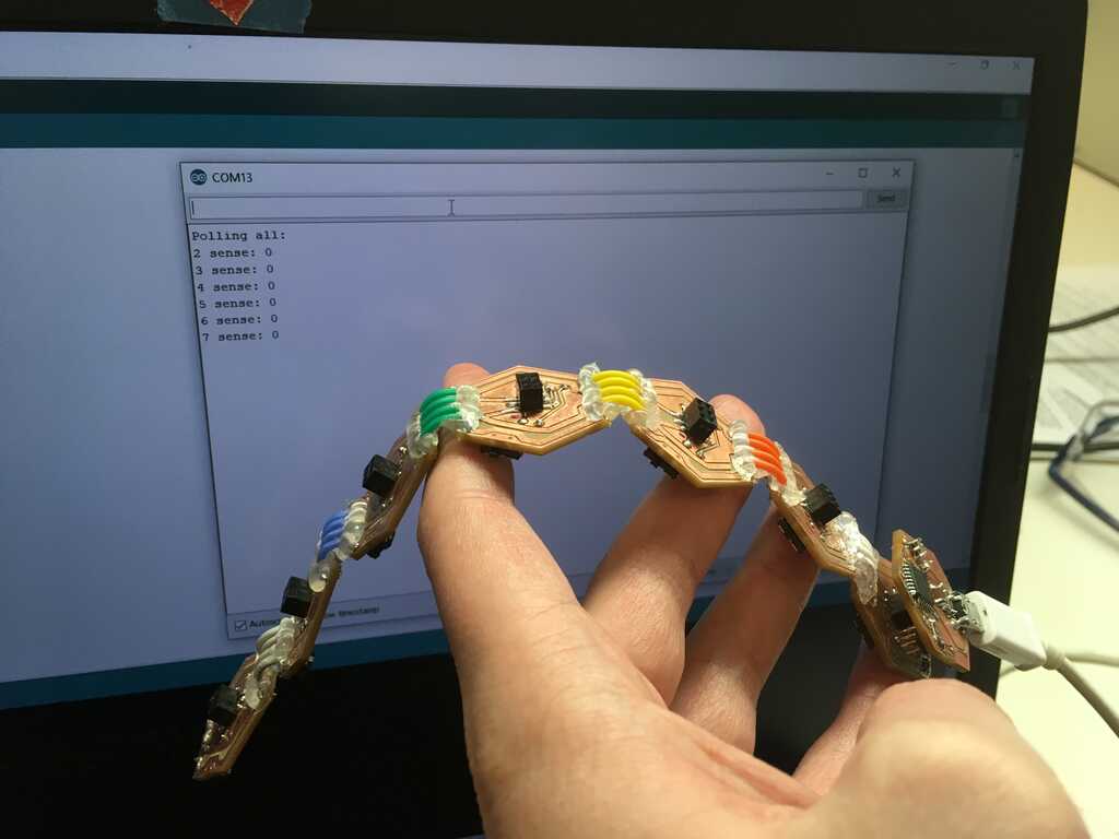
Putting the hexagons together was very similar to earlier, but this time around I had more colors. I also wanted equal distances, though, so I measured out 2cm chunks with 0.5cm stripped on both ends. I learned with the first version that the stranded wire tears out easily, so I added some hot glue to provide both insulation and some support to keep the wires in place.
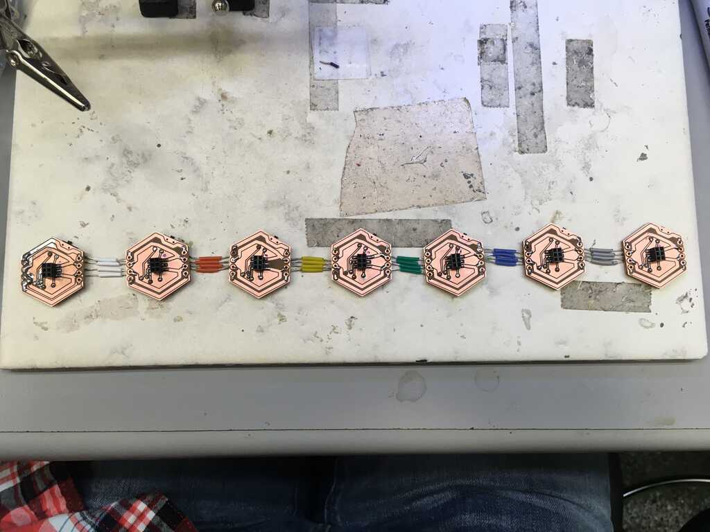
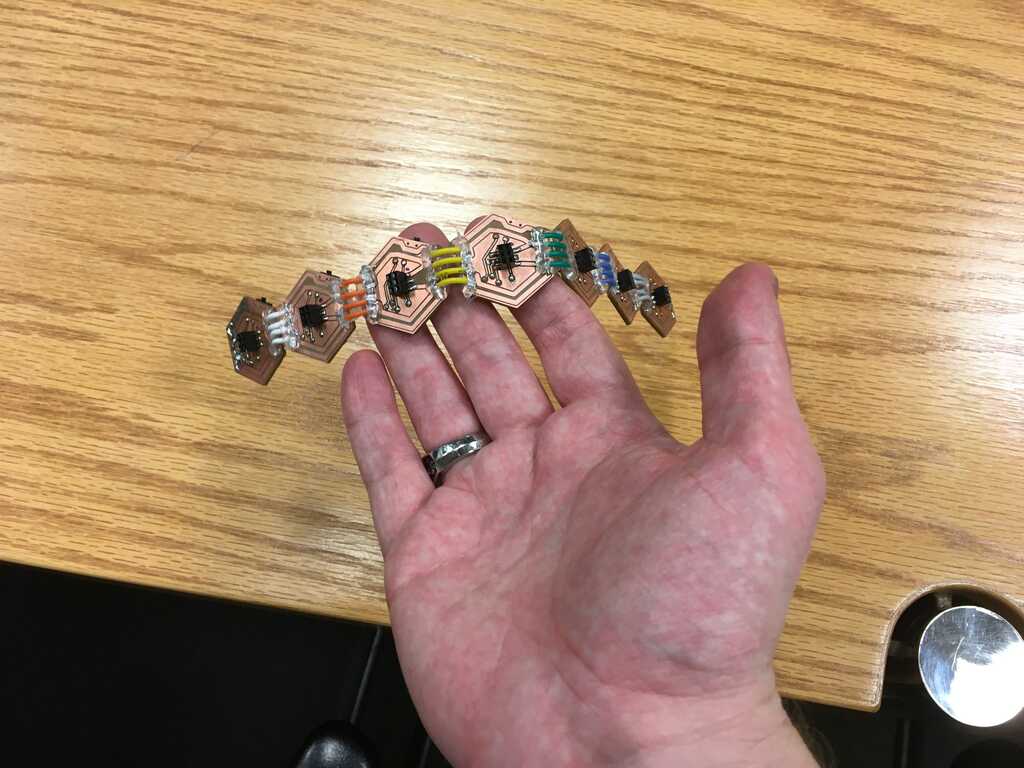
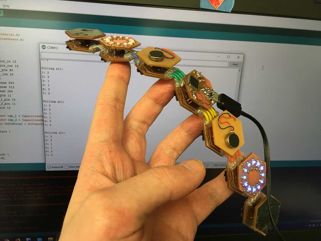
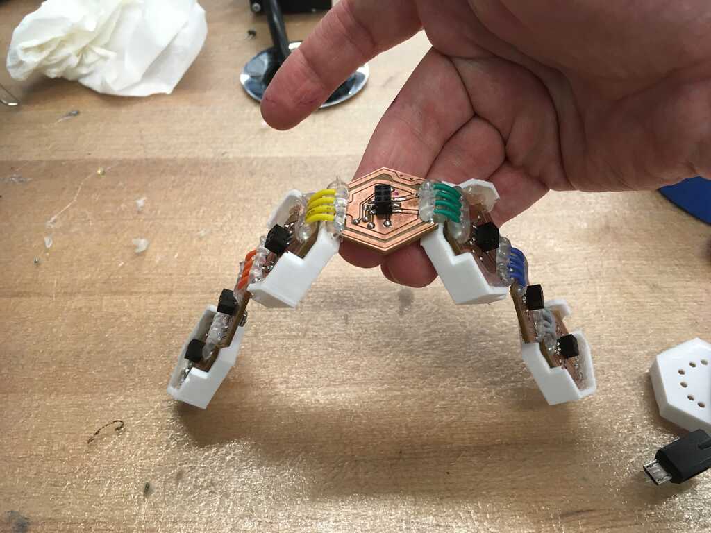
Once they're all put together, it makes for a nicely flexible strip of hexagons. Perfect!
And after that, the circuits are totally done. Let's explore some other aspects of the design process, like:
Programming
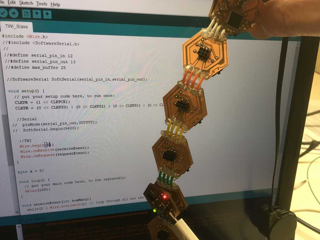
There were a couple things I had to do before getting started with this. One, was to figure out the workflow in C (very straightforward using Neil's examples under "Arduino"). The other was to figure out the workflow in Arduino, since Wire.h was going to be very helpful. Neil also has an example of getting started with the 328P in Arduino. In Arduino's boards.txt file, I had to add this:
module.name=ATmega328P, 3.3V, 8MHz external oscillator
module.upload.tool=avrdude
module.upload.protocol=arduino
module.upload.maximum_size=30720
module.upload.speed=57600
module.bootloader.tool=avrdude
module.bootloader.low_fuses=0x56
module.bootloader.high_fuses=0xD9
module.bootloader.extended_fuses=0x07
module.bootloader.file=atmega/ATmegaBOOT_168_atmega328_pro_8MHz.hex
module.bootloader.unlock_bits=0x3F
module.bootloader.lock_bits=0x0F
module.build.mcu=atmega328p
module.build.f_cpu=8000000L
module.build.board=AVR_MODULE
module.build.core=arduino:arduino
module.build.variant=arduino:standard
And make sure the programmer under Tools->Programmer: was USBTinyISP. To use this, I also had to use Sketch->Upload Using Programmer. I also did Tools->Burn Bootloader, but I'm not entirely sure that was necessary.
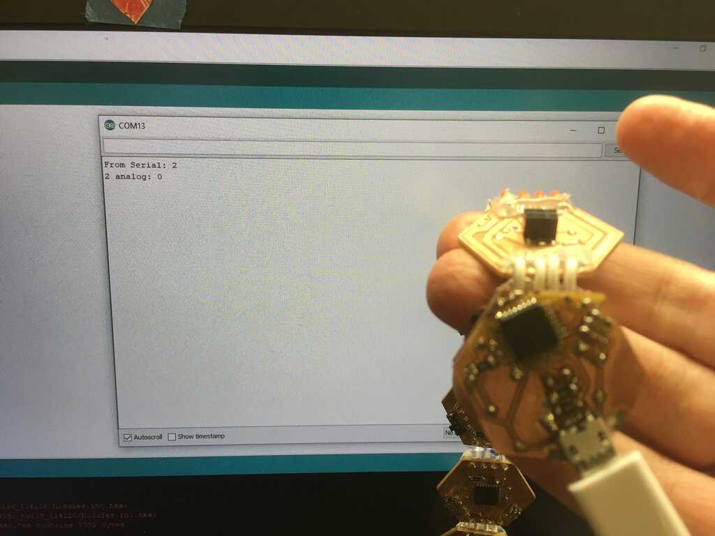
This came with a bunch of trial and error, and not knowing if it was a board that wasn't working or the setup. One of the two modules would work with avrdude, but couldn't work with Arduino, while the other (exact same) module would work with both. Oh well. I could program (with the other plugged into an FTDI for power)
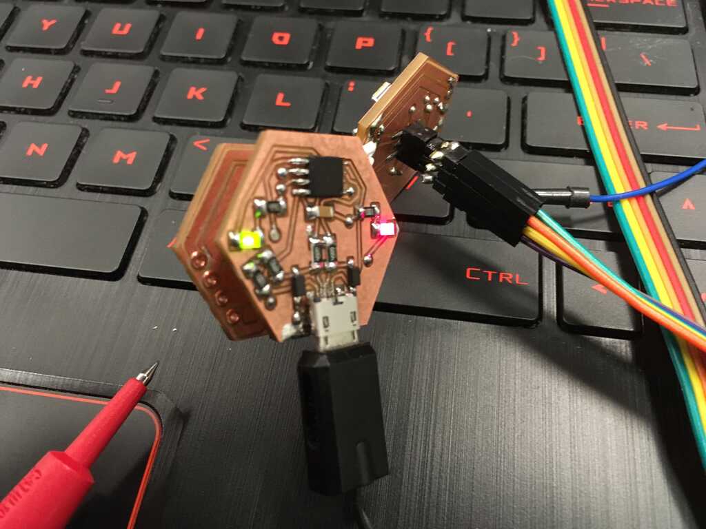
and sucessfully get data out through the FTDI board.
These were the successes that convinced me to go ahead with the rest of the boards.
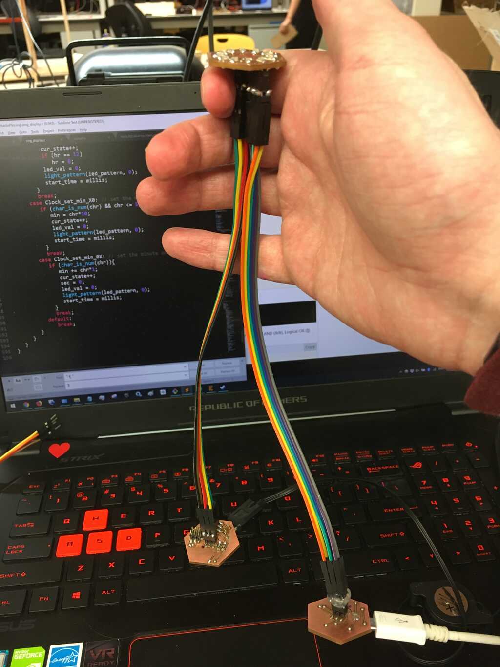
The programming setup was pretty straightforward: one board is plugged into the FTDI board, the programmer is plugged into a board, and the programming switch is flipped. It works like a charm.
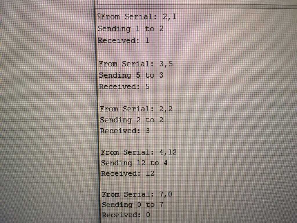
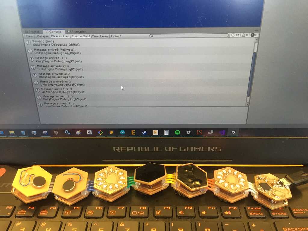
The code I was most worried about was the I2C network. Since I didn't get to it during Week 11 and it was critical for my project, I looked into it first. As it turns out, Wire.h makes this whole process very painless. These write and read tutorials show just how simple it is to ship bytes around. By assigning each module a unique id, I was able to write a bit of code that sent a number to a specified module, and the module would spit back the sum of all of the numbers it had received so far.
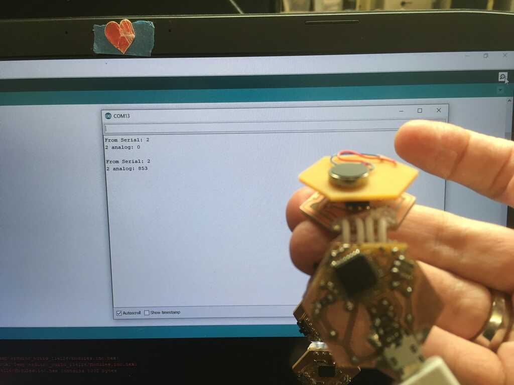
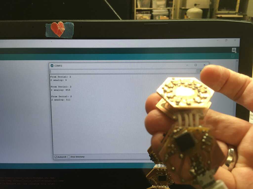
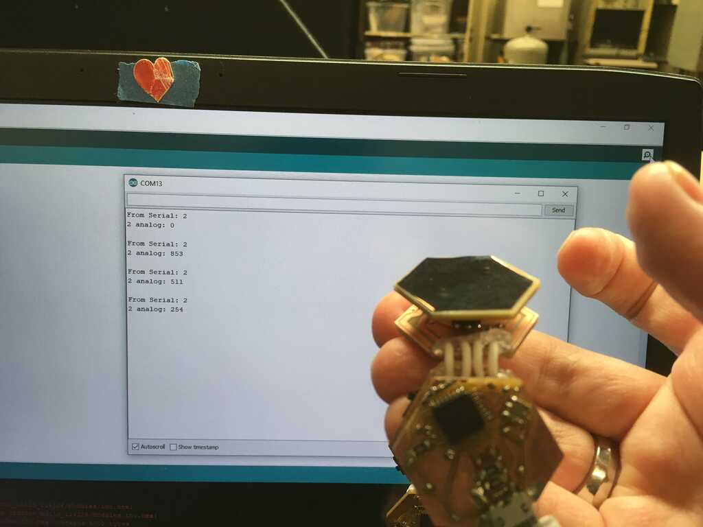
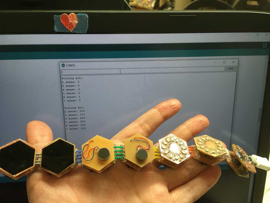
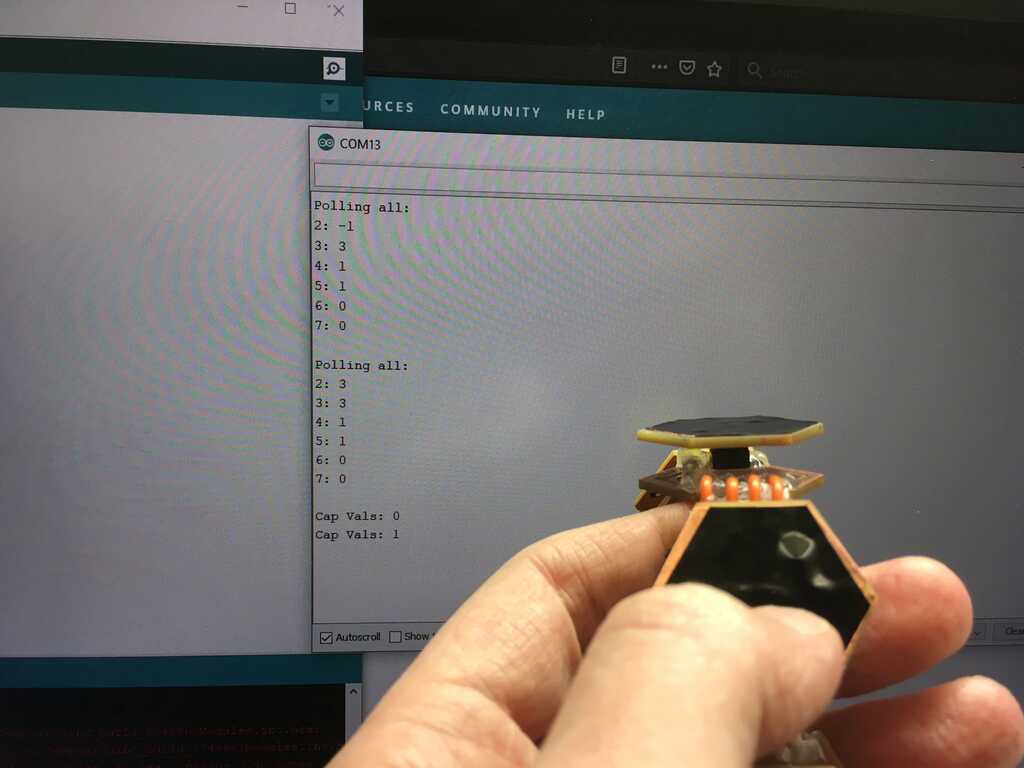
Thank goodness. Now I know that I can use I2C! With this in hand, I can start moving on to other things, like figuring out what Vsense values correspond to which peripherals! To do this, I took the two bytes from the ADC on a slave module, and sent them to the master module where I reconstructed it. Check it out!
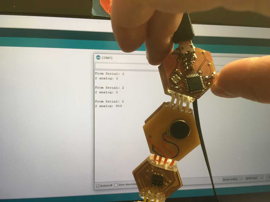
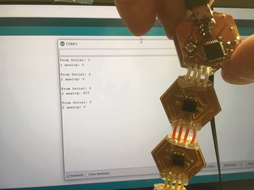
Since the modules are all running the same code, any one of them can be the master! The designation of slave and master starts when the modules boot up, and since the FTDI module is the power source, when it's moved, the modules will have naturally power cycled to the boot up sequence.
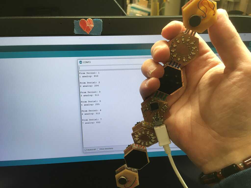
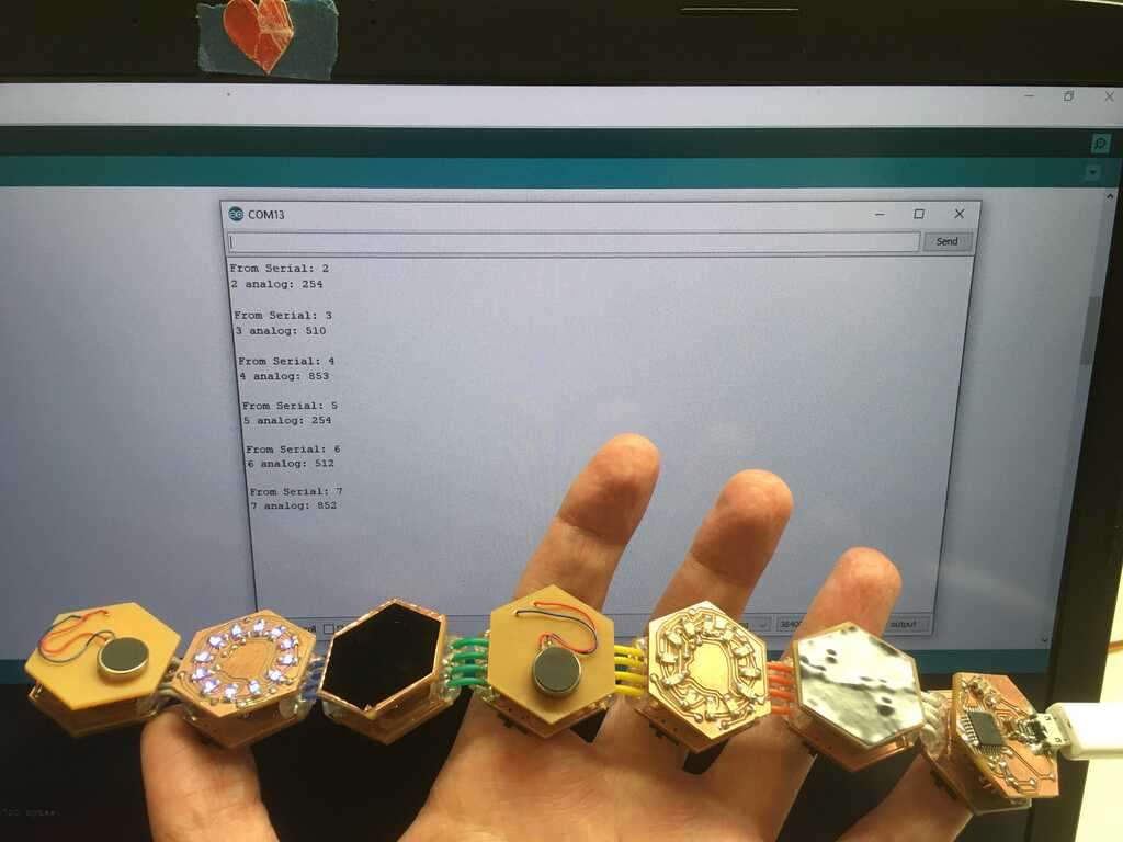
And since the modules check the ADC when requested, the peripherals can be swapped out at runtime. After collecting the data earlier, I know which analog values correspond to which peripheral. The value could sometime be off slightly, so I gave the readings a slight buffer. I then mapped those values to more meaningful numbers. Here, 0 corresponds to no peripheral, 1 to vibration, 2 to the display, and 3 to the capacitive touch.
Now that we've got this figured out, we can make our output a bit cleaner.
With this out of the way, we can get on to making the peripherals do stuff. The motor was pretty straightforward: turn on a pin. Done.
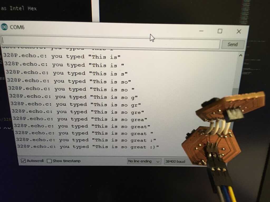
The display gets a bit more complicated. At first, I planned on using more I2C. But then I realized, why not just use serial? I was already using Arduino's SoftwareSerial, and the display (still running on C), used a Serial implementation to communicate. I needed to switch my baud rate from the 38400 the modules were using to communicate through the FTDI cable to my computer to the 9600 that the ATtiny44 on the display was talking at. I also had to keep in mind that the capacitive touch module would reverse the direction of the pins I was using for serial, so I reinitialized this 9600 baud rate serial every time the display module was plugged in. Great! I tried to send a character over to the display using SoftwareSerial.print() aaaand... Nothing happened. Well, that's no good. It turns out that the oscilliscopes in EDS have a serial reading function, so I used that to see what's going on.
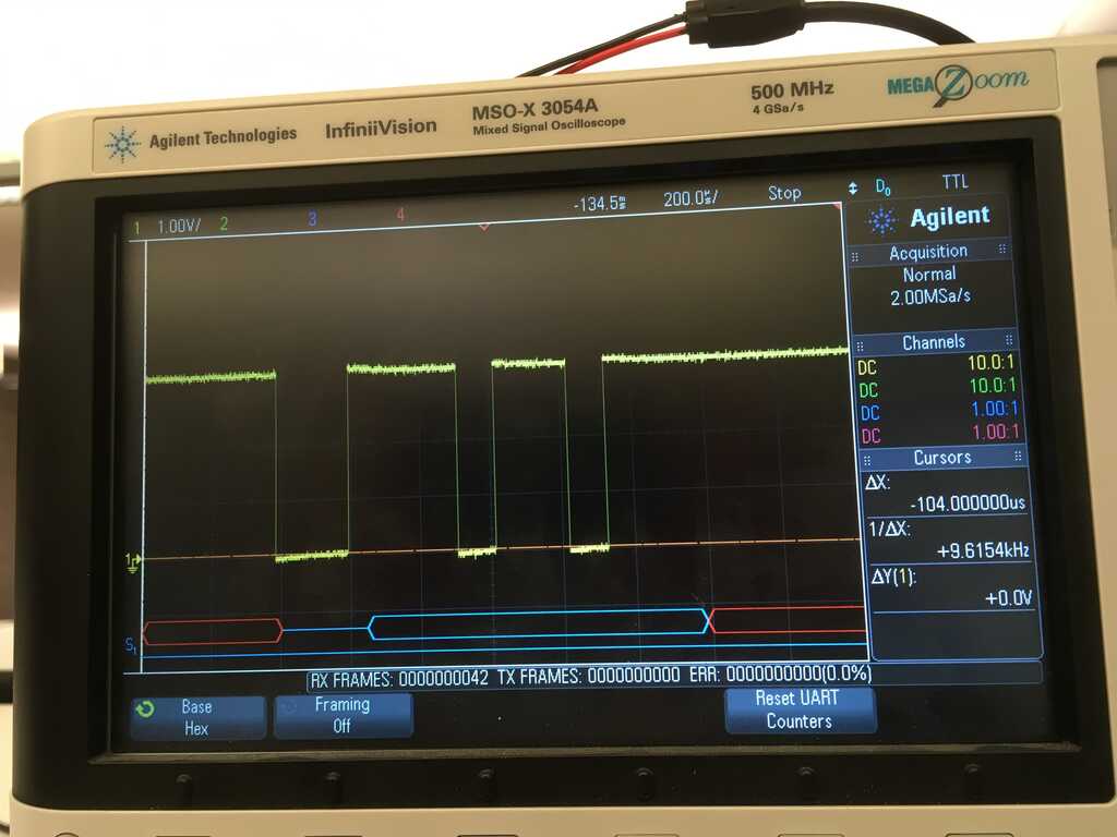
What you're seeing here is what the correct output should be for 'n', which should always trigger a response on the display. Instead, I was seeing multiple characters being sent out on the scope. Why? Because I was requesting the data as a byte (110) rather than a character. It turns out that SoftwareSerial.write() is what I should have been using. It will send the raw byte you give it. Using that instead gave what you're seeing in that scope shot. Perfect! However, since I'm operating on bytes now, I decided to change the codes for the display from characters to lower byte values:
0 - Set
1 - On
2 - Off
3 - Toggle
4 - Notify
5 - Echo
6 - Pulse
7 - Ring cc
8 - Ring cw
9 - Stars
10 - Clock
66 - Notify
Being able to send a byte made setting the time easier. Rather than sending 'c'->'0'->'4'->'5'->'8' in order to set the time to 4:58, I can now just send 10->4->58 and be done. Because of this, notify needed to move to a higher value than 59 in order to avoid terminating setting the clock early. And what better way to notify someone than to execute order 66? Of course, this also meant that I needed to program the display. I did so like this:
I didn't realize it until I went to start writing code for the capacitive touch sensor, but none of the pins on the header actually have an ADC (except for the Vsense pin, but that's in use). Instead, I found this library that allows you to measure capacitance on a digital pin. Phew! Crisis averted. Using it, I can tell which side of the capacitive sensor is being touched. I went with 0 for neither, 1 for one of them, 2 for the other, and 3 for both.
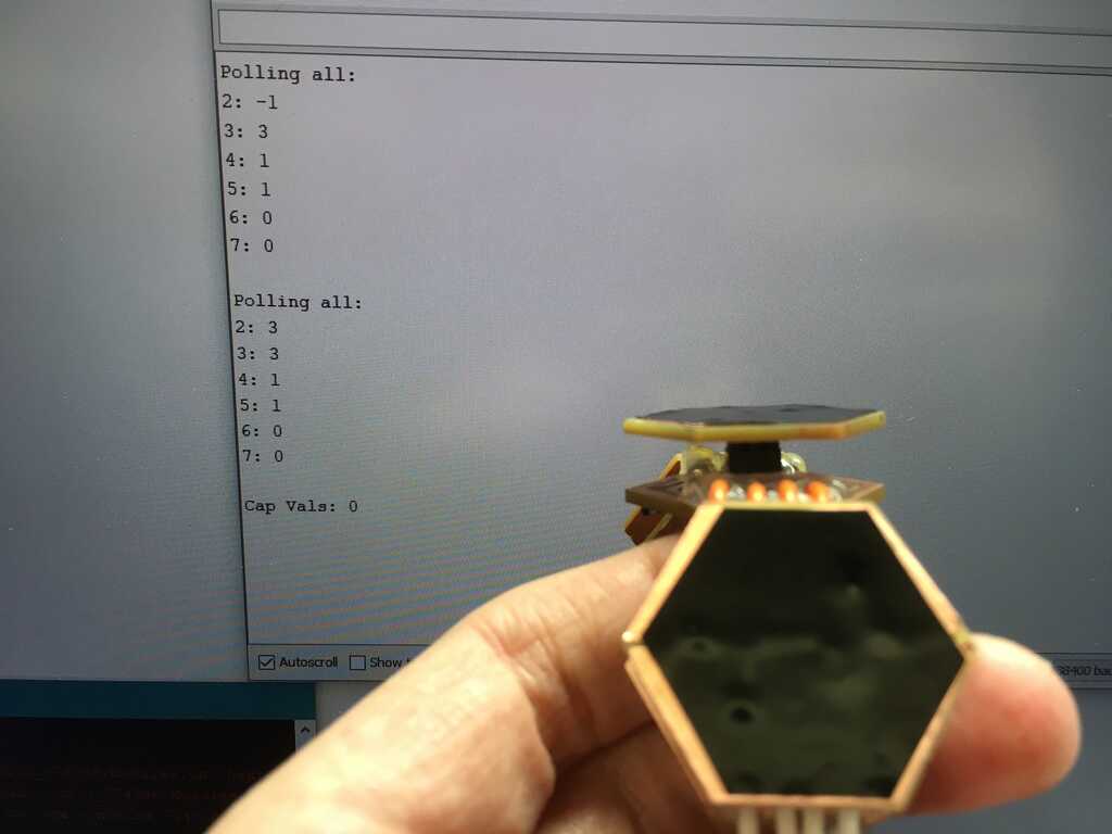
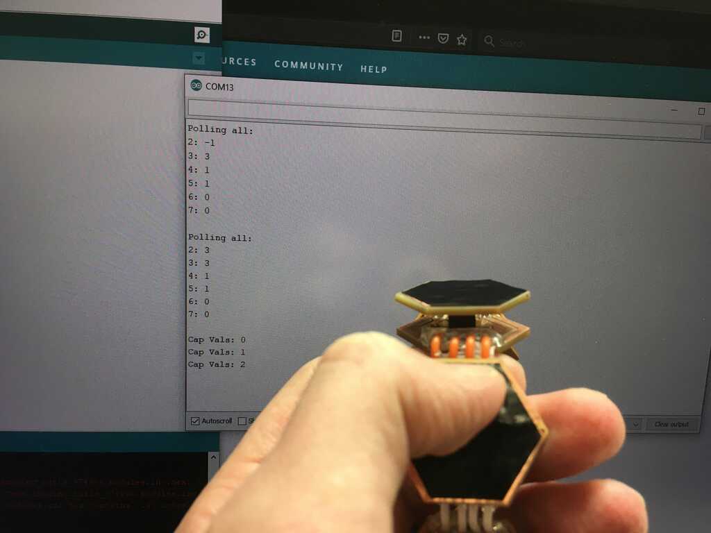
With these changes, I also cleaned up the polling a bit more again
When it came to the interface, I completely changed what the modules sent back through serial, where they'd output something like 4,0,2, where module 4's peripheral(0) is a capacitive touch sensor(2), or 4,2,3, where module 4 currently has both of its capacitive touch (2) sensors being pressed (3). While more difficult for a human to read, it's much easier for the interface to read.
Packaging
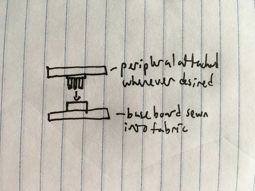
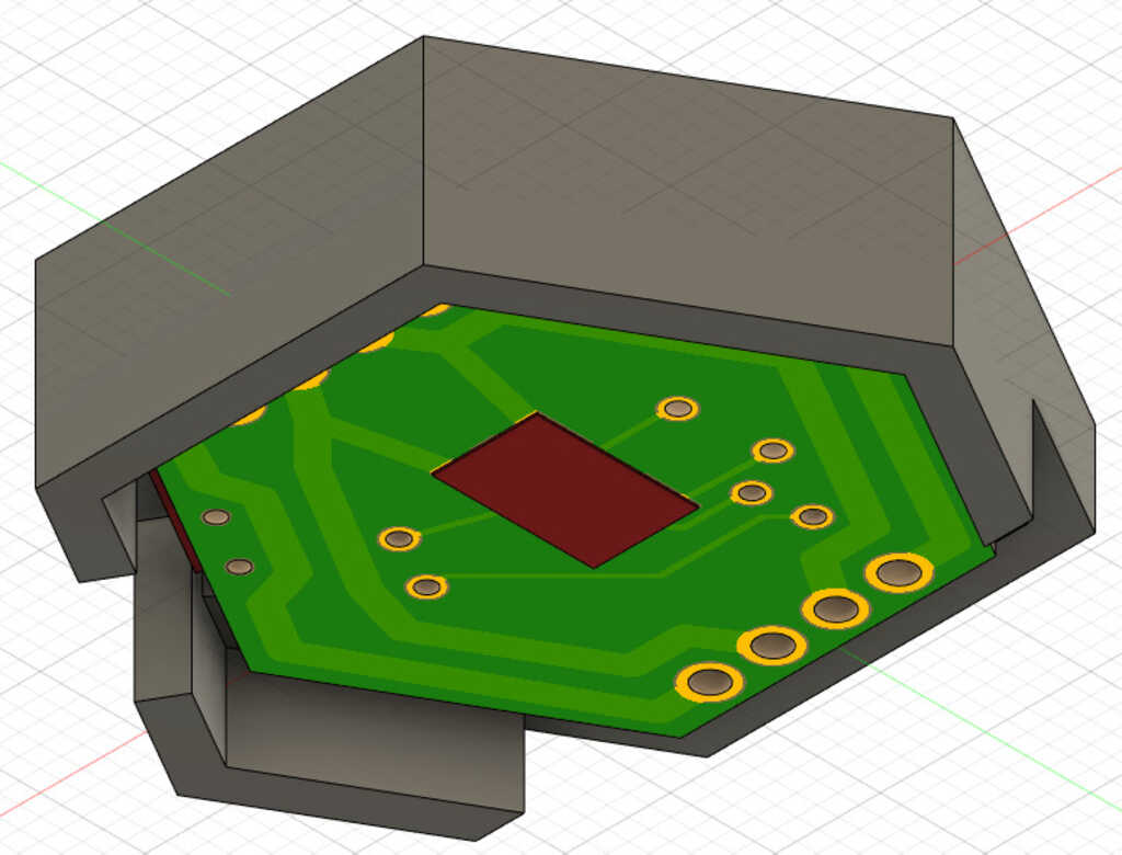
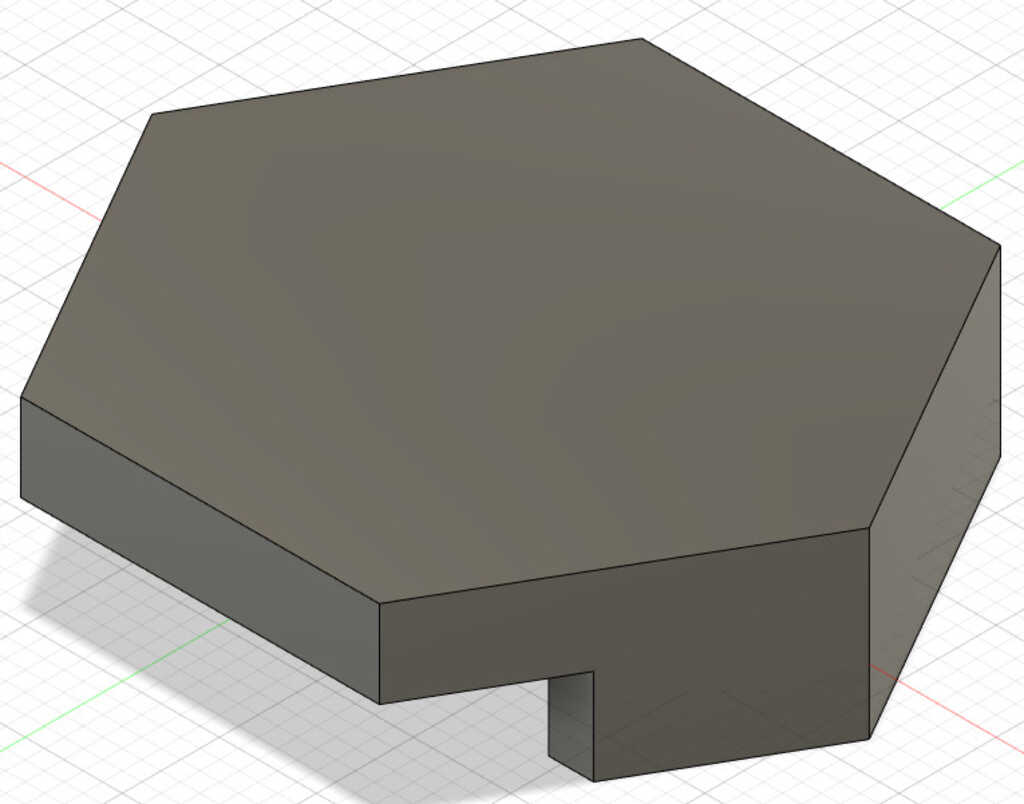
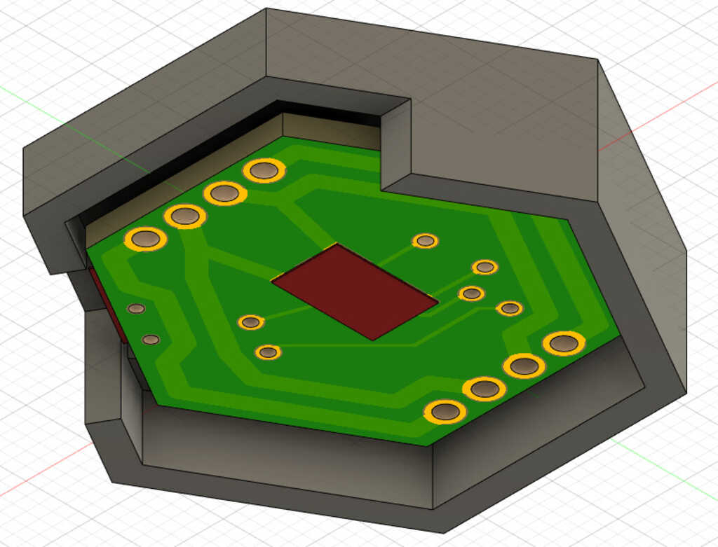
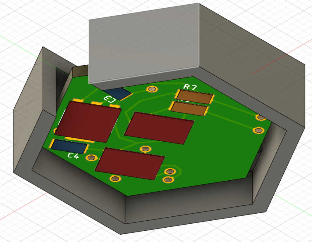
Who would wear a wearable that's just a bunch of circuits strung together? (Well, probably quite a few people, but still.) We gotta wrap these guys up. In Week 8, not only did I learn molding and casting, but also how to send circuits from Eagle to Fusion. This made my life much easier when designing cases for the modules and peripherals.
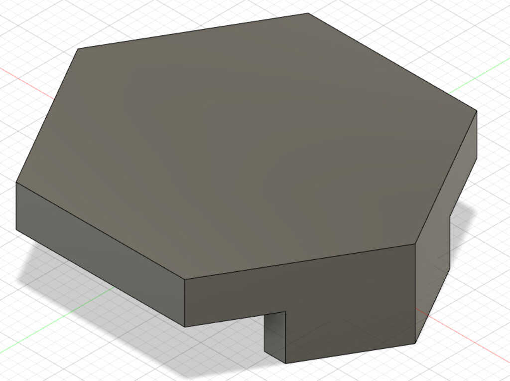
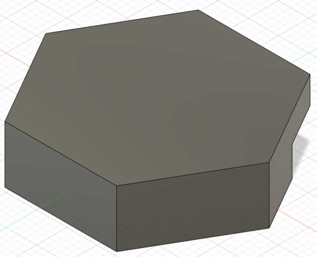
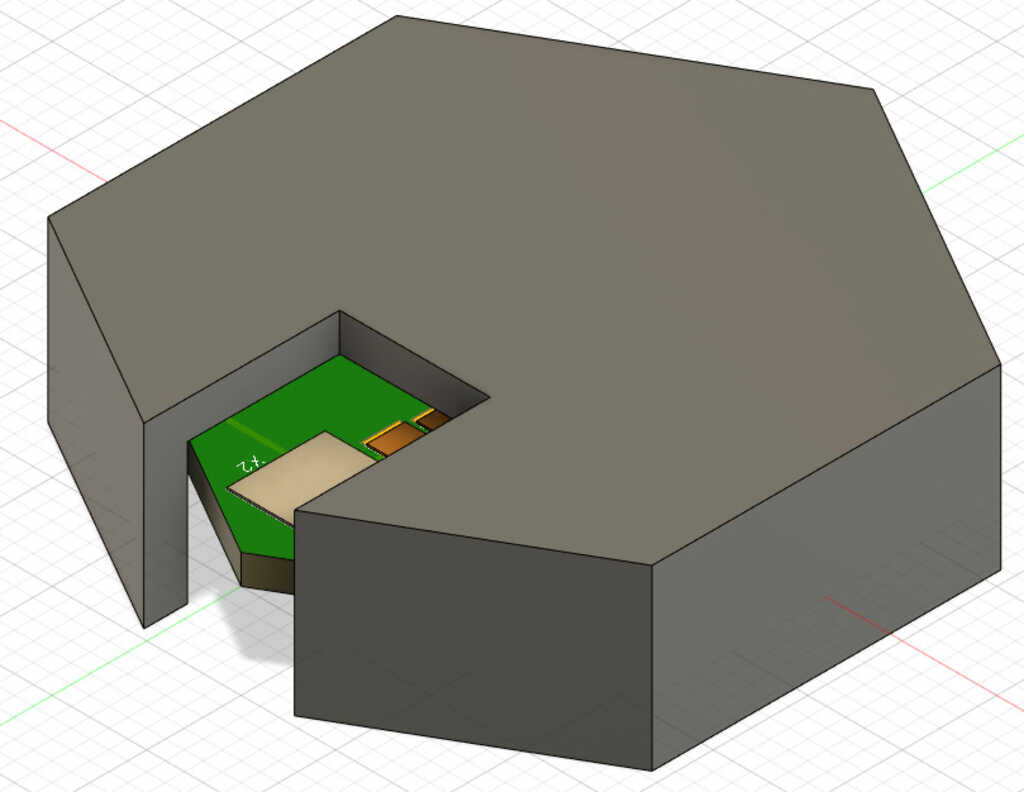
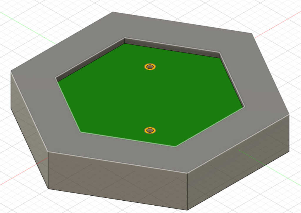
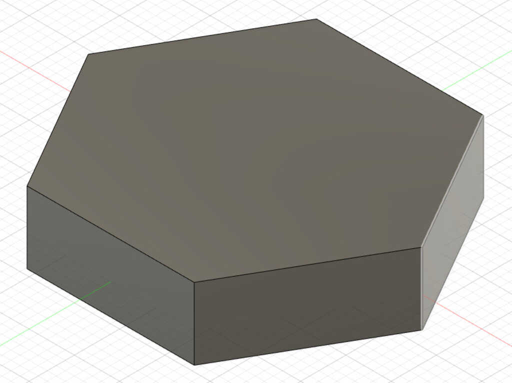
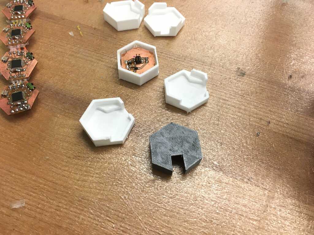
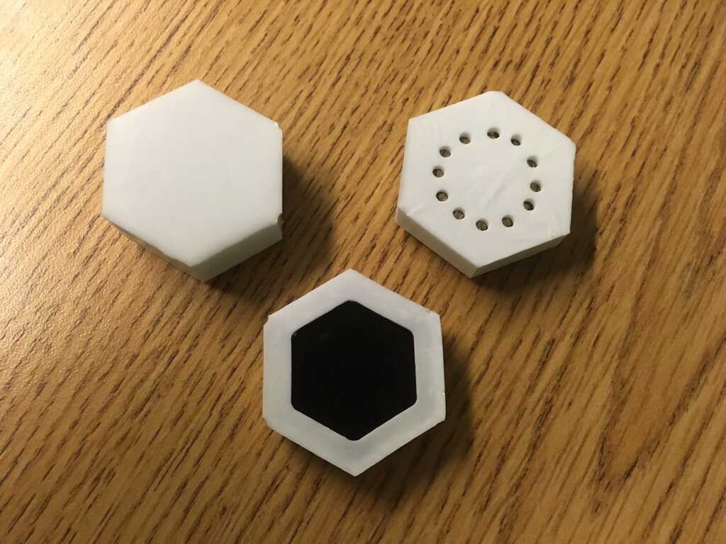
First up are the module cases. The cases in the middle need both sides open for the wires to get through, while the cases on the end only need one side open. That meant I needed three total designs. I originally considered trying to incorporate slots into the design for fitting the modules and peripherals together, but I decided against it for simplicity.
Next was the FTDI case. The only real design consideration here was for the USB micro header. I forgot to make space for the actual cable itself, but I resolved that later.
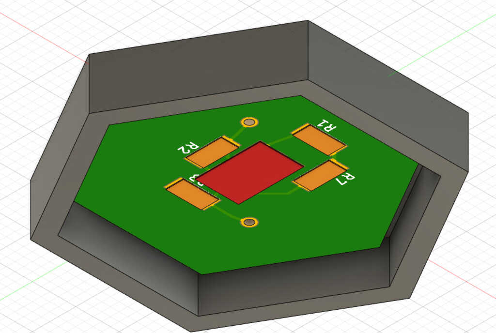
The capacitive touch case needed a window on the top so you can, you know, touch the capacitive touch pads.
The motor case just needed some extra space up top for the motor to sit in. If I had standardized where I was going to adhere the motor, then I could have made the case a better fit.
The display I planned on doing with a clear material, so I completely covered it.
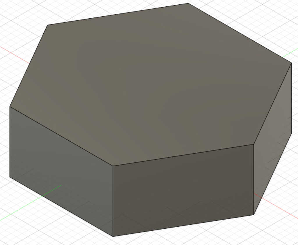
Now, how was I going to make these? I could just 3D print them, but that could end up taking a long time. Why not take some of the skills I learned and make a mold and cast them? First I gotta place the cases into a block so I can mill it:
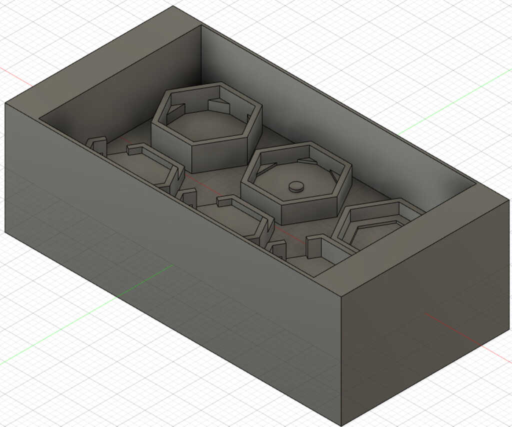
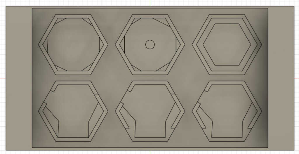
There was only space for 6 cases, so I decided that I'll 3D print the FTDI case since I only need one anyways.
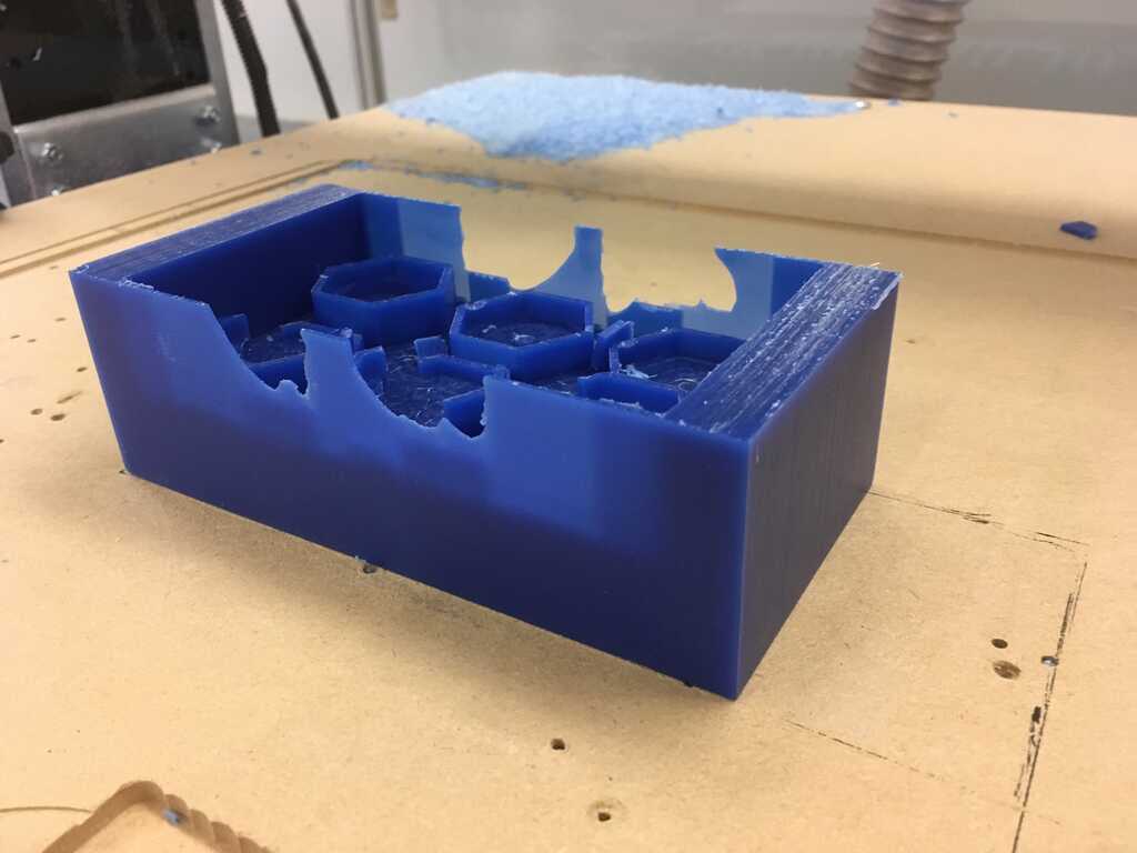
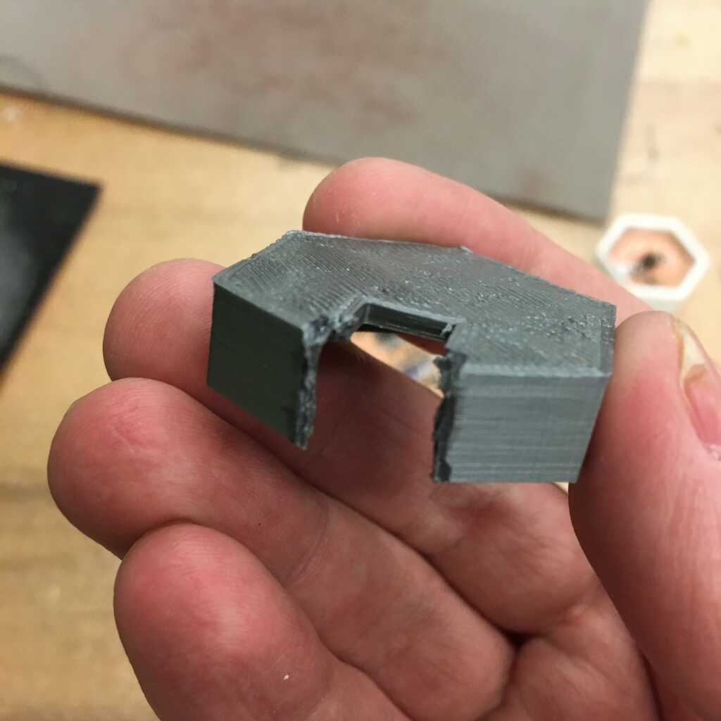
Now, milling it was going to be tight. I used both a 1/4 and 1/8 end mill to get the job done. Unfortunately, the walls were too thin and got a bit destroyed.
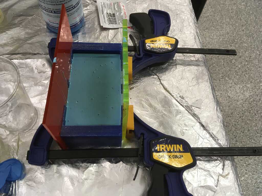
Fortunately, this is an easily resolved issue. I put acrylic on the walls that got destroyed, and clamped them to the wax. I poured the Oomoo in and it worked just fine, no leaks.
For most of the cases I used Smooth-Cast 305, but the display I used Smooth-Cast 326. Or at least I tried to.
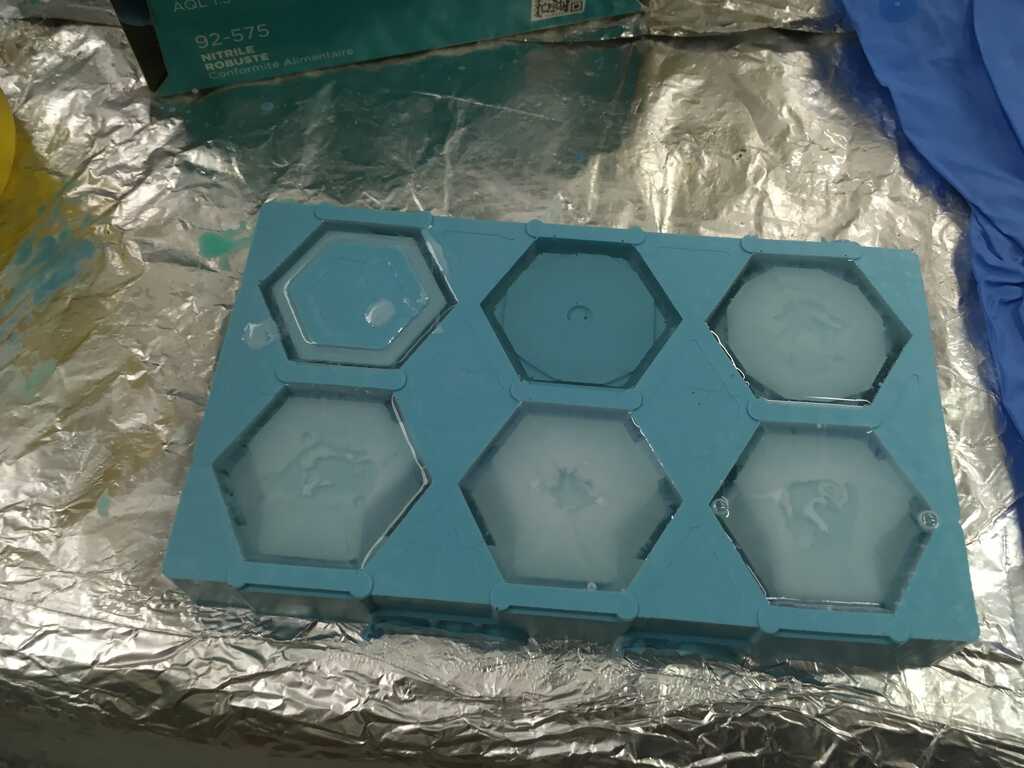
The first batch came out pretty well, except for the 326. It just wouldn't cure. On the next batch, I started using the 305 for all of the parts.
Meanwhile, I set about 3D printing the FTDI case on a Prusa. The gap for the micro USB header was fine, but it didn't fit the end of the cable. To fix this, I carved out a little more space so everything could fit.
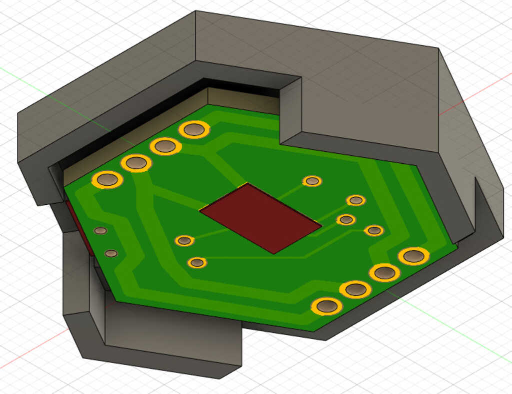
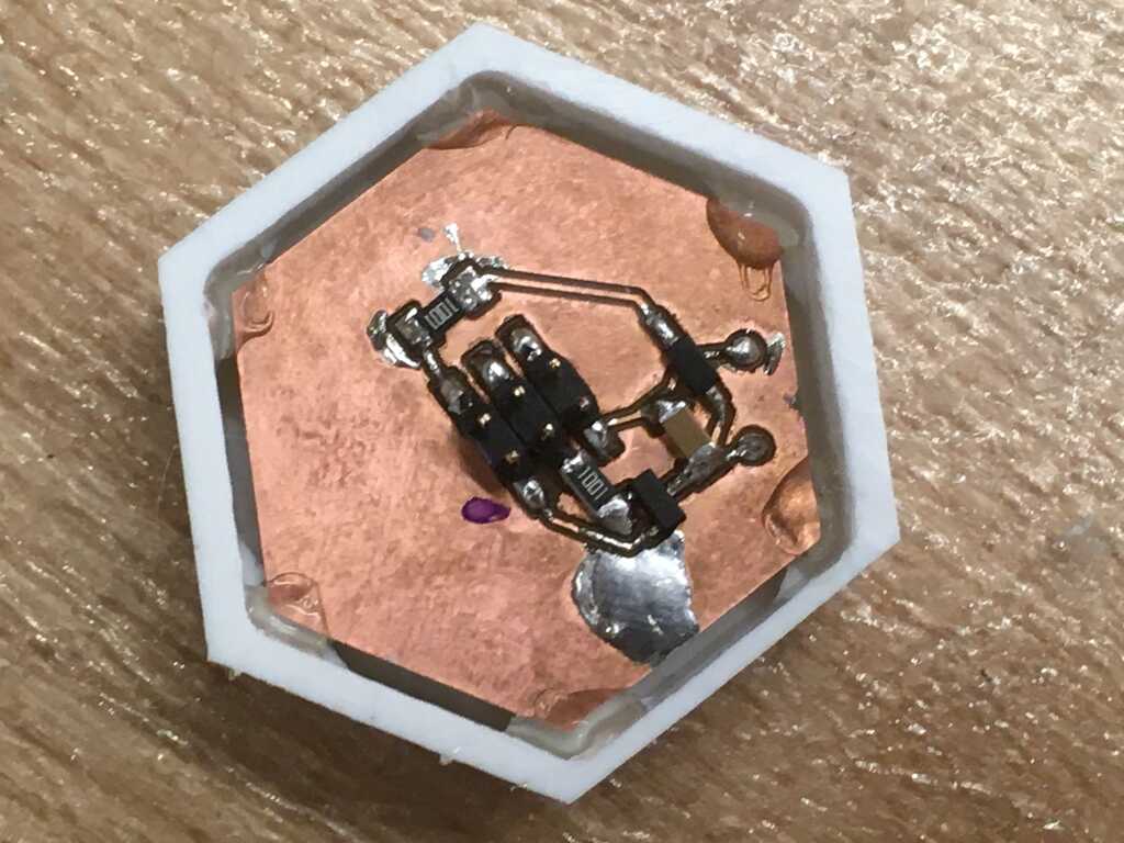
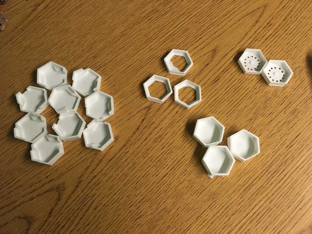
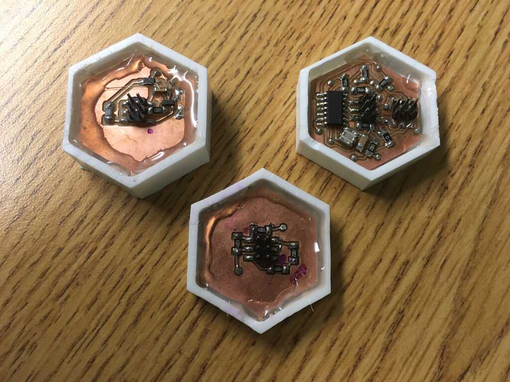
Next up was to get the circuits into the cases. I designed the cases with little standoffs so I didn't have to worry about vertical alignment, but I left a 1mm gap on all sides, which made alignment slightly tricky. I first put dots of hot glue in the corners, and quickly made sure that the circuit was correctly aligned before it cooled. Once it cooled, I caulked around the edges with hot glue to make sure everything stayed together.
Just some cases hanging out, waiting for the next batch to cure
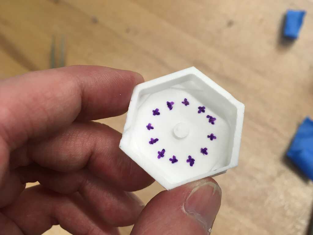
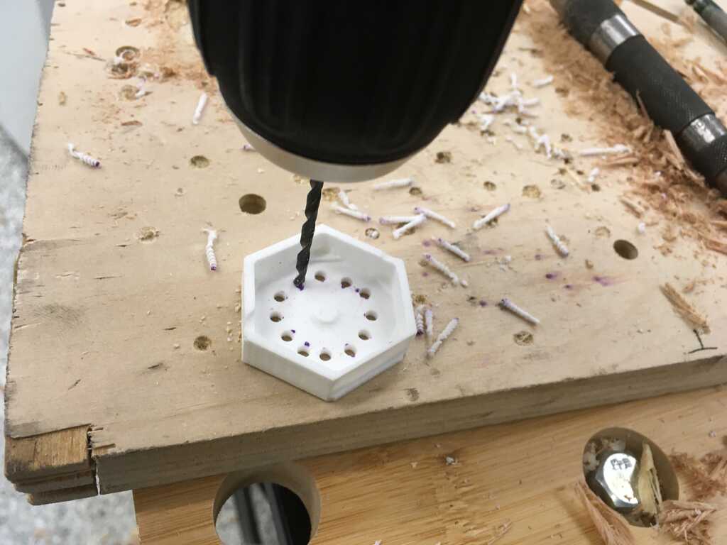
With the next batch that came out, I needed to figure out how to make the display case work. I first tried to use the capacitive touch case, but there were features on the display board that made it not quite fit. Up next, I tried sanding the top of the case to make it more transparent.
That didn't really work, but it guided me towards what did. By shining the display through the top of the case, I was able to mark where the LEDs were. And using those markings, I drilled holes to see the LEDs through.
Every time I messed up, though, I'd have to make another batch. While I didn't necessarily have to create an entire batch every time, it was much easier to get the proportions of 305 correct when mixing up slightly larger quantities, and I didn't want to waste what I mixed, so I ended up with these, in addition to the ones that went on the wearable:
And here's some closeups:
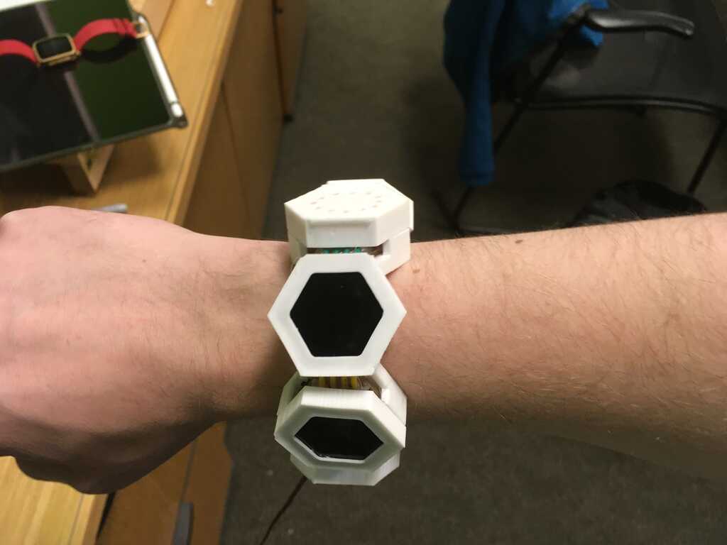
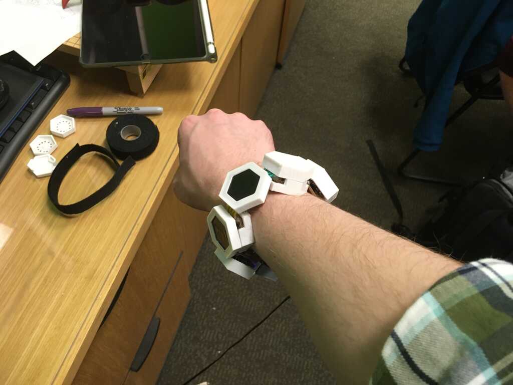
Only after casting a bunch and starting to glue did I realize I made a design error. The cases for the modules were too close together to allow the wearable to bend properly.
Ultimately, I decided to skip the ones that would bind the wearable, and it still looks fine.
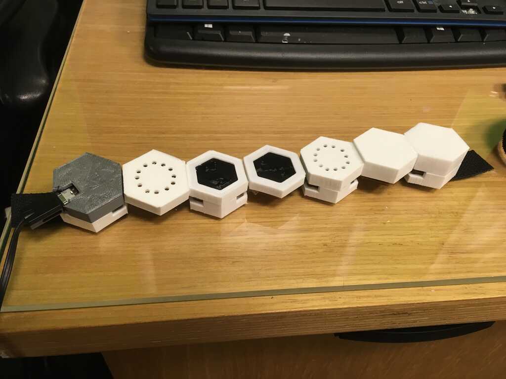
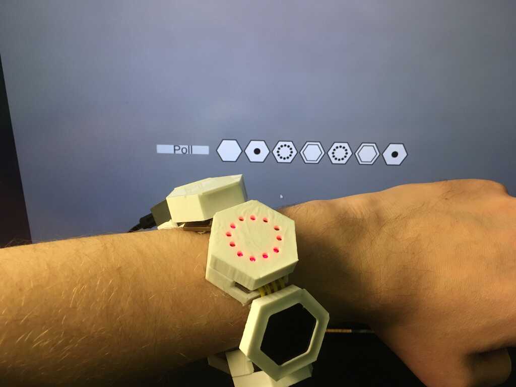
Using some double-sided velcro and hot glue, I finally got this turned into something I could wear:
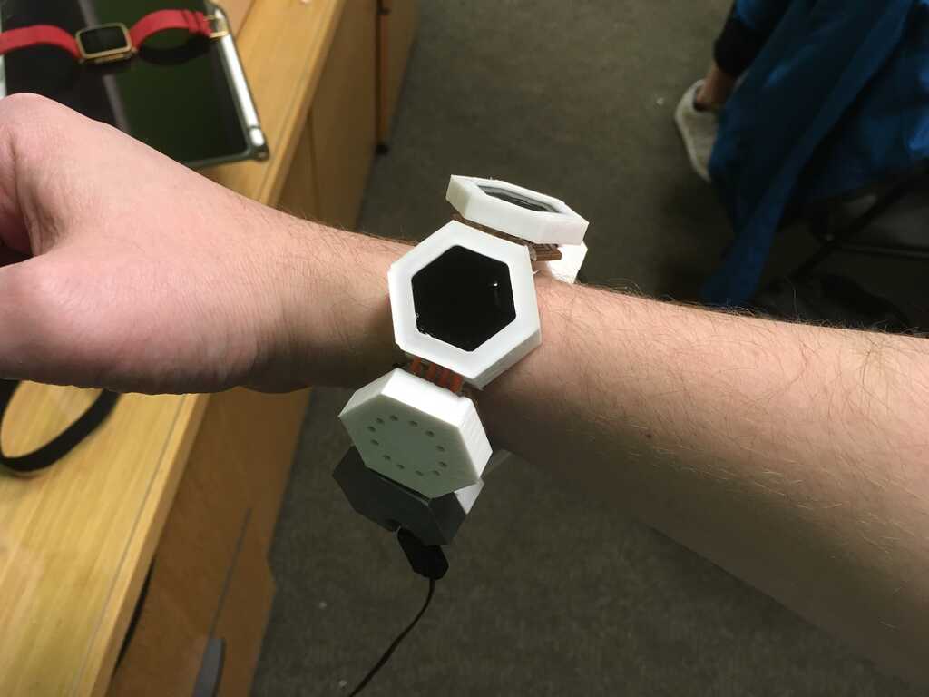
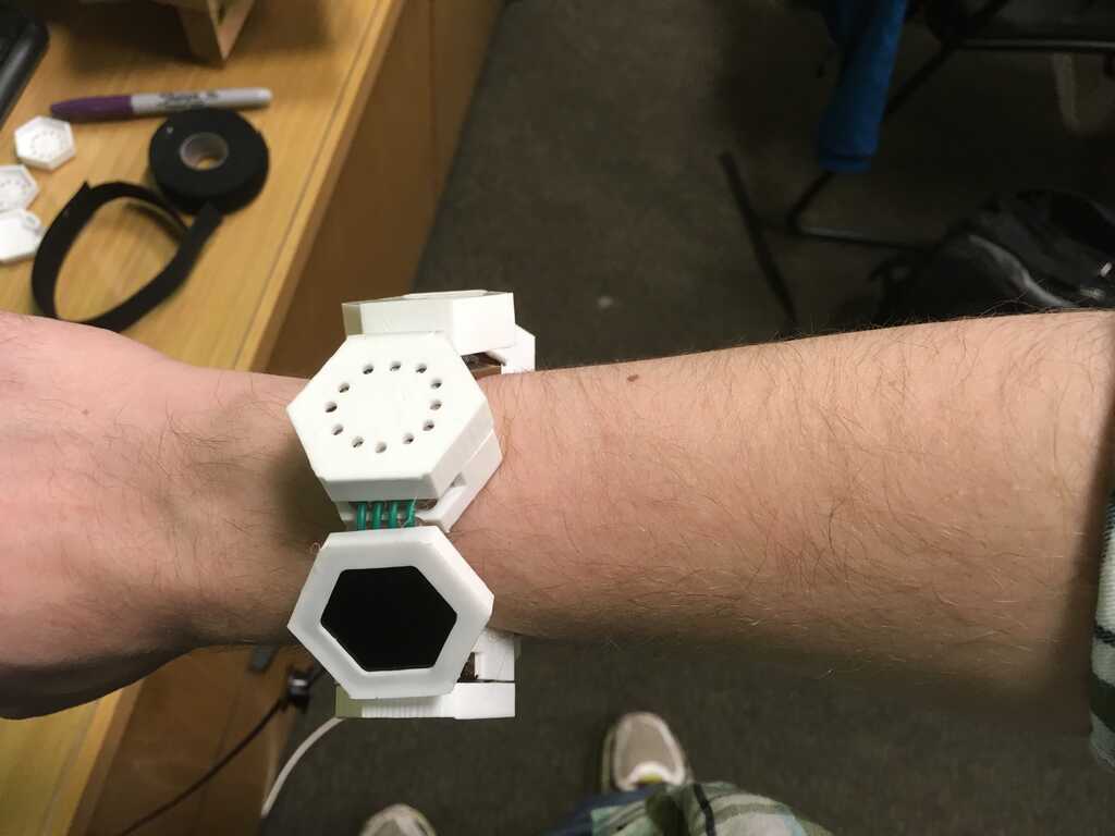
Now that I can wear it, I want to make it work.
Interfacing
I couldn't do the interface week, so I had to build an interface from scratch. I know Unity pretty well, so I figured I'd use that. The most important step would be to read Serial. Fortunately, there's a plugin that makes the whole process trivial. Using this, straight away I could poll and print out what the modules have attached to them.
From this, I started doing more. I added buttons, callbacks to send serial messages, and sprites for each of the modules. I also parsed the human-readable version of the polling message. This is the interface I had at the presentation/open house.
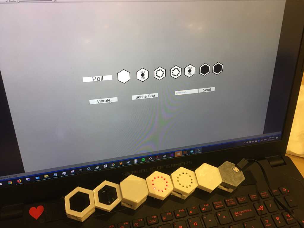
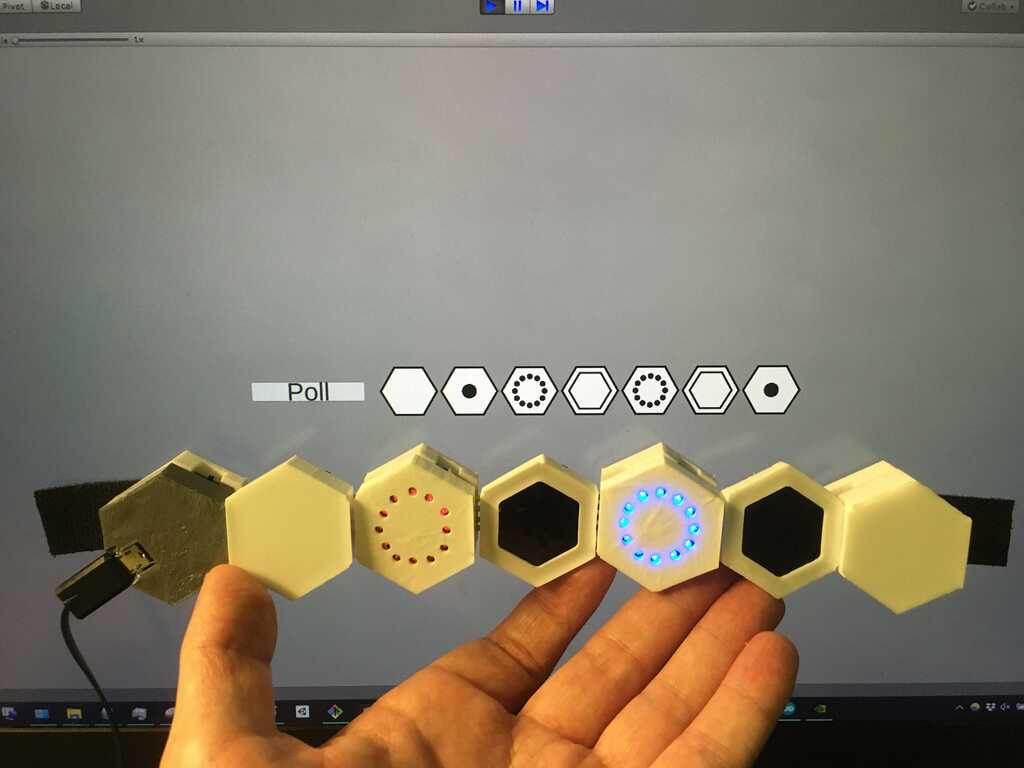
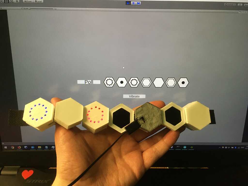
To be honest this wasn't very satisfying. Other than changing the sprites when you clicked on poll, the UI was pretty static. So I took it a bit further after the open house. At this point in time, it has different sprites for whether the vibration modules are actively vibrating, it checks for capacitive touch (if a modules is connected) every 1/10th of a second, has different sprites for that, a dropdown menu for the different display options, and intelligently hides/shows UI options depending on which modules is selected.
And here you can see them lined up better. You can also see that any module can be the master in the interface as well.
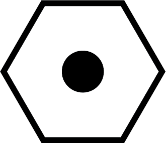
And of course, here's all of the sprites I used!


(After updating my website, I realized that one thing I should have added is automatic polling [it's a very simple implementation], but it's too late for that.)
And of course, what kind of animal would I be if I didn't leave you with a video of it working?