Week 9 - Input Devices

The Device

This week, we had to make a board with some sort of sensor on it. In line with my final project wearable, I felt that a capacitive touch array would be a necessary addition. Luckily, Matt Blackshaw had already done some work in this area, which gave me something to work off of. I also plan on adding some kind of IMU to my final project (tilting, shake to wake, etc.), but that will have to wait for another day.

The Design

The first thing I had to do was design the capacitive array. I played around with a few ideas, and ultimately decided on the first image below, based on standard capacitive arrays. The image on the right was an attempt to try and figure out something different, but I couldn't quite figure it out.

img/Week9/01A-FusionSketchUsed.jpg
img/Week9/01B-FusionSketchUnused.jpg

Once I had the sketches in Fusion (download the .dxf here), I could export them to Illustrator (download the .ai here) to generate PNG files for the vinyl cutter.

img/Week9/03A-X.png
img/Week9/03B-Y.png
img/Week9/03C-Hex.png

Using the plastic modules from last week, I was able to see what the array would look like on an actual module. I just printed the array onto paper using a normal inkjet printer, and taped it to the module.

img/Week9/02A-PrintedHex.jpg
img/Week9/02B-PrintedHexTouch.jpg

I also designed a circuit to match the standard footprint for the circuits. Because I don't yet know how I'm going to connect the modules to the slaves, I kept it as an independent module for now, with only FTDI and programming headers. The board is one-sided, but the vias are to connect the copper tape array to the rest of the circuit.

img/Week9/04A-Schematic.jpg
img/Week9/04B-Board.jpg

Vinyl Cutting

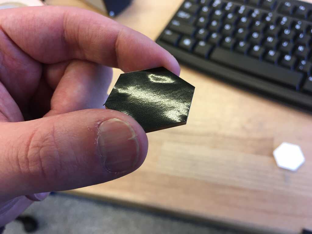
I already knew that vinyl cutting was going to be tricky for me this week. I didn't know I'd need it when I first did way back in Week 2, so I just made something neat and moved on. However, this week really needed it. So, to warm myself up, I did a test cut on vinyl with that hexagon from before. It fit perfectly on the board, so I knew I had my dimensions right! (Whoops, spoiler, I already milled my board)

img/Week9/05A-TestCut.jpg
img/Week9/05B-TestOnBoard.jpg

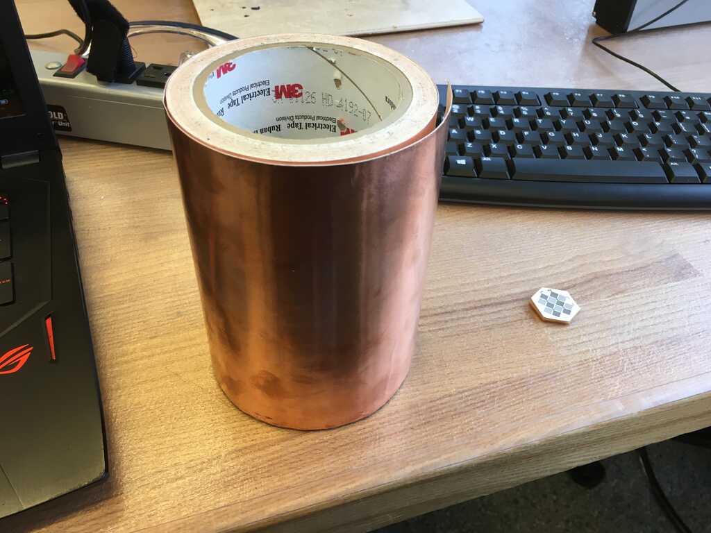
Now, the array needed a conductive material with an adhesive layer, so what better material than copper tape?

img/Week9/06-CopperTape.jpg

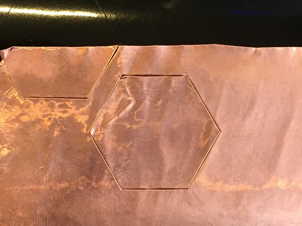
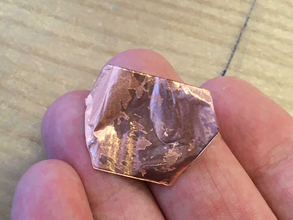
The first thing I tried was to directly adhere the copper tape to the vinyl and cut it from there. I cut it out with 80g of force at 2cm/s, but that didn't quite cut through the vinyl like I had wanted. However, it went much smoother than I had expected. (This was due to both the simple nature of the cut I was making, as well as the strong adhesion to the vinyl.)

img/Week9/07A-CopperCut.jpg
img/Week9/07B-CopperPeel.jpg

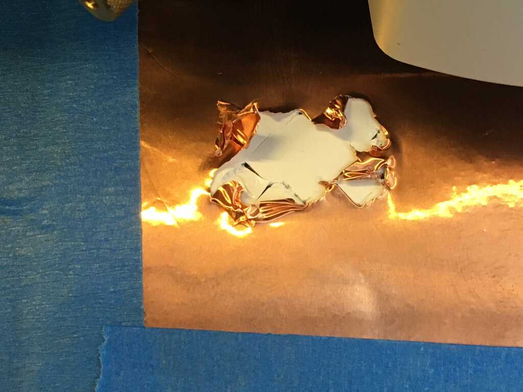
To get through the vinyl, I tried just a little more force at 100g. Other than setting my origin incorrectly, I cut exactly what I wanted! Looking at the actual tape, on the other hand, adhering it to the vinyl and then removing it took off a ton of adhesive, as you might be able to see in the second picture.

img/Week9/08A-CopperCutPeel.jpg
img/Week9/08B-CopperNoAdhesive.jpg

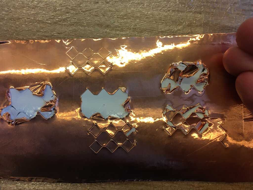
Alright, now it's time for a new approach. This time, I left the copper tape on its original backing, and taped down all of the sides with masking tape. Since I wasn't convinced that this was going to scale down to my tinier features, I jumped right in and started cutting those out instead. I tried a large variety of forces, and reduced the speed, but I just couldn't get good results. (I believe this was due to the weak adhesion of the copper tape to the original backing, leading to the knife dragging the tape behind it.)

img/Week9/09A-MaskingTapeAttempt1.jpg
img/Week9/09B-MaskingTapeAttemptMany.jpg

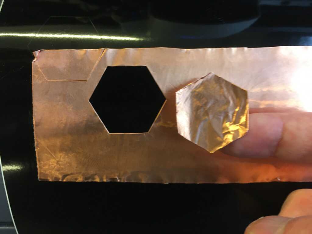
Frustrated, I looked at previous years' students' work. While I'm not exactly sure what Honghao Deng did, it put me on the right track. First, I peeled the copper tape. Next, I adhered the copper tape to the non-sticky side of some transfer tape. Finally, I adhered another piece of transfer tape on top of the back sides of the other two, making a transfer tape/copper tape sandwich, with all of the adhesive sides facing the same direction. I then adhered that sandwich to the vinyl roll.

img/Week9/10-TransferTape.jpg

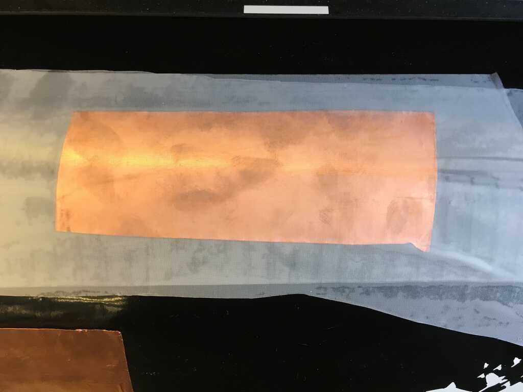
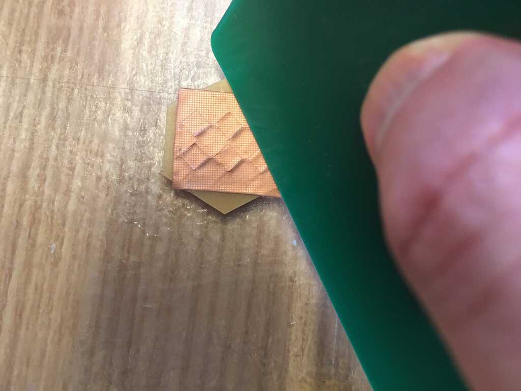
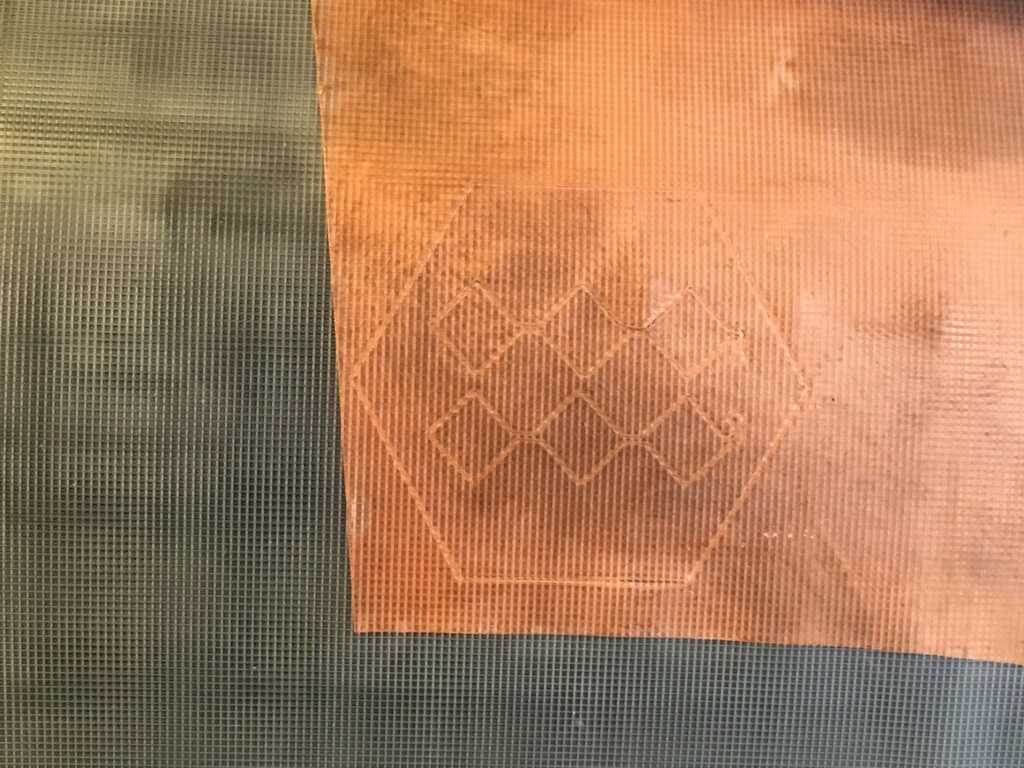
Since I was going to be cutting through so many layers, I tried 100g and 1cm/s at first, but that cut through all 3 layers. Lowering it to 80g, I seemed to get what I wanted! Once I cut it out, I cut around the rows with scissors. I peeled off the bottom layer, and smoothed it onto the hexagon module using a plastic card.

img/Week9/11A-SquareOnHex.jpg
img/Week9/11B-PlasticCardSmoothing.jpg

When I went to peel it, I unfortunately discovered that the vinyl cutter hadn't gone all the way through.

img/Week9/12-PlaceFail.jpg

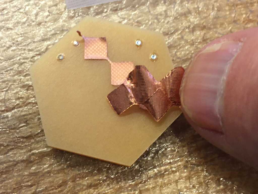
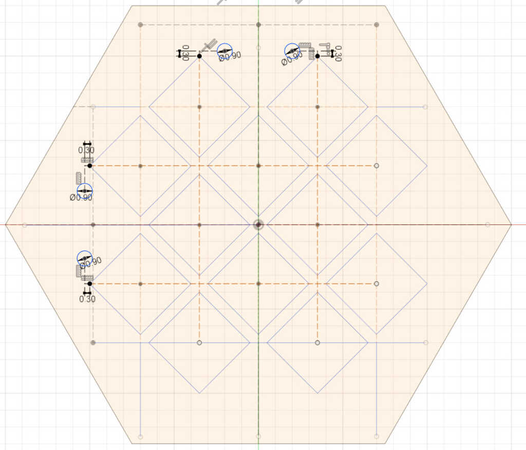
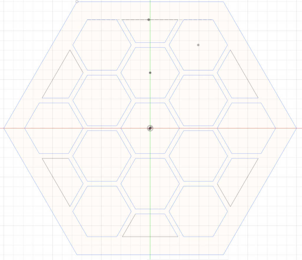
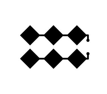
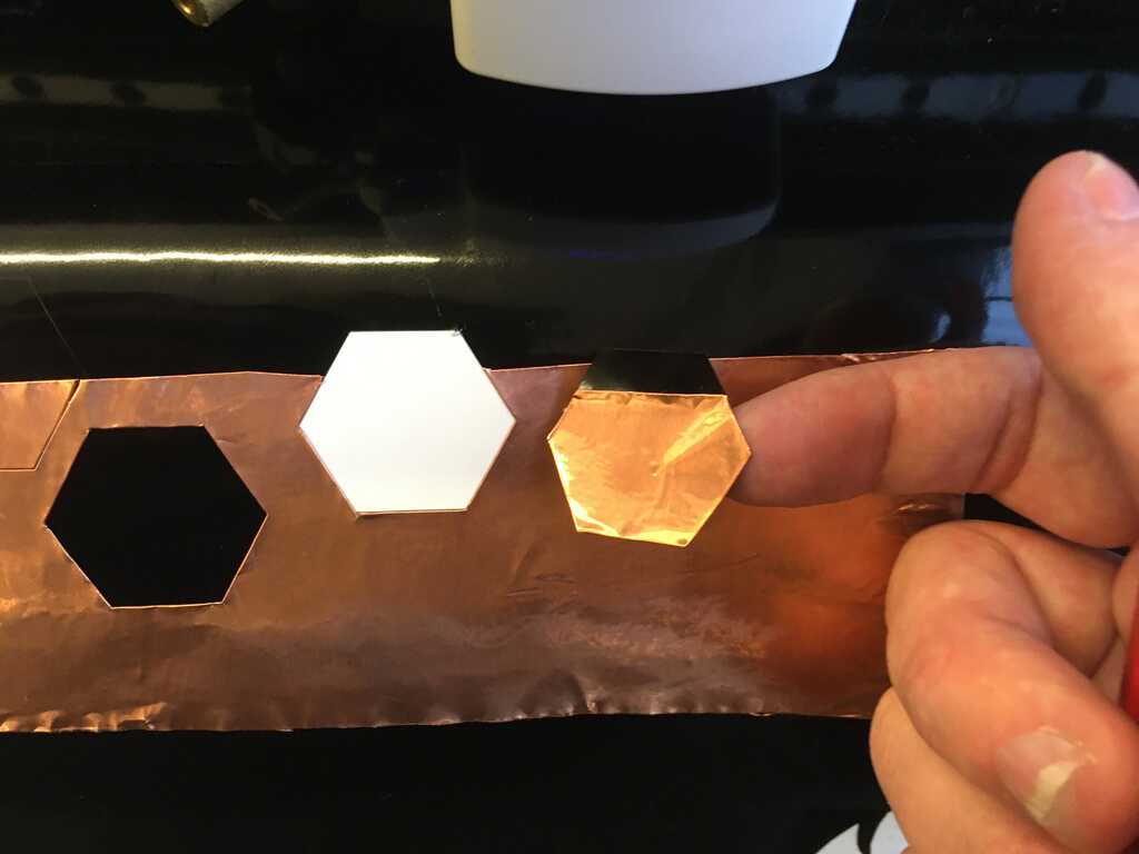
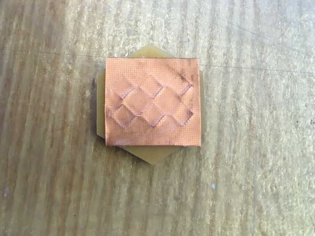
Not cutting through wasn't my only problem, I also had a hard time placing the square exactly right on the hexagon! Fortunately, when I exported the images from Illustrator, I gave them all the same dimensions, so if you stacked them on top of each other, they'd perfectly match up. So that meant that I could cut out a set of rows, and then cut out a hexagon on the same origin, and it would match up exactly. The other, major issue was not cutting all the way through. What I ultimately discovered was that two passes at 40g and 1cm/s gave me exactly what I was looking for.

img/Week9/13-HexagonCut.jpg

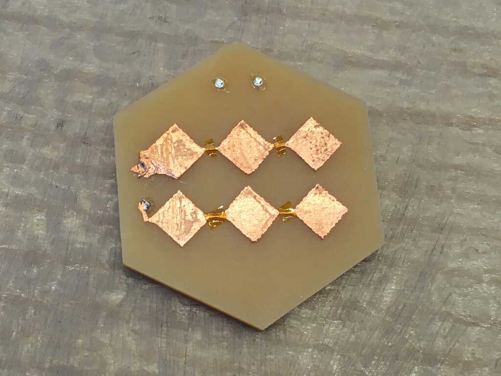
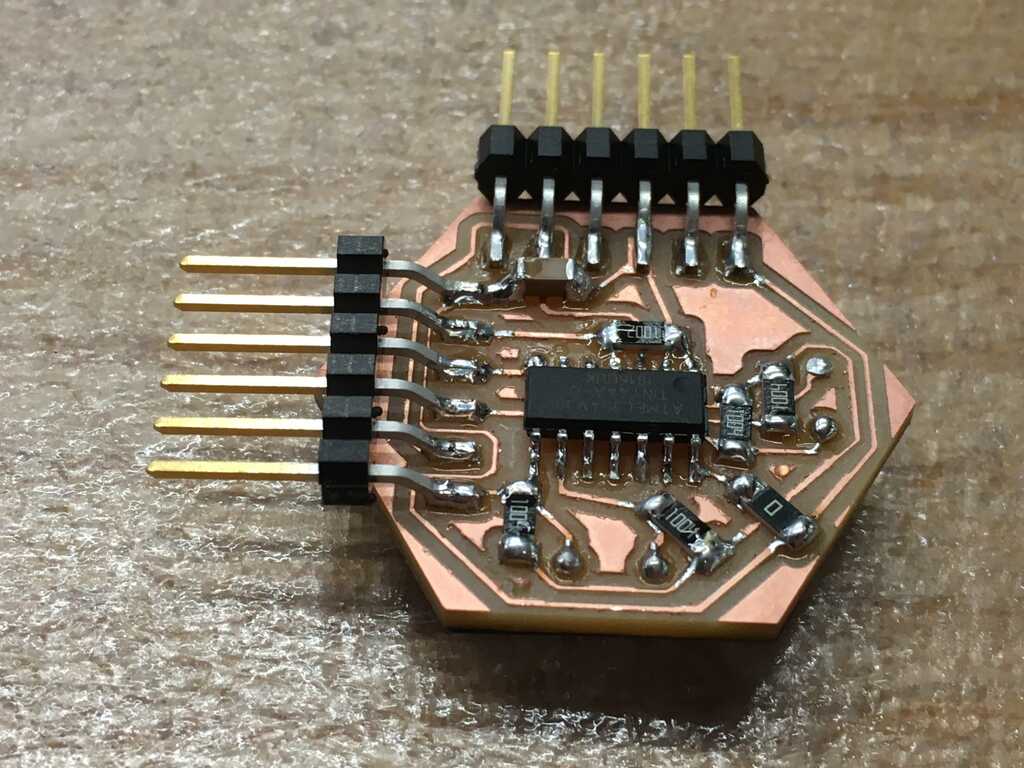
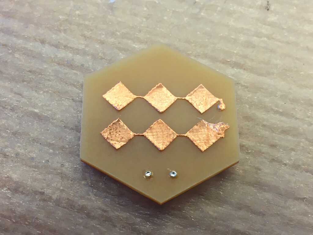
With a good cut, I was able to easily place and peel. I double checked my connections, and I wasn't getting any connection between the two rows and the other side of the board. There was already solder in the rivets, but that was placed before the copper tape. I then went and flowed a bit more solder through the rivets, and briefly touched the iron to the tape contacts to secure a connection. It worked beautifully.

img/Week9/14-PlaceSuccess.jpg

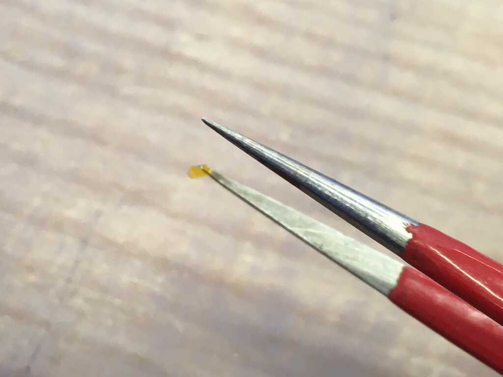
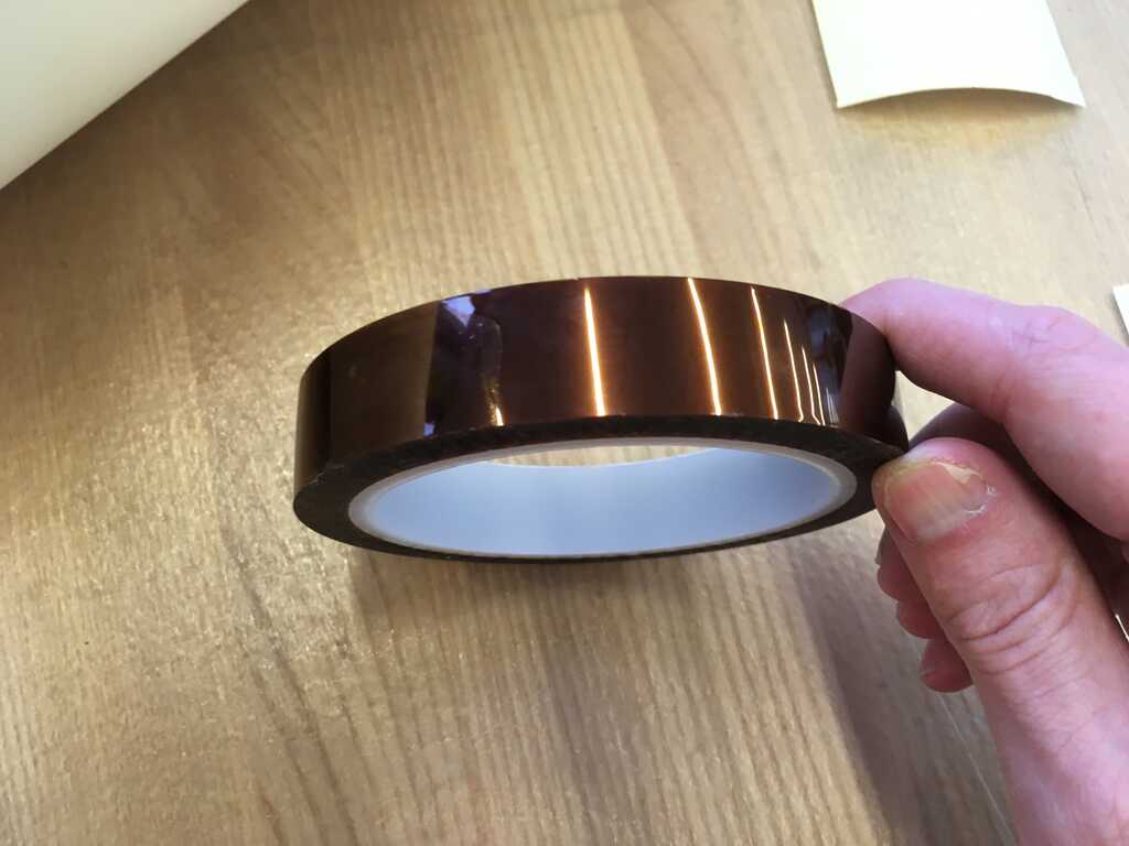
Now, the next part isn't as easy as slapping the other rows onto the board. I have to make sure the two layers are insulated from each other. Otherwise, I'd essentially just have a large chunk of copper on one side of the board. To get that insulation, I used Kapton tape. It can apparently withstand high temperatures, but I'm not using it to its full potential here.

img/Week9/15-KaptonTape.jpg

Taking very tiny pieces, I placed them over the junctions of the rows. I had to use two tweezers to manipulate these miniscule chunks.

img/Week9/16A-TinyKapton.jpg
img/Week9/16B-AllTapedUp.jpg

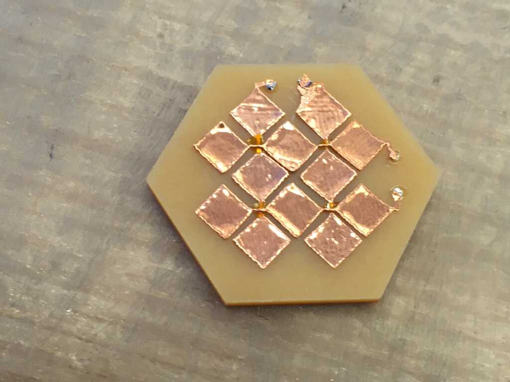
The second set of rows went on even smoother! Slightly misaligned (my fault), but there weren't any shorts and a bit of solder connected everything back, so no problem at all.

img/Week9/17-SecondSetApplied.jpg

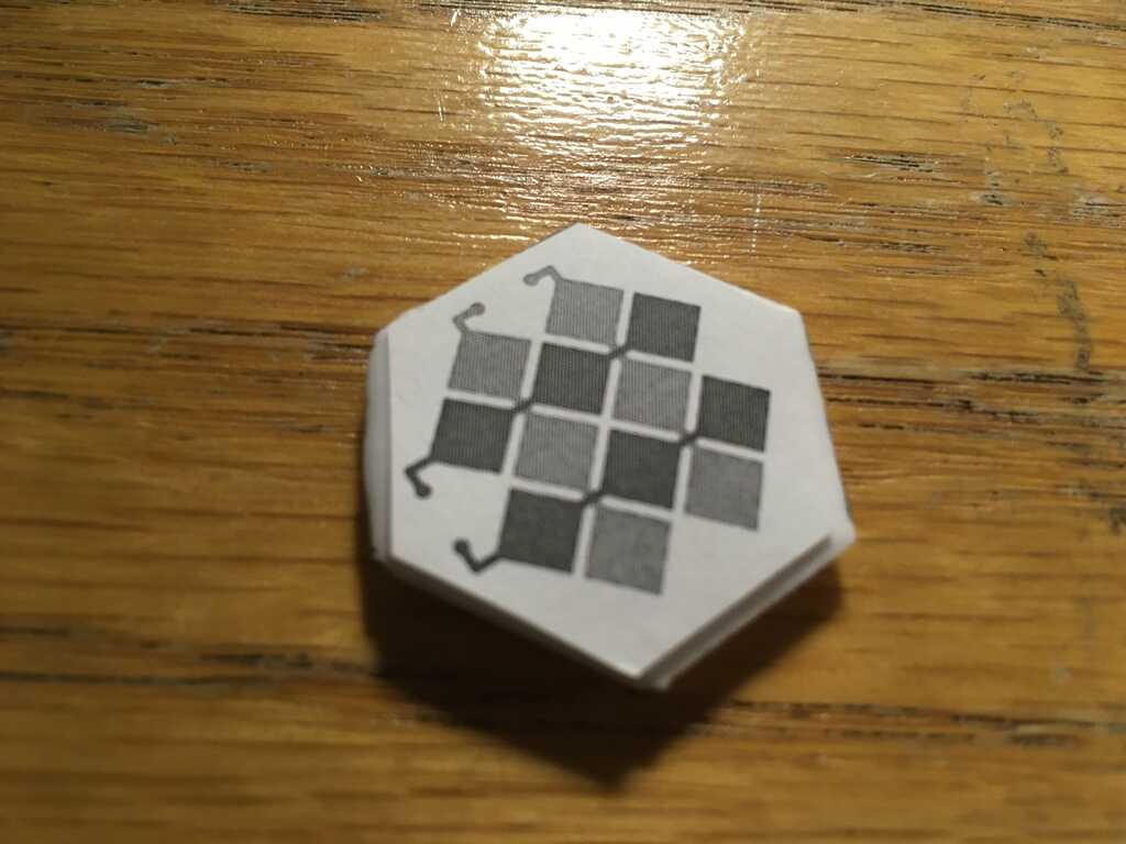
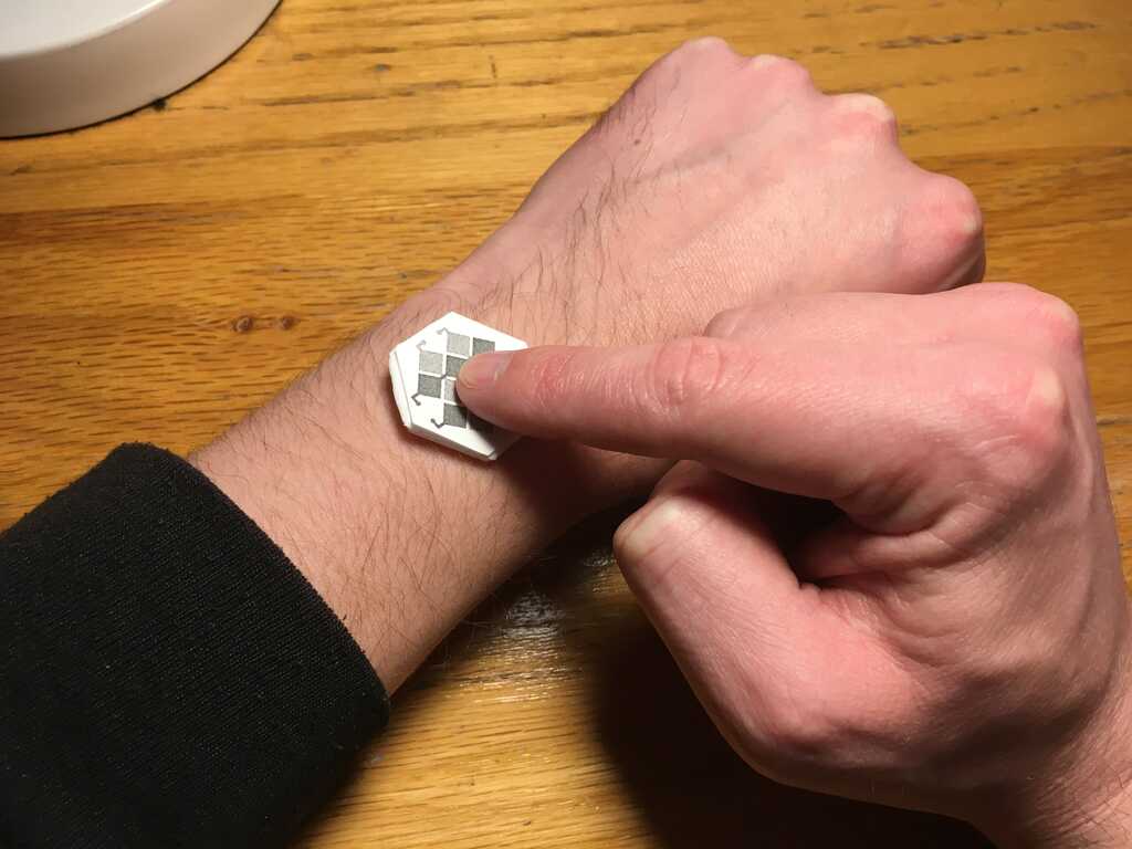
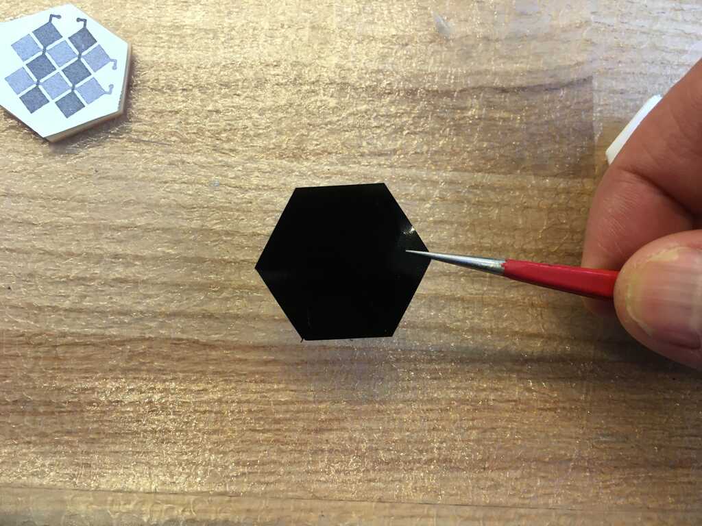
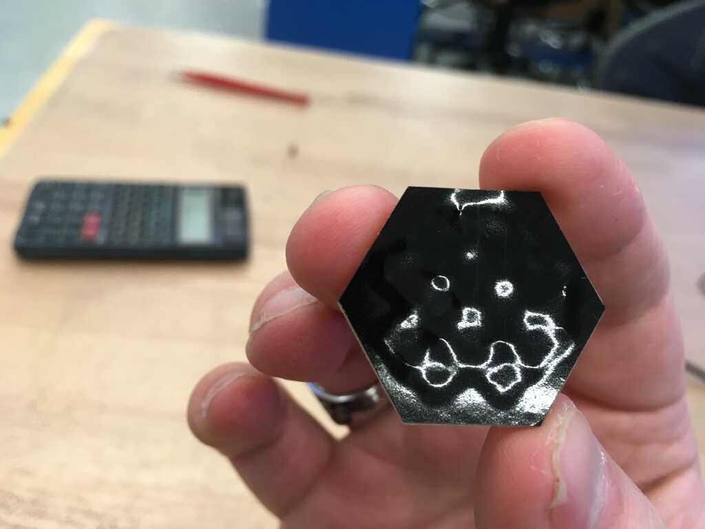
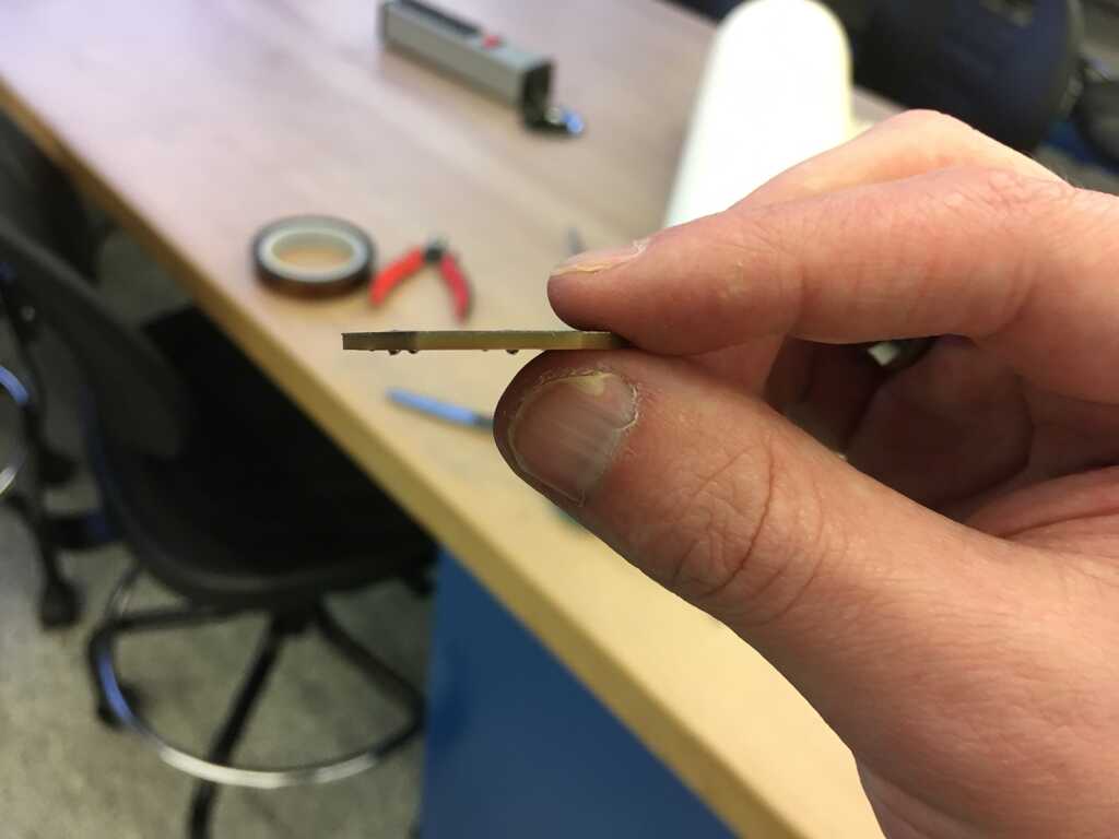
To top everything off and give it a smooth finish, I cut out another hexagon out of vinyl and slid it on. Check out how thin the actual capacitive layer is!

img/Week9/18A-VinylApplied.jpg
img/Week9/18B-SuchThinFormFactor.jpg

Circuits and Coding

Stuffing the circuit was no problem. Slap some components on the board and everything is peachy. The only pitfall I had here was the FTDI VCC pin wasn't properly soldered to this new board.

img/Week9/19-Stuffed.jpg

Remember that I unfolded the standard 2x3 header into a 1x6 header? I had to take some header wires, stick them into the ICE, and plug them into the correct pins. It took some critical thinking, but luckily I had laid out the pins in a similar pattern.

img/Week9/20-ICEAdapter.jpg

With all the wiring set up, I was ready to code. Matt's code was very readable and easy to understand, so I just modified it to match the circuit I had designed (fewer pins, some debug serial lines). I got it printing out through Arduino's serial monitor just fine.

img/Week9/21-SerialValues.jpg

One of the biggest changes I added was an auto-calibration feature, which ended up being my downfall. What it does is it will wait ~20 cycles, and then create thresholds based off of an idle value. Ideally, this would give the values a bit of time to settle. For one of the rows, row 1, this worked perfectly. Touching the vinyl anywhere along that row would yield a touch. The rest, not so much. This was the only one not attached to a multi-function pin, go figure. Here's the data for all of them, with the y-axis representing values from the ADC. (download the .xlsx here)

img/Week9/22-AllData.jpg

And here is the data broken up. The dotted lines represent the auto-calibrated thresholds. As you can see, the first row works perfectly fine. The other 3, the threshold is set really low, but the values stay generally much higher than that.

img/Week9/23-IndividualData.jpg

The troublesome rows all connected to different pins on the programming header. Even though the pins weren't connected to anything, I had a sneaking suspicion that they were to blame. I felt like the calibration was calibrating to their capacitances since the pins were large compared to the copper tape. Touching the pins would indeed cause the read value to cross the threshold.

img/Week9/24-Hypothesis.jpg

The only way to remedy that, however, would be to completely remove the pins from the board. This meant that I wouldn't be able to program it again, so I uploaded one last program (similar to Matt's original, just sent data when pins were pressed and released), and went at it. Unfortunately, I tore off a bunch of traces, which meant I really couldn't program it anymore. (But you still can! download the .zip here)

img/Week9/25-Whoops.jpg

I gave it a hail Mary, plugged it in, and...

Yup, it didn't work. Touching the traces for the faulty rows worked, but I just wasn't getting it on the back.

Conclusion

After screwing the board up, I had a couple options: 1. restart and do everything again, or 2. accept what I lost, and move on with what I learned. I started doing #1, by creating a new circuit (which doesn't share any pins for the capacitive inputs), and modifying the code I would upload. I ended up deciding that I would stick with #2, because the next iteration of my circuit is better off being built within the constraints of my final system. I know now that I can make a capacitive circuit, and fit it into the form factor of one of the modules. I still need to figure out how to use I2C (can't wait for networking week!), and I need to decide on how to physically connect the modules to the slaves (which will greatly influence hardware design).

Bonus Website Updates

This week I also updated my website compiler to allow me to add images in just one line, as well as simplifying the code for headings. I also added the ability to create and recall variables. At the end of the semester, I'll post that source code to the website somewhere.

This website was created by Harrison Allen for How to Make (Almost) Anything at MIT in 2019