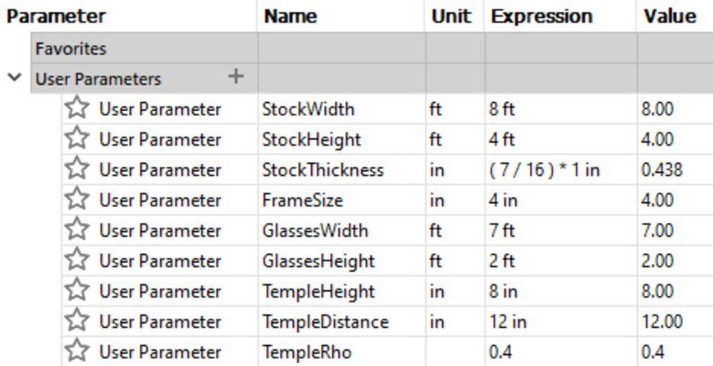
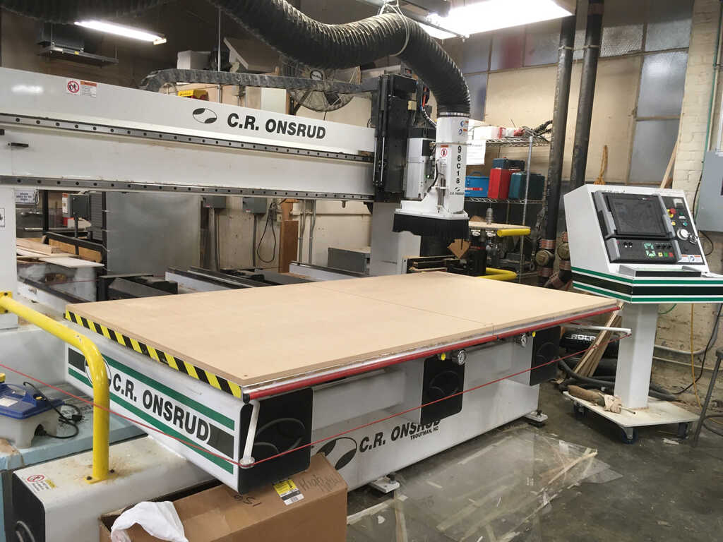
The EDS for EECS students doesn't have a large enough machine for us to cut out our 4'×8' board, so we had to use the Architecture shop in building N51. Because of this, some of us had to design and cut our pieces early. In my case, I had already completed my glasses before last week's lecture. It served as a guinea pig to figure out what exactly needed to be done to double check everyone else's jobs going forward. Here are some things that needed to be done on the software side to get this rolling:
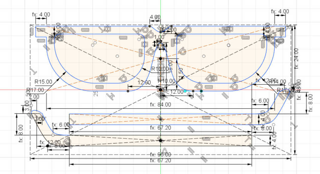
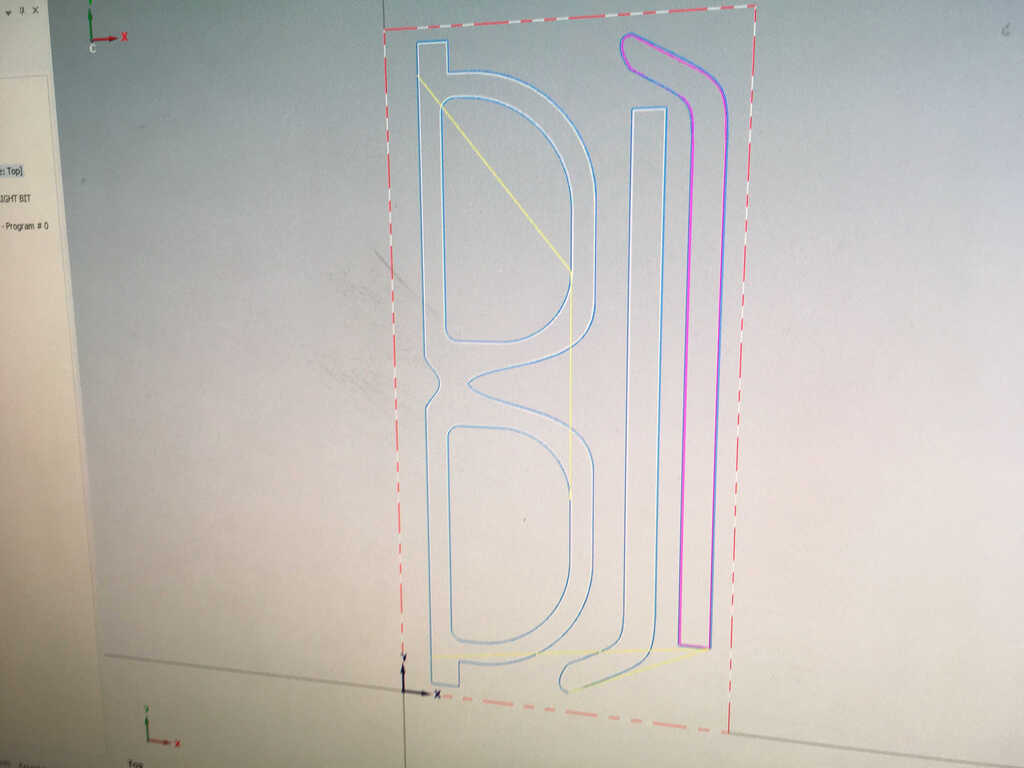
- Export the sketch into a .dxf format. Here's what I exported:
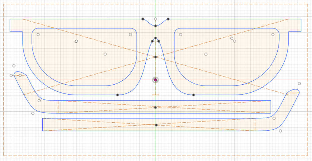
I removed a bunch of construction lines, but we weren't sure how many we'd need to remove overall. As it turns out, it would have been most beneficial to remove every single one because each construction line counts as somewhere you want to cut in MasterCam. We ended up doing that later anyways.
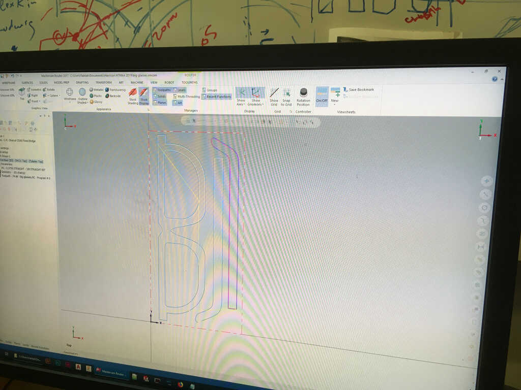
- Open up the file in MasterCam, and define the toolpaths. I don't have the libraries, but the Architecture department has their own tool libraries for the specific machine in their shop. Anthony helped me with the first part of this, and we met with Jen to go over all of the toolpaths and get the right libraries and everything. Here's what MasterCam (sort of) looks like:
There are some things that can be wrong we had to fix:
- Removing all of the construction lines manually in MasterCam
- Making sure the tools for each job were not ordered sequentially. The machine has a bunch of different tools that it picks from, and they're all in a specific order. This means that to use the right endmill, you have to make sure the correct number is assigned in MasterCam. Luckily for me, since I only needed one, and it happened to be the #1, I didn't have any issues. But for others, this was definitely a problem.
- The stock origin needs to be defined at the origin properly
- Sometimes the paths will cut on the wrong side. This can either be on the inside of an outer cut, or the outside of an inner cut. This can be resolved by either reversing the path, or switching the side it's on.
- The machine belongs to this series, and I'm pretty sure it's a 96C which isn't listed on the Onsrud website.
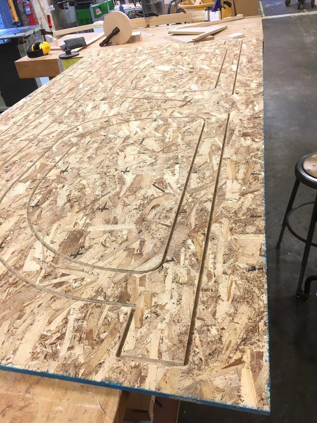
It uses vacuums to hold down the part, so we can't cut all of the way through. Instead, we use what's called an "Onion Skin", which leaves a very thin strip of material on the bottom to maintain suction and prevent the piece from becoming loose. We had to adjust the cut depth to allow for this.
- If running many parts or multiple jobs, it's best practice to minimize the space that the parts consume on the board, playing a tricky game of Tetris. However, there was only one other person ready at the time, and none of her parts fit on the same piece, so we ultimately decided to just scrap the remaining OSB. Later, I decided that the lenses could be salvaged since they had a large chunk of OSB real estate. On a more valuable material, e.g. better wood or metals, then you would absolutely want to squeeze every last drop out of the stock.
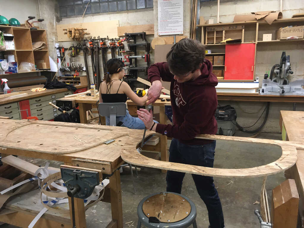
After all of this was complete, I took my MasterCam file to the Architecture shop and Jung helped me double check everything. Cutting on the machine itself was fairly straight forward.
- Run a warmup process (it basically spins the heck out of the spindle)
- Place the stock on the machine bed
- Turn on the vacuums
- Load up the cut piece .nc file
- Run the process
When we ran it, we had a couple issues:
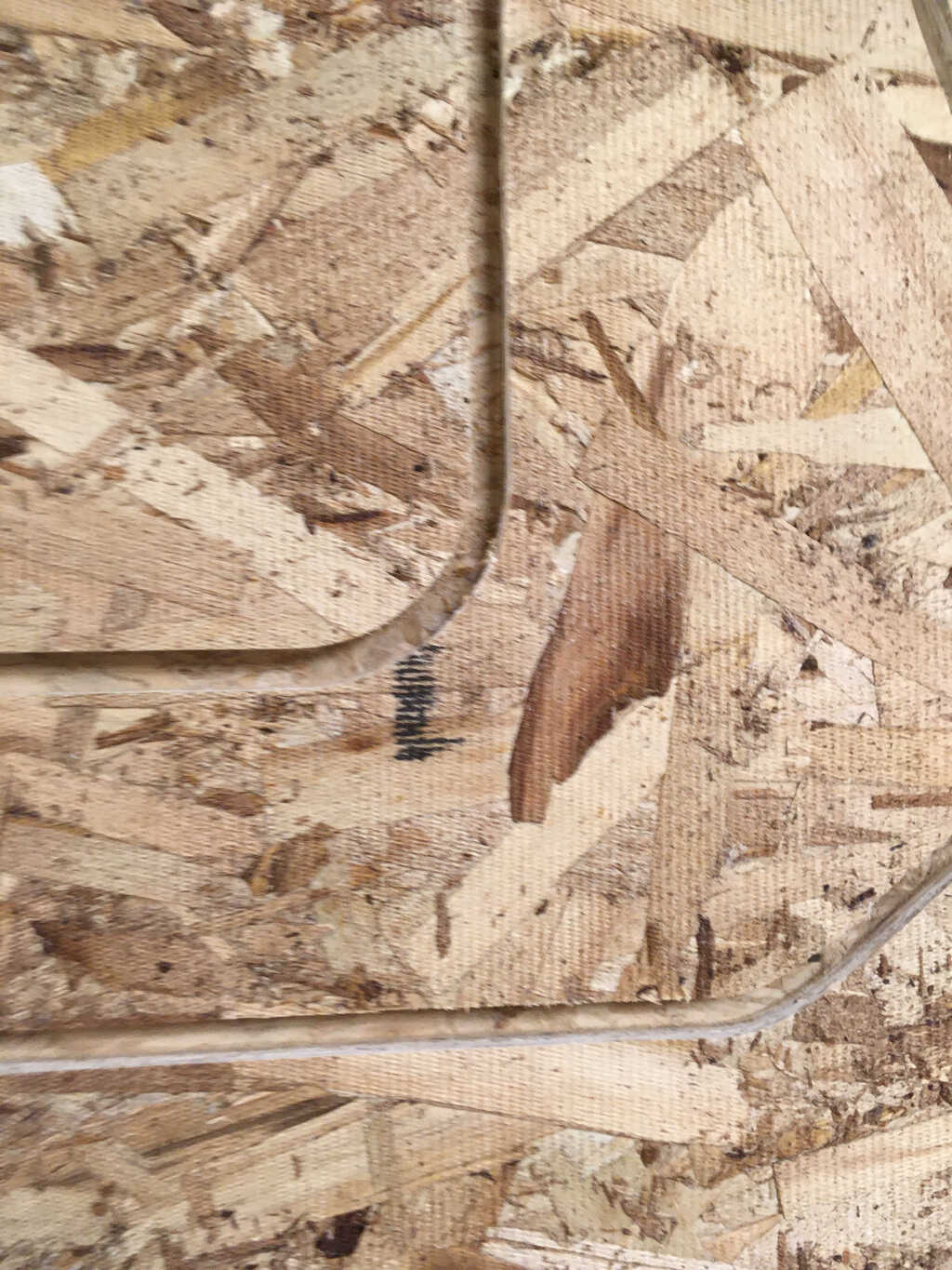
- There was an errant path left over that just meant the tool ran over the same line twice, which just wasted time, but could have been bad.
- The onion skin didn't cut as thin as we expected, so we tried running it again even thinner. It seemed like the endmill just wasn't properly aligned on the z axis.
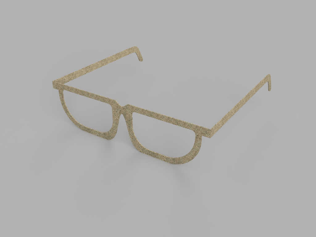
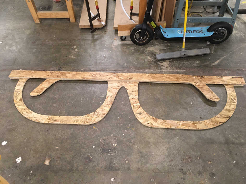
In the end, the cut came out well!
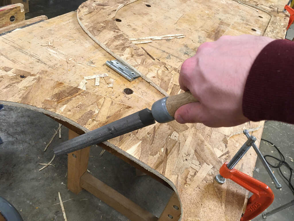
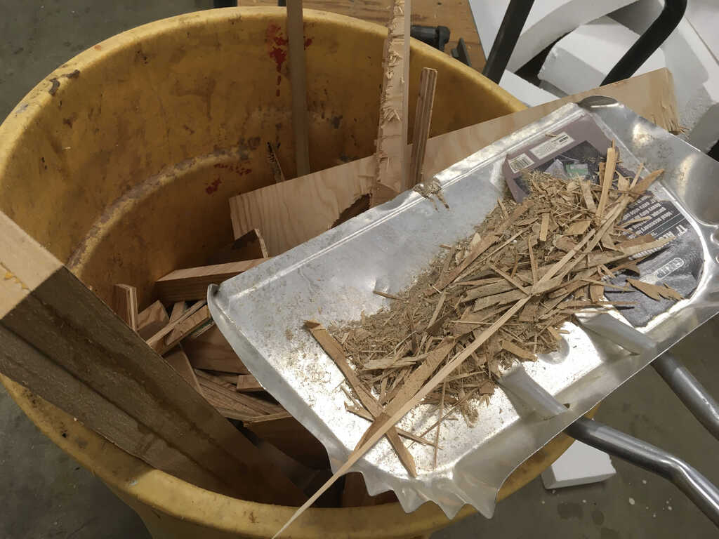
I couldn't just snap off the onion skin, so I used a utility knife to cut out the onion skin.
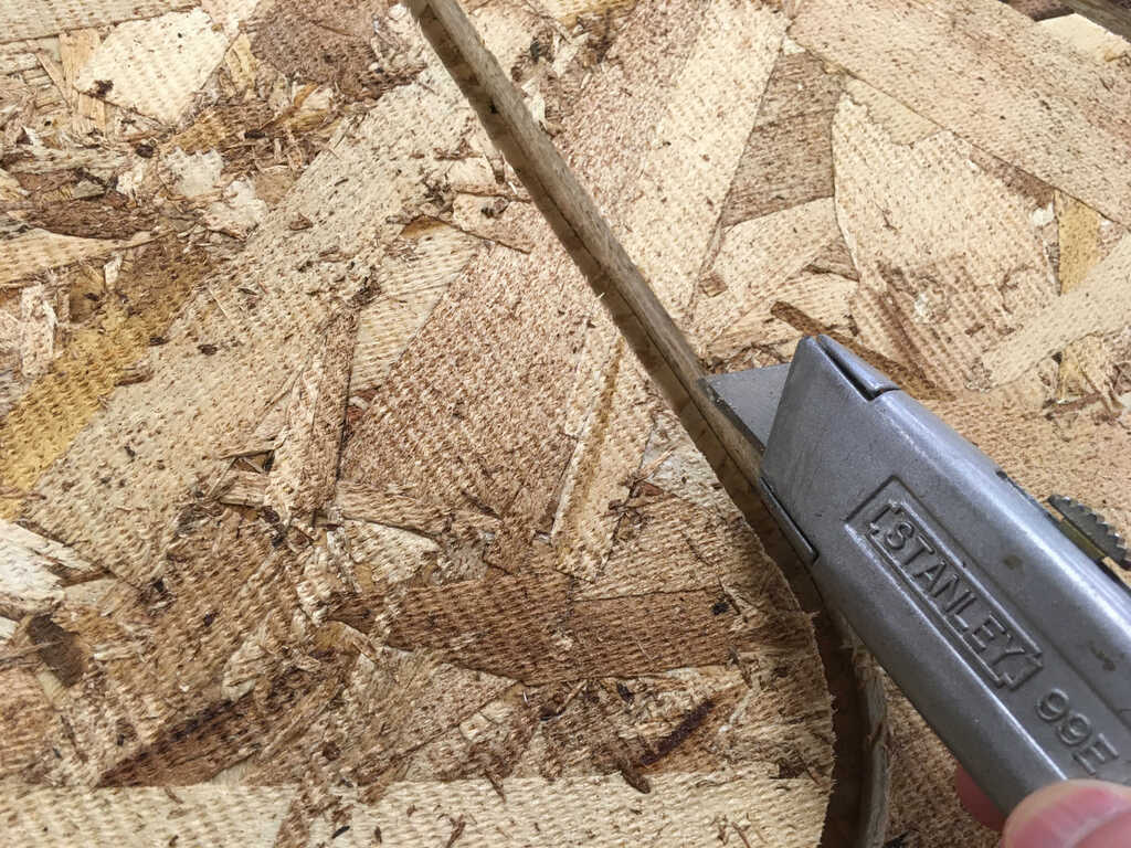
It left a bit of skin attached to the side I didn't cut, which was fine, except when I'd cut on the wrong side. Then I'd have to cut it all again.
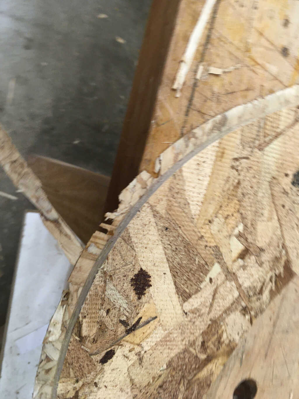
To smooth things down, I used a wood file. (s/o to Premila for the photoshoot)
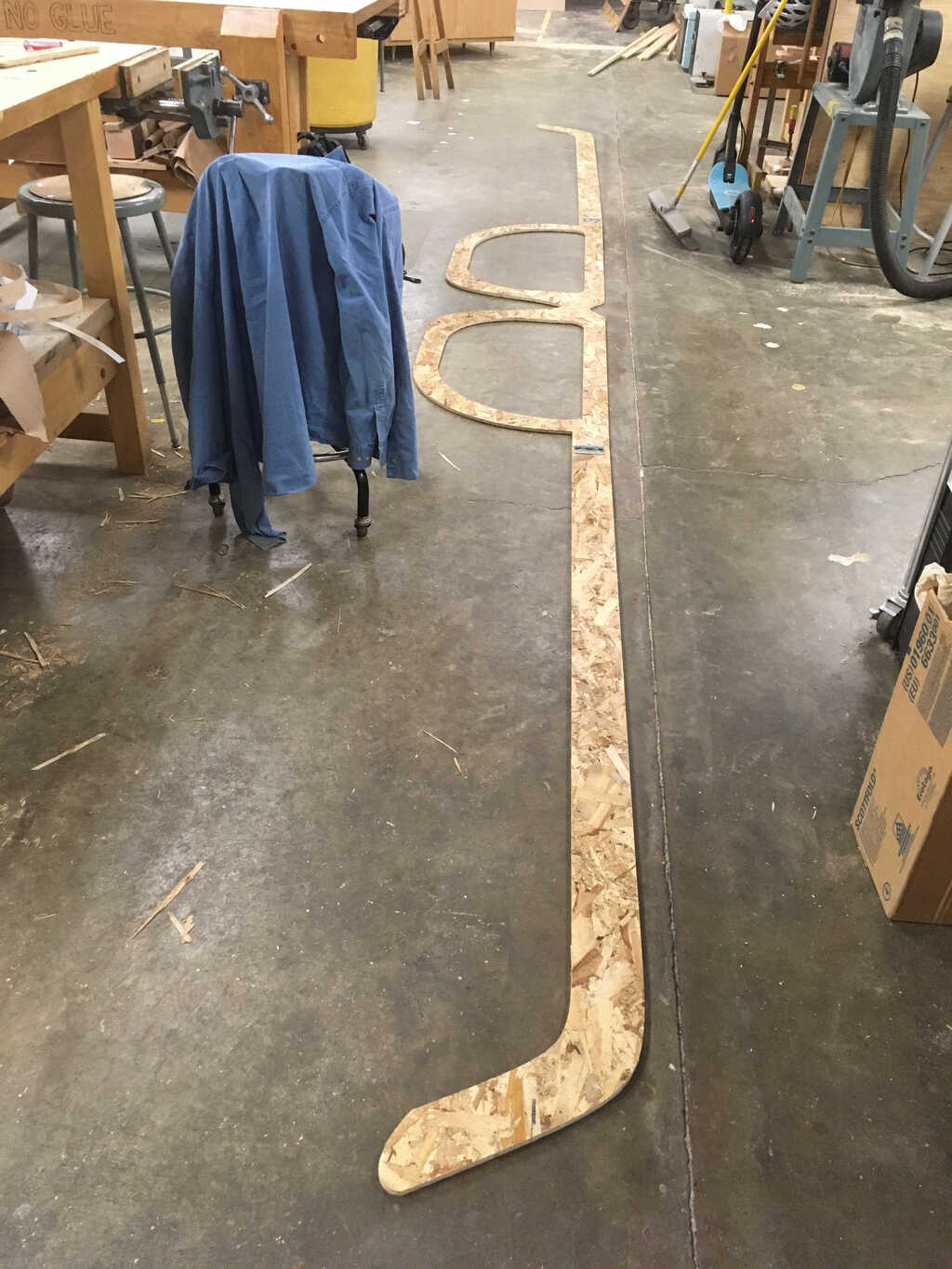
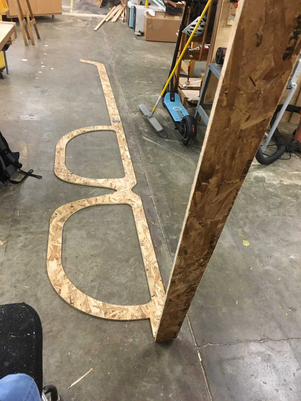
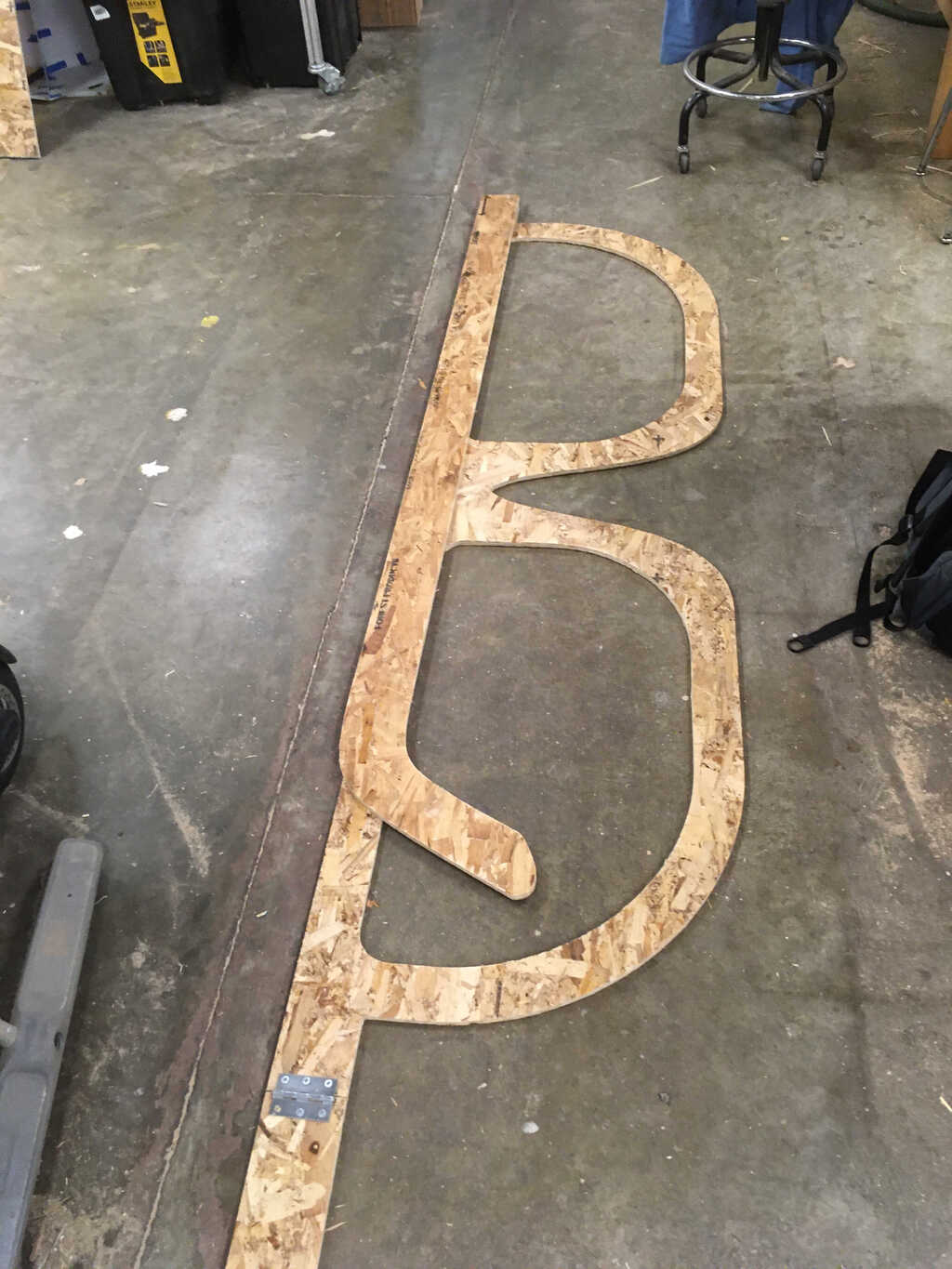
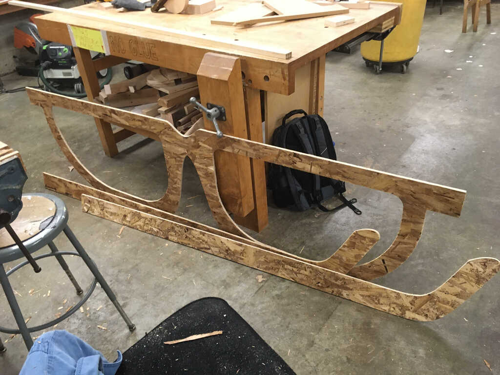
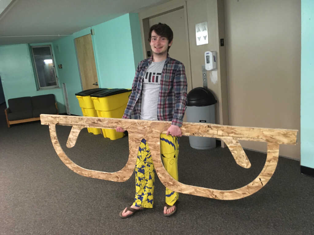
Look at it, all cut out!
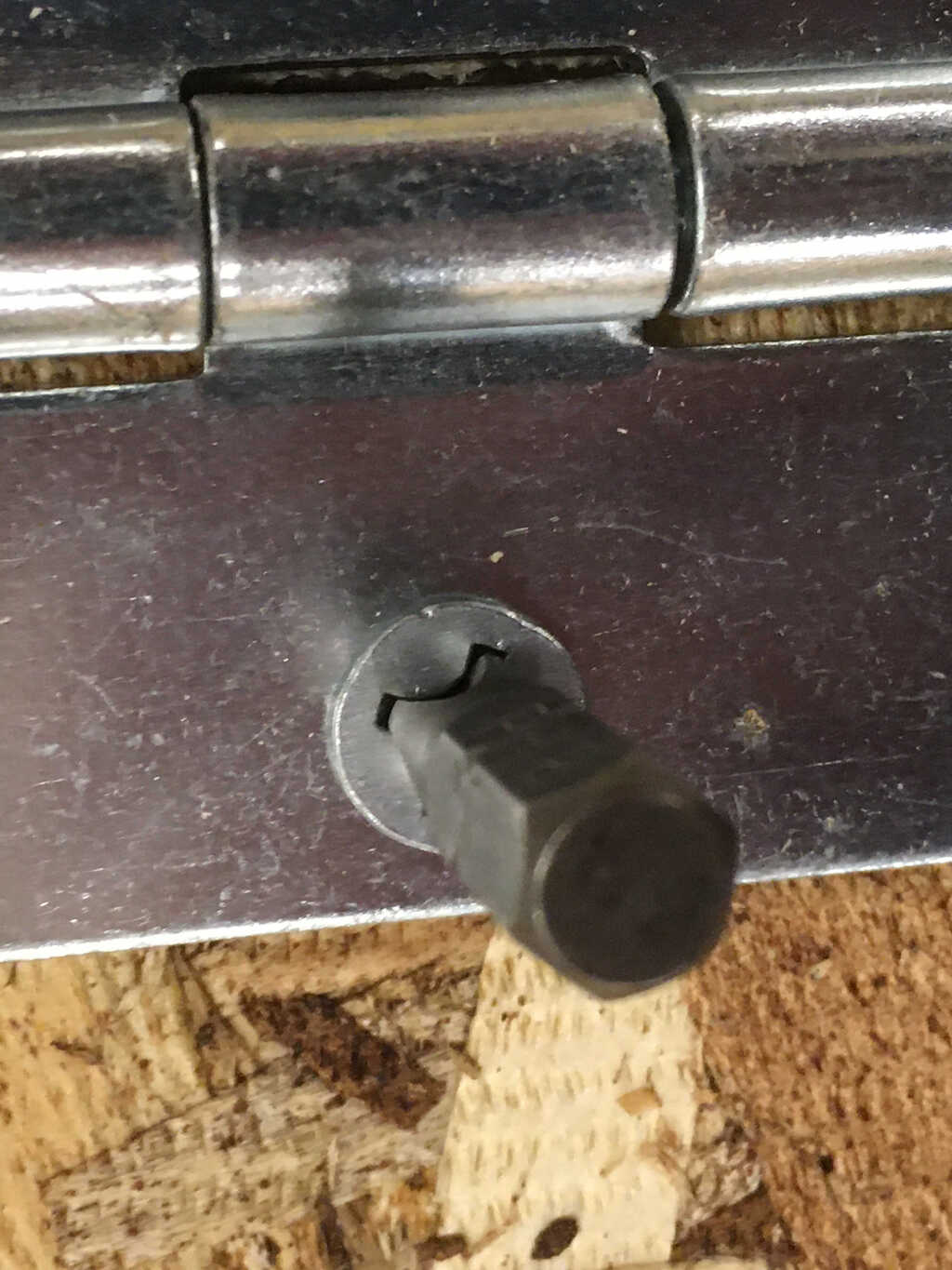
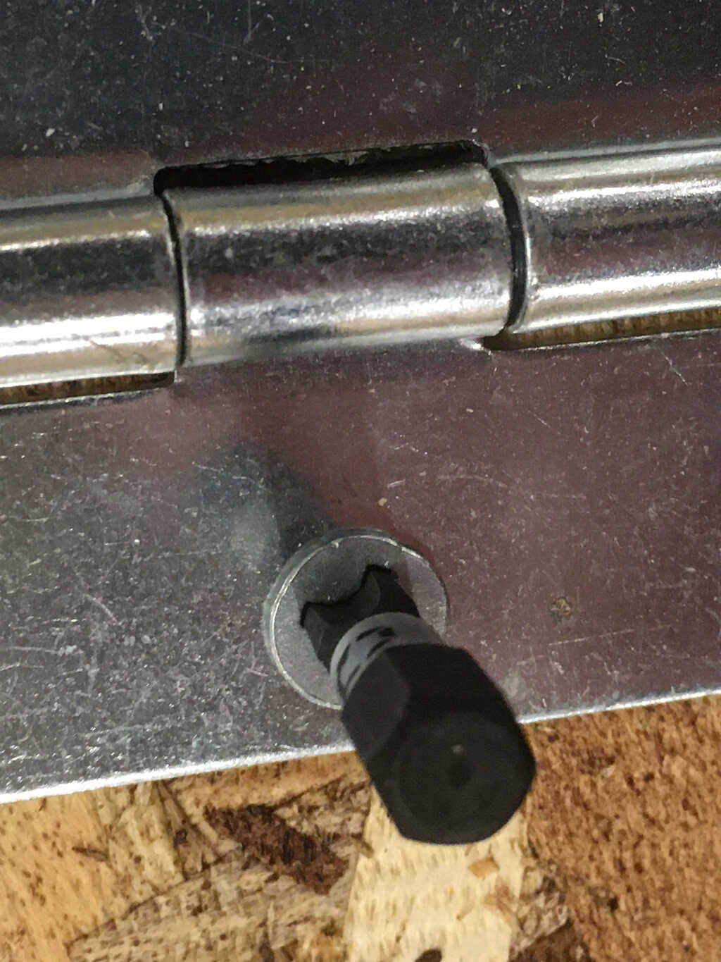
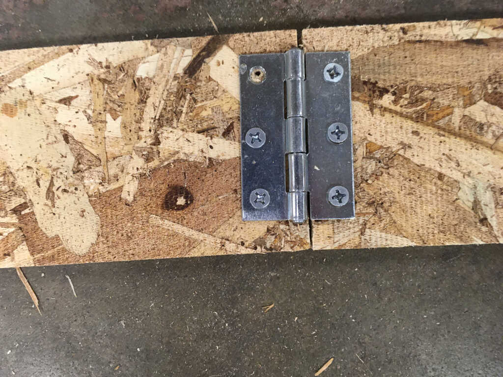
I wanted these to move like actual glasses, so I found some hinges and wood screws haniging out in a supply drawer. Using a power drill, I secured the legs to the frame.
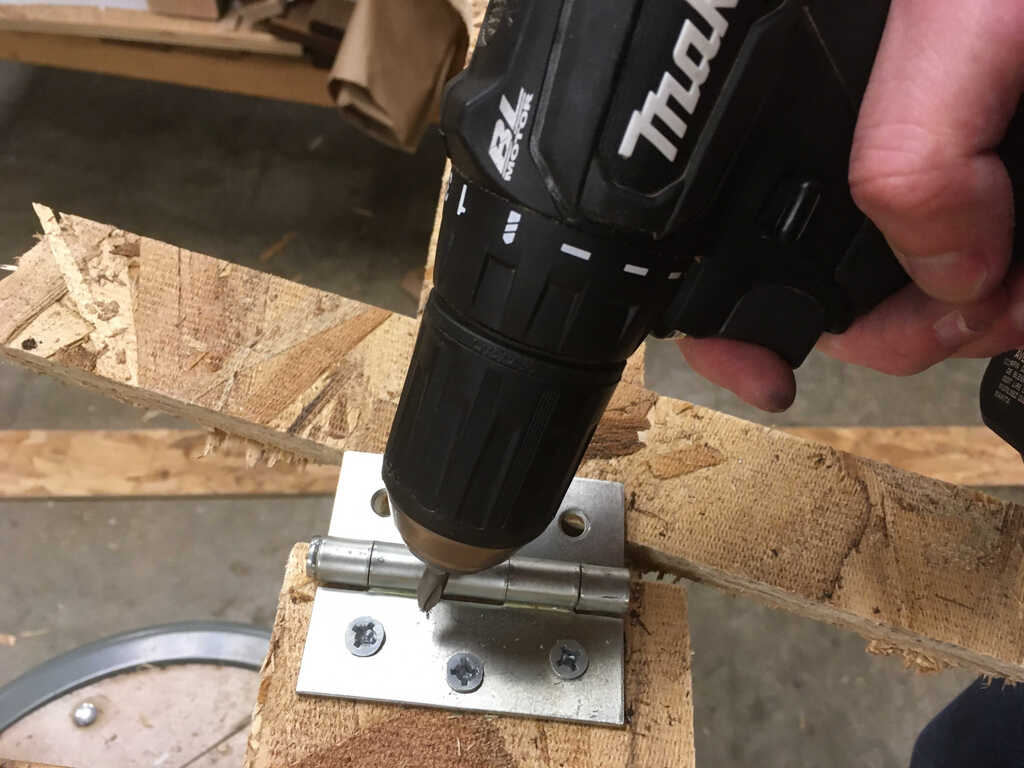
I had a hard time screwing everything in, as the largest drill bit I could find was slightly too small. This led to some stripping of screws (as you'll see in a bit). Luckily, I was eventually able to find one juuust large enough for a snug fit.
I only had 10 screws, so I couldn't perfectly secure the hinges. In this closeup, you can see some stripped screws (oops), and an empty hole where the screw wasn't properly aligned, and I couldn't get another one in its place.
Let's see how these hinges work:
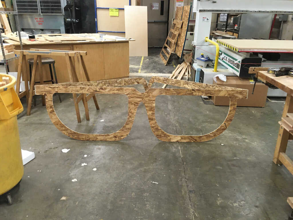
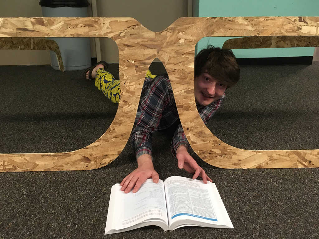
Did I mention these glasses are huge??
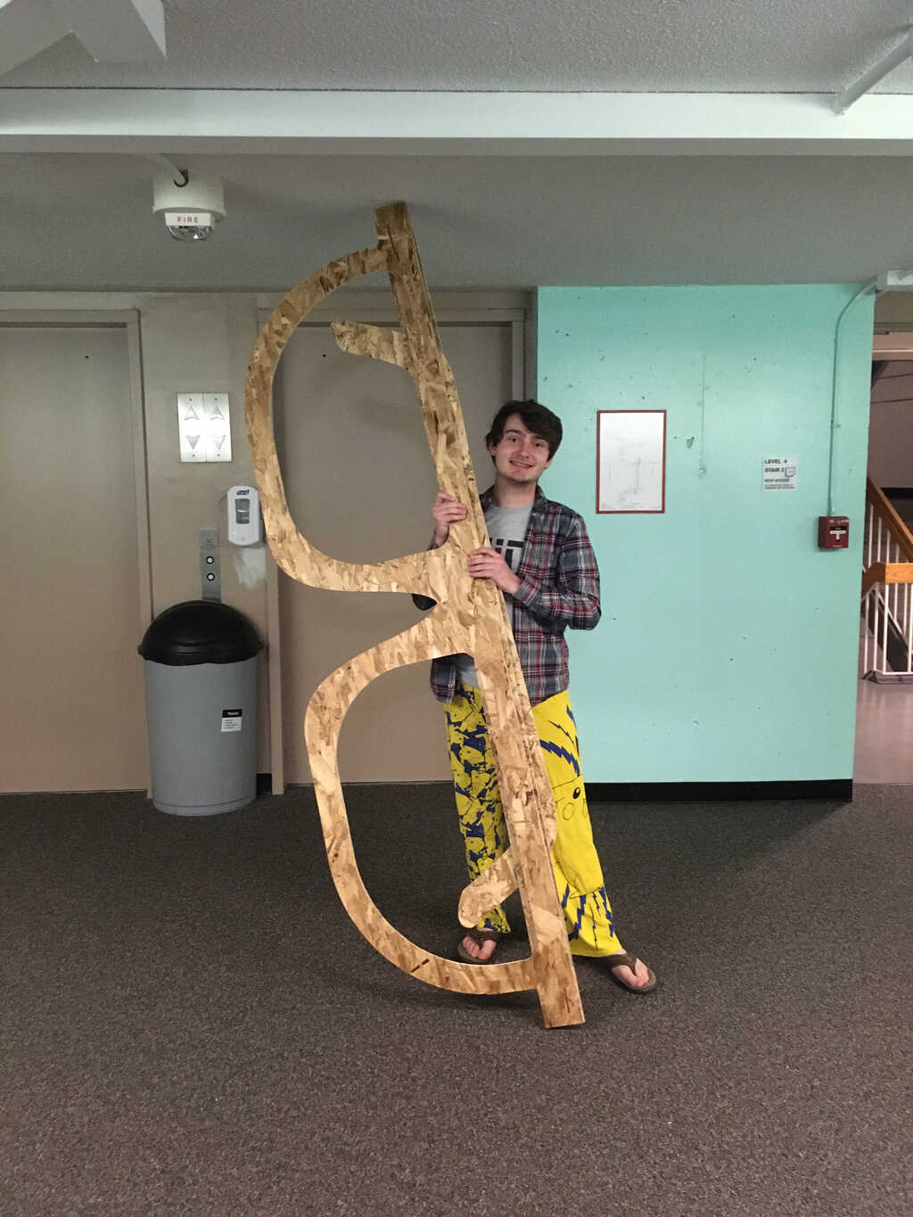
They can stand on their own!
The de-skinning process had a lot of scrap, so I made sure to clean it all up!
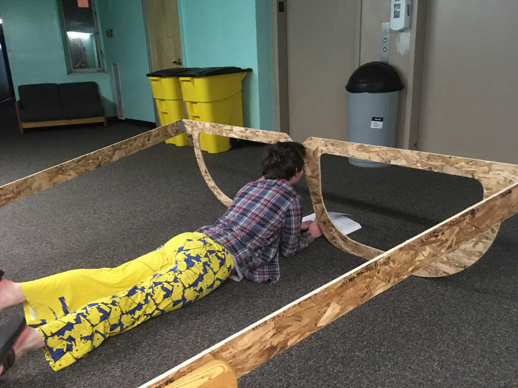
Now, enjoy a fashion shoot with my new glasses, ft. Make: AVR Programming!
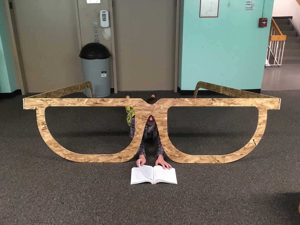
Hmm, I think this prescription might be a bit too strong
This was a fun week!
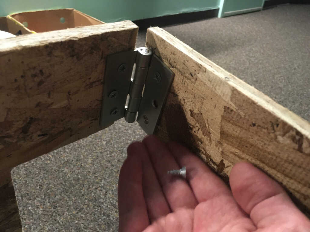
I was warned that I may need glue in tangent with the wood screws, and sure enough, during the photoshoot, one of the screws worked its way out. I'll have to add more security to it for sure.