The Ring Display
This week I made a ring display. Why?
- It's a display that fits the form factor of a hexagon
- It's simple to interface with (just use a microcontroller as the brains)
- It let me practice complex routing
Charlieplexing
Before I get into the juicy details about the LED ring display I made, let's get some background information out of the way.
To create a simple ring LED display, I wanted to use 12 LEDs. (Perfect for a clock!) While that's fine and dandy, 12 LEDs means 12 outputs and 12 resistors; that just isn't going to cut it on the small footprint of my boards. In lecture this past week, we learned about something called Charlieplexing. It allows for more LEDs using fewer pins and resistors. Perfect! Here's how it works:
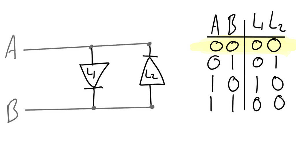
First, you hook two LED's up to the same pins, with one of them reversed. Since LEDs are diodes, current will only flow through one direction. When neither of the pins are on, no current is flowing, so neither LED is on.
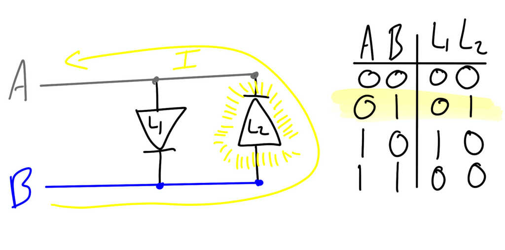
If we only turn on one of the pins, here pin B, then we have current flowing from B to A. This current will get blocked by L1, but flow through L2, causing it to shine!
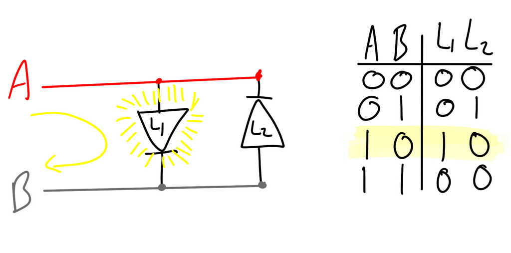
Similarly, by turning on pin A and leaving pin B off, current will flow through L1.
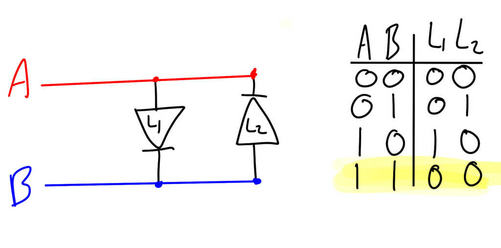
However, if both A and B are turned on, then there's no net current and neither LED will light.
Well, this isn't that useful because we're still using two pins for two LEDs. However, if we scale it up, we can get much more out of it. By arranging the LEDs in an array, it looks like we can get N² LEDs using only N pins!
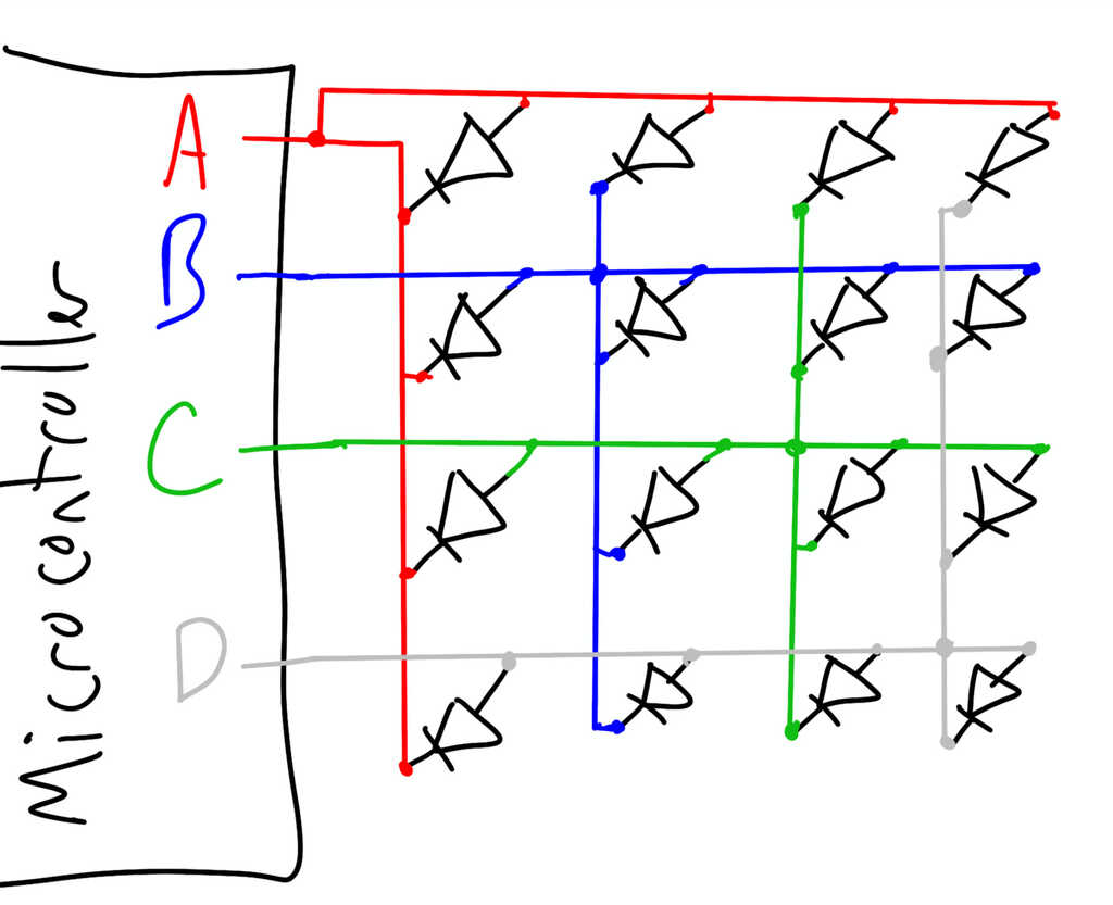
Not so fast! If we look, some of the pins intersect with themselves. For example, in the top left corner, the LED is wired to pin A on both ends. If both pins provide the same output (as in the earlier example), then the LED won't light. So that means any LEDs on the intersections are useless.
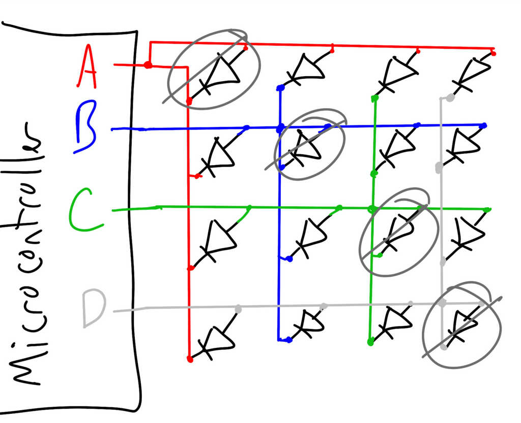
This means we get N*(N-1) LEDs using N pins. That's still a lot! With those LEDs gone, we get an effective array that looks like this:
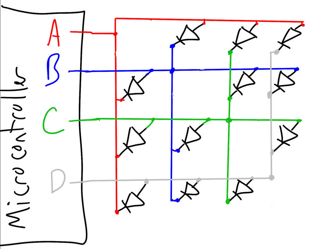
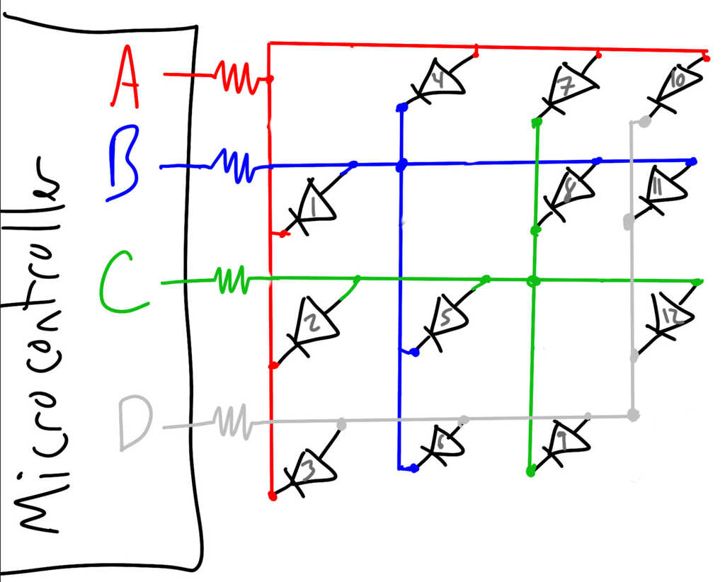
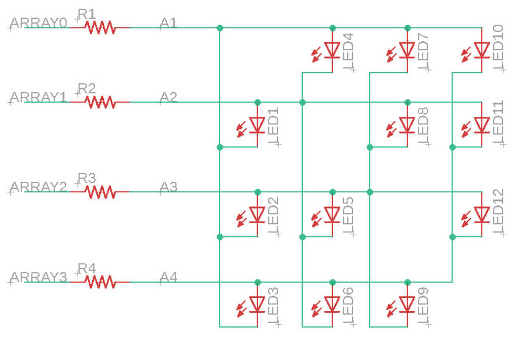
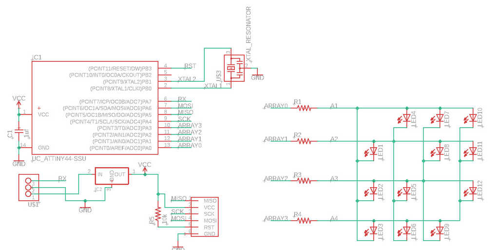
Now you might be thinking, "this is fine, but aren't we missing something? Don't LEDs need resistors?" And you'd be totally right. So first, we only have to add in a resistor at each pin. (Don't believe me? Look at this example, A->B = A->Resistor->LED->Resistor->B. Trace it on the next schematic!) If you noticed, we have 12 LEDs as well (using our math from before, N=4 pins, 4*(4-1)=12); exactly as many as we need for our display.
Planning the Board
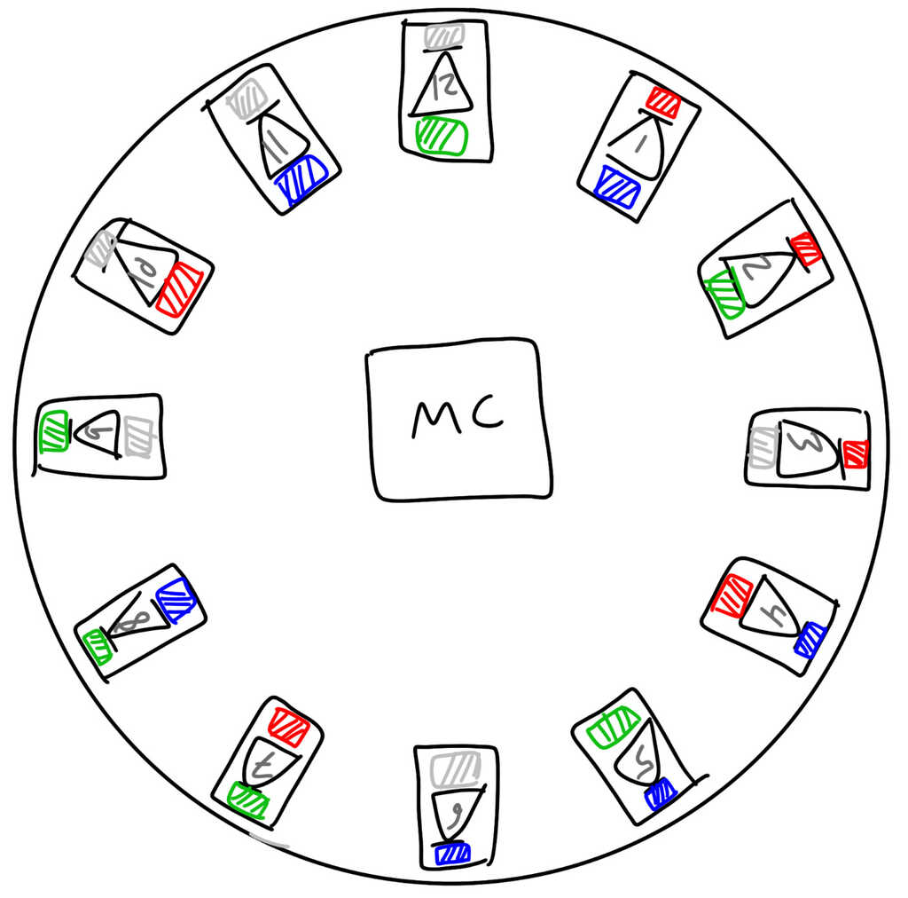
Alright, we've got enough LEDs, we've got our resistors, but this is still a square! Making it a circle is pretty straightforward, we just move all of the LEDs into a circular pattern. Here, I've colored the nodes of the LEDs to match the pins they're connected to.
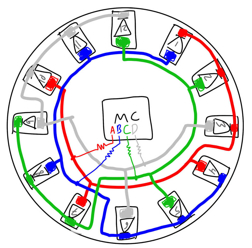
Sweet, all that's left to do is wire it up! (This is pretty easy when I'm just drawing, but it's a real pain to do on an actual board in Eagle.)
So, how do we get this in Eagle, anyways? The Charlieplexed array is exactly as we drew it, no problem at all!
That's easy enough, now it's just up to arranging these in a circle. If only there was an easy way to do that...
(Spoiler, there is)
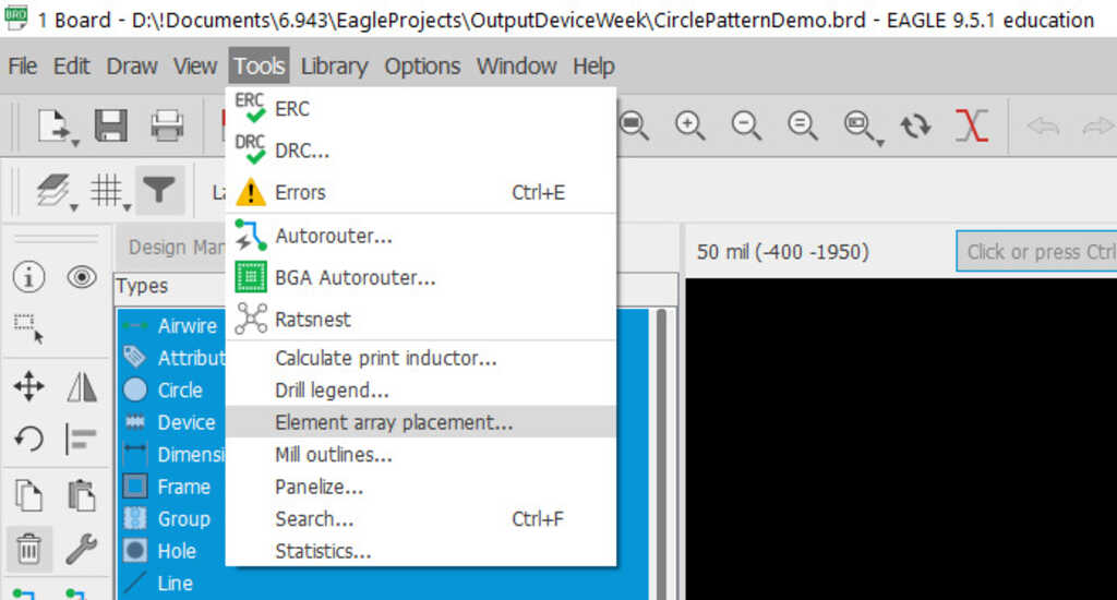
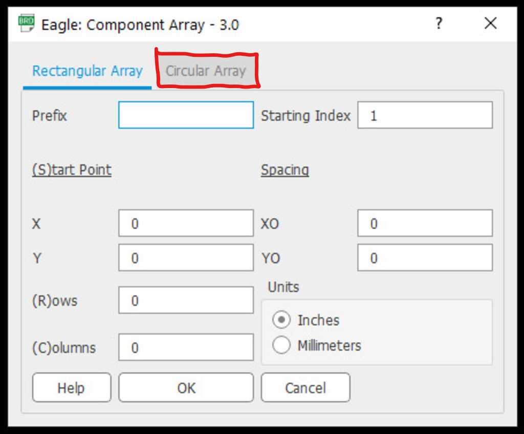
Luckily for us, Eagle has an "Element array placement" tool that we can use. You can access it via Tools->Element array placement... in the menu.
The first menu that pops up is for Rectangular Array. We don't want that, so click on the Circular Array tab.
In this menu, there are a bunch of different options. Here's an example:
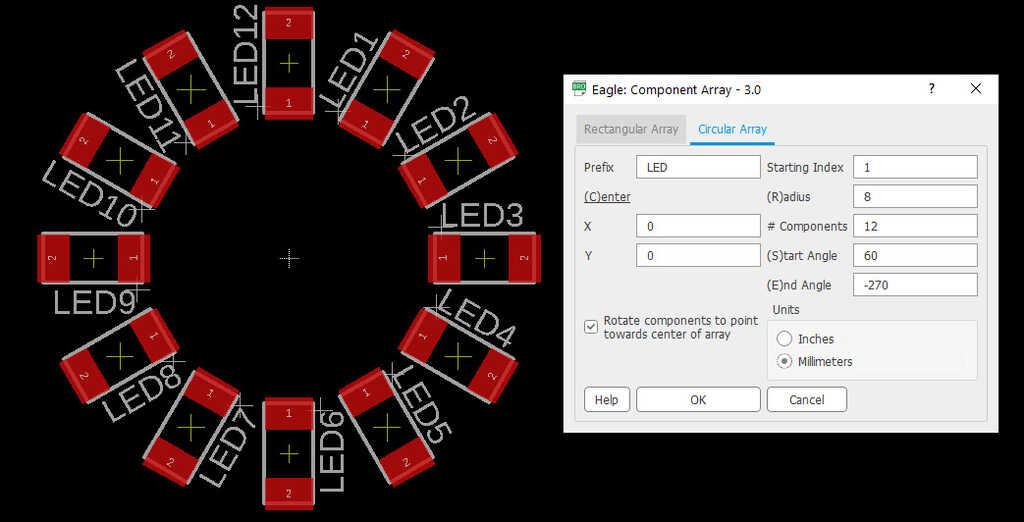
But what do each of these mean? Let's get into the details:
- Prefix: This tells Eagle what subset of parts you're going to put into the array, based on how you named them. Here, I named all of my parts LED (with a number following them), so I used LED as the parameter.
- Starting Index: This tells Eagle which element of the subset to start with. For me, since I set the index to 1, Eagle will start with LED1 and count up from there.
- (C)enter: These are the X and Y coordinates of the center of the circle. For this example, it's centered around the origin (X=0,Y=0).
- (R)adius: This is the radius of the circle. The center of each component will be placed on this circle. In this example, it's 8mm.
- # Components: This is the number of components Eagle will iterate through. With it set to 12, Eagle will go from LED1 to LED12.
- (S)tart and (E)nd Angles: These are the angles (in degrees) between which Eagle will place the components. For example, if Start Angle is 0 and End Angle is 180, then the first component will be placed at 0°, and the last component at 180°. The rest of the components will be evenly spaced between them. Things to note:
- 0° is directly to the right.
- Increasing angle goes counterclockwise.
- The range of angles is -360°->360°.
- The Start Angle can be greater than the End Angle, and doing so will place components clockwise.
- Rotate components...: Check this to point the components towards the center of the circle. Here, it's checked.
- Units: Straightforward, the units for the radius and center. I used mm.
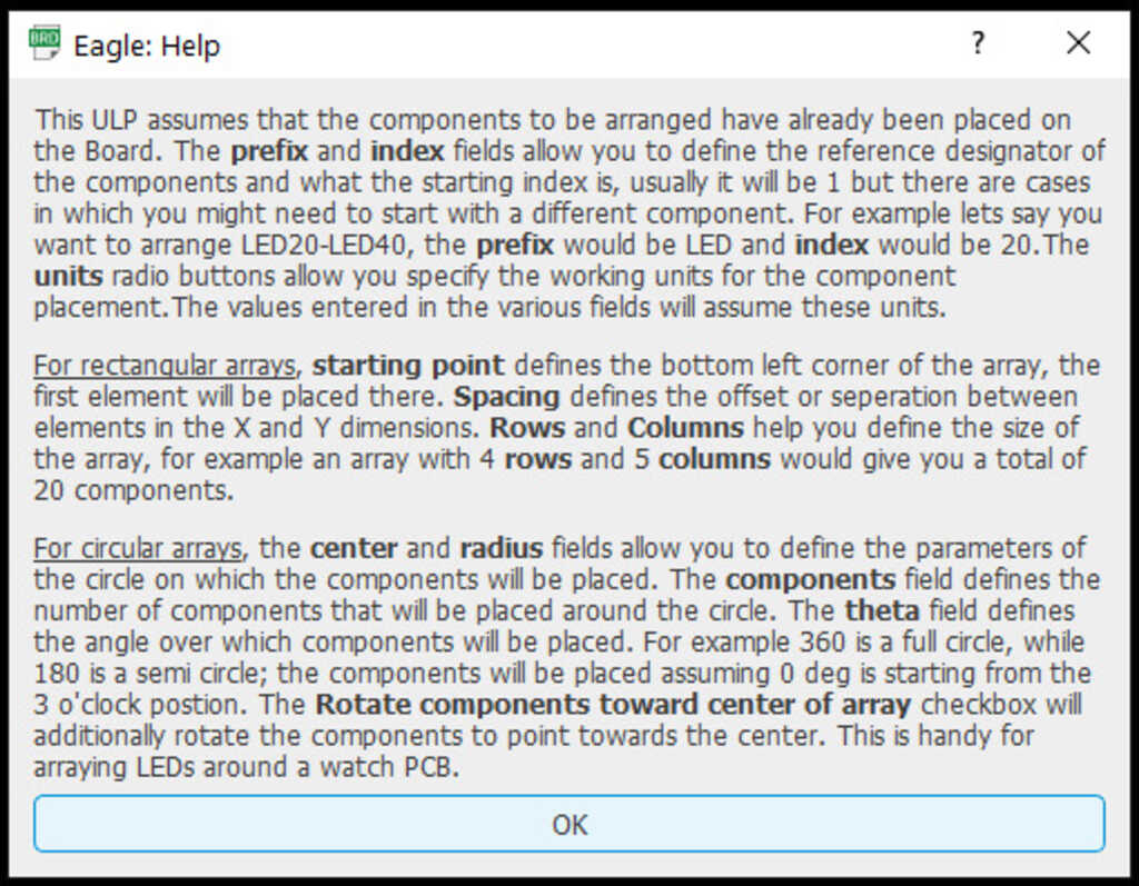
OK, and you're all set! If you click Help, you're presented with a description of how this works. Well explained, so it can be useful if you ever forget.
With all of this out of the way, now it's just down to drawing the board, placing components, and figuring out how to wire everything up.
Designing the Board
Before we get started, let's take a look at what happens if we take a naive approach. Rather than using Charlieplexing, what would happen if we just used one LED per pin? This:
While that routing is pretty simple, this design requires 8 more resistors and 8 more pins on a microcontroller. Yikes!
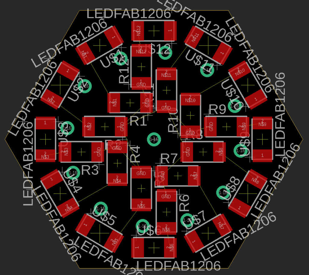
Instead of doing that, let's take the principles we learned and put them to good use: (Download here)
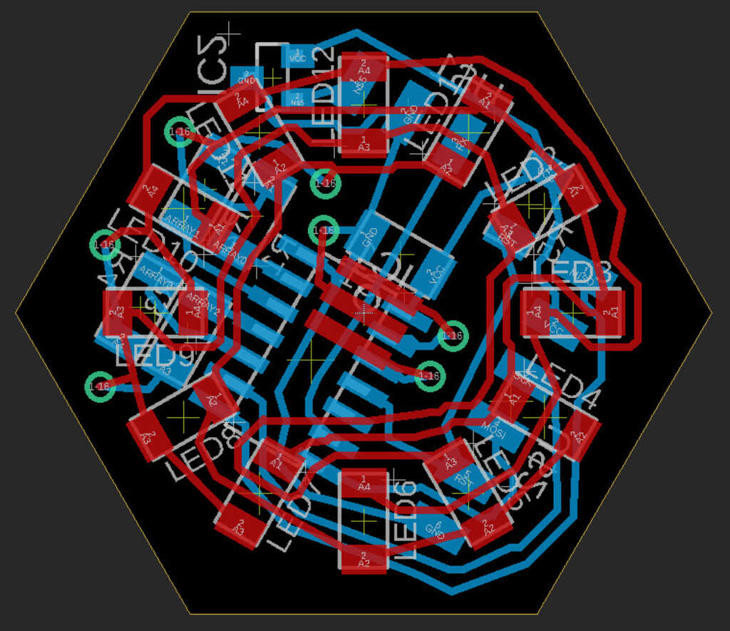
Whoah! That board is a little to complex to read like this. Let's look at each side.
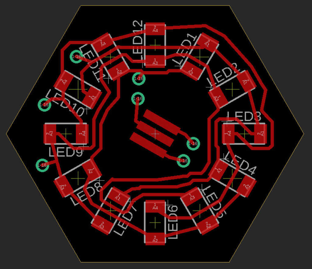
The Top
The top is much simpler in terms of components, but pretty crazy in terms of routing. I used the technique described above to place the LEDs in a circle.
- 12× blue 1206 LED
- 1× 20.0MHz resonator
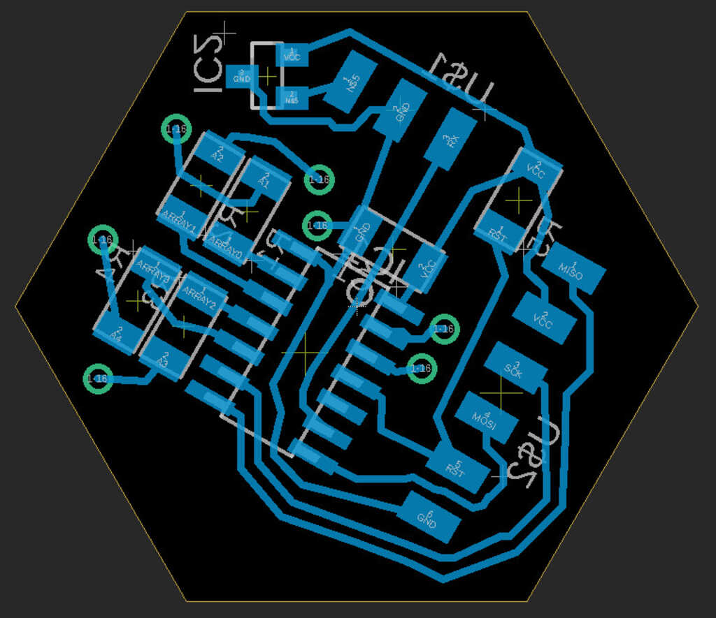
The Bottom
- 4× 1206 499Ω resistors (for the LEDs)
- 1× 1206 10kΩ resistor (rst pullup)
- 1× 1206 1μF bypass capacitor
- 1× SOT23 3.3V 100mA linear voltage regulator
(I'm pretty sure I've fried mine, and I forgot a capacitor on the output. To resolve this, you can put a diode on the input so current won't go backwards. Still need a capacitor, though. - 1× ATTiny44
- 1× 3 pin Male header (VCC, GND, RX)
- 1× 6 pin Male header (ISP programming)
Assembling the Board
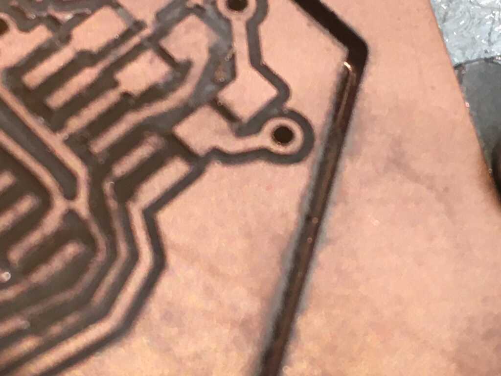
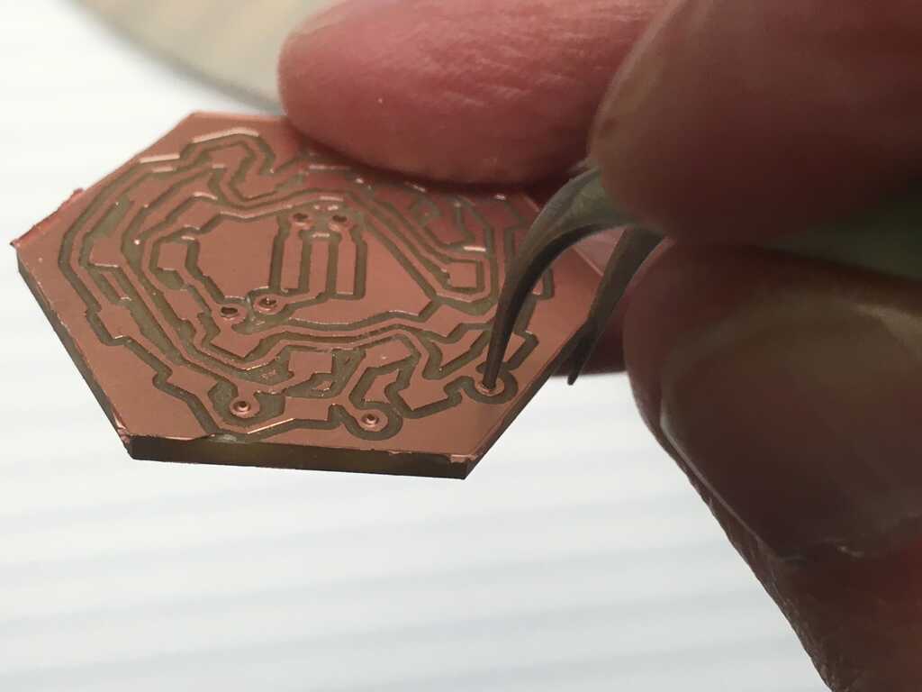
As usual, I used the Othermill since the alignment plate makes double-sided boards a breeze. Not as usual, the debris from the mill was building up as it cut the outline of the board material. While not so big of a deal, once the job completed I realized that the mill hadn't cut all the way through. You can see the bottom copper layer in the second image. Something went wrong with the calibration of the end mill, such as a tiny speck of debris between the end mill and the calibration plate, that caused it to not go all the way down.

I also learned this time that you're supposed to run holes on both sides of the board. I didn't know that (despite having done multiple holed boards already), and had to spend some time with tweezers poking out the holes before I could rivet them.
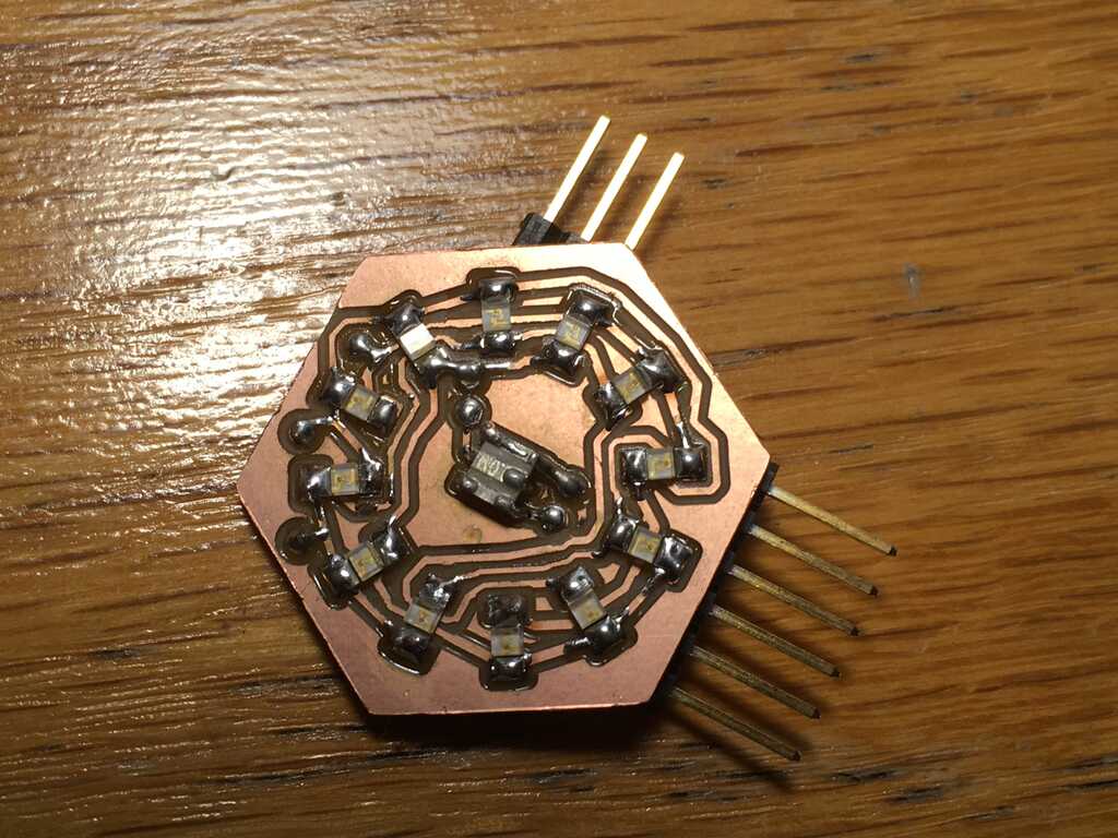
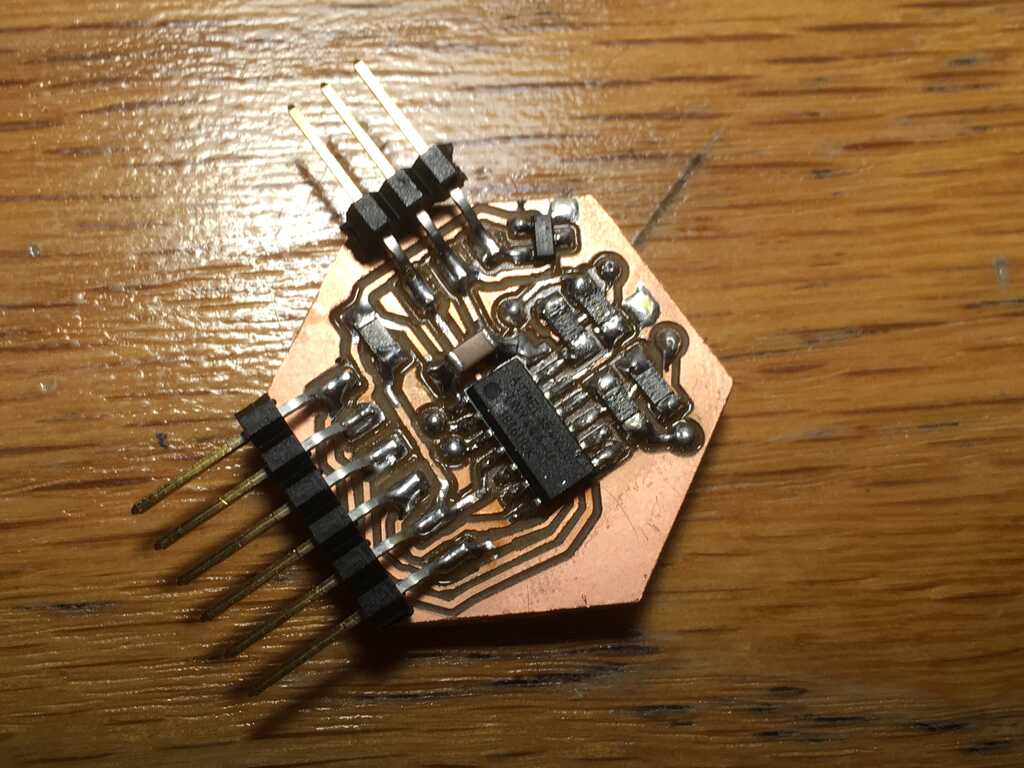
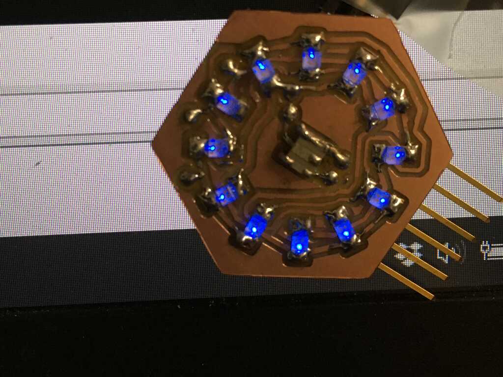
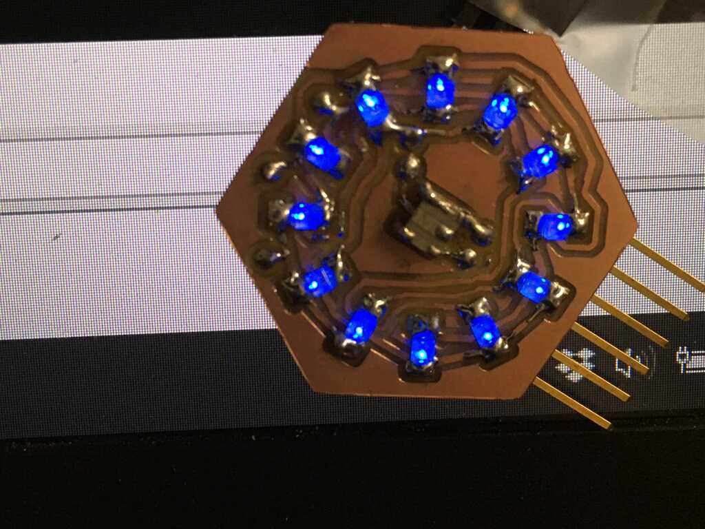
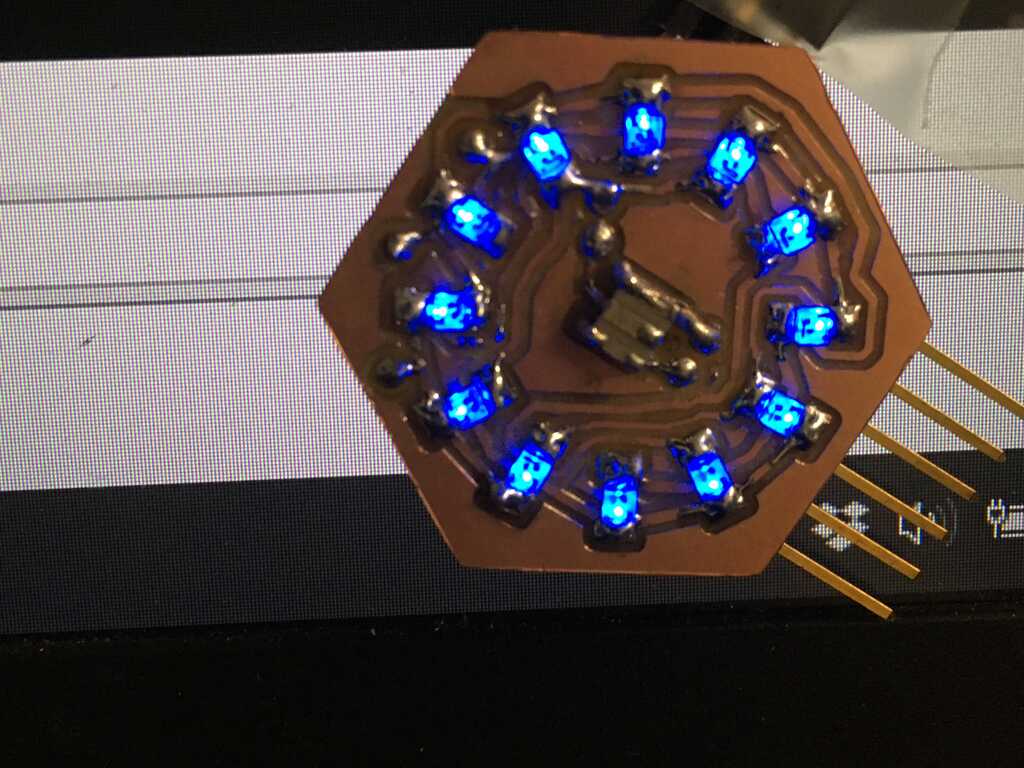
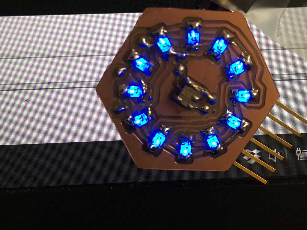
And here's what the board looks like with all of the components in place:
Testing the Board
The first step to testing the board was to guarantee that all of the connections were correct. I did so by using a power supply and running current from a "row" to a "column" (these are still Charlieplexed), and seeing which LEDs light up. In a correct setup, only one LED would light at a time. In these images, I'm keeping the ground consistent and moving the voltage source to different positions.
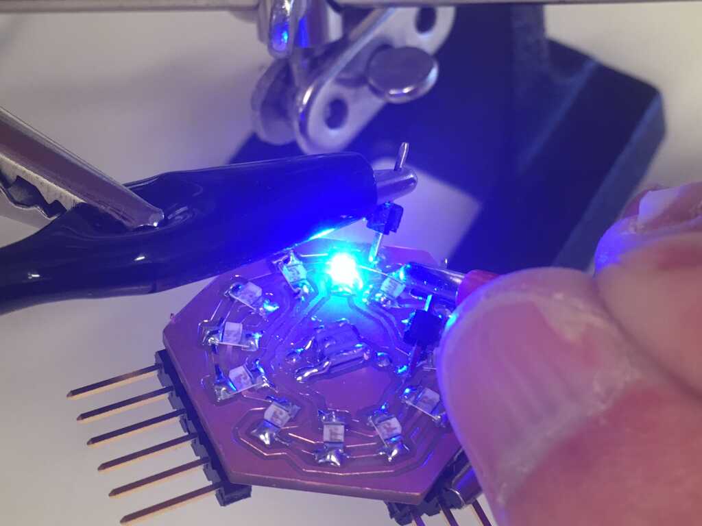
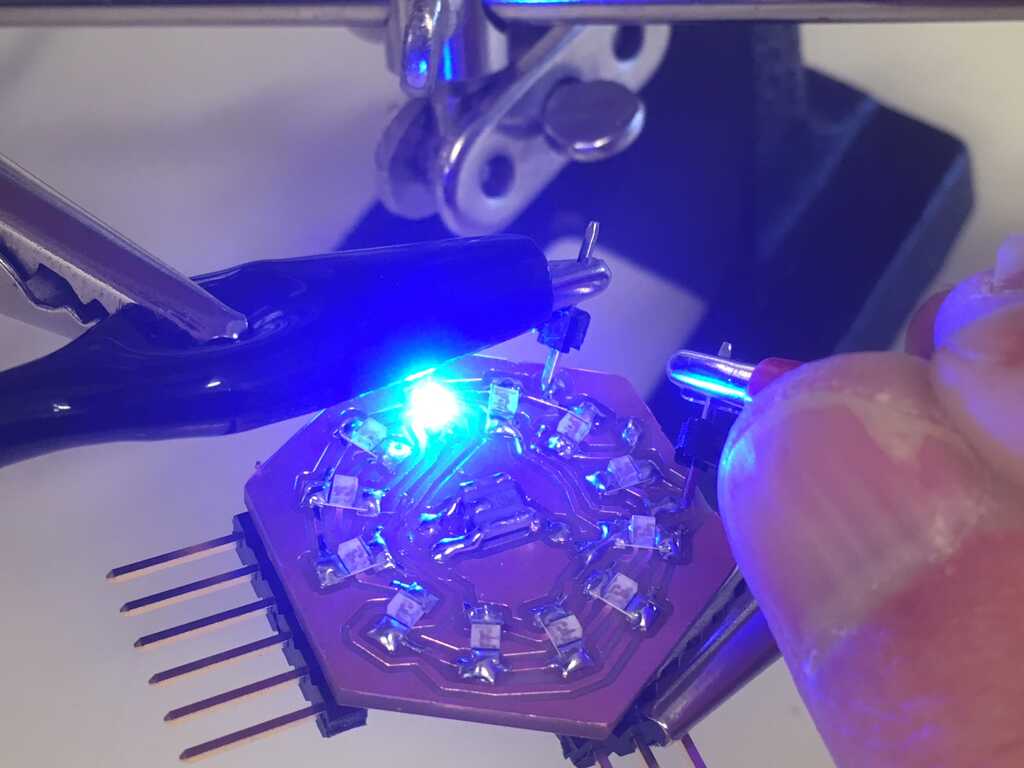
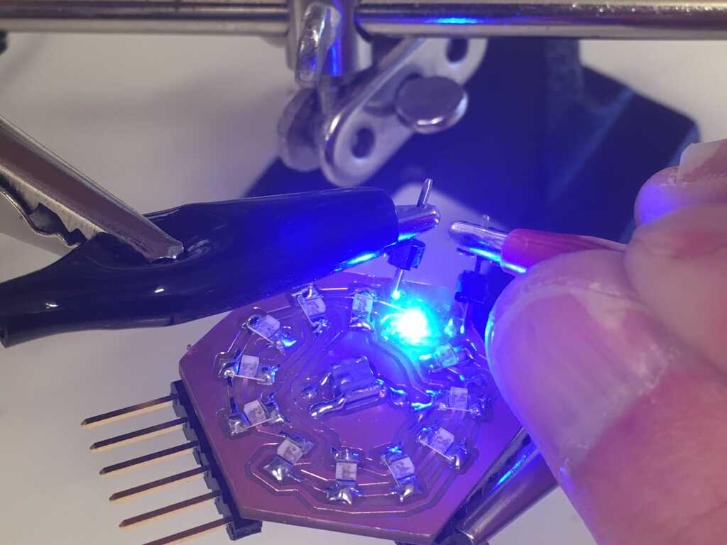
Unfortunately, not all of the rows and columns behaved like this. Sometimes, two LEDs would light at the same time while others wouldn't light at all because the "rows" were connected. I was able to sniff these out, and they were due to the mill not completing a full path. I had to do a substantial amount of post-processing to clean it up. There was one trace I didn't catch until I was actually running code, which really sucked.
With Code
Speaking of code, I was also able to test the circuit by slightly modifying Neil's Charlieplexing example. Since the principles of Charlieplexing remained the same, all I had to do was change some pins to get it to work. By coincidence, the way I set up the LEDs meant that they were in the same order as Neil's code! But enough testing, let's get into the real code.
Coding the Display
This is the final version of the code.
There are quite a few considerations and iterations that went into this final product, but let's just look at what's in this code right now.
Timing
The 20MHz resonator is actually there for serial communication, but we can use it for some fast timing as well. To keep track of time, I have an interrupt running. How fast, you might ask? Let's calculate it:
- Clock Cycle: 20MHz (from Makefile)
- Prescaled by 1/8 to 2.5MHz (timer initialization)
- 1/2,500,000 seconds per tick
- Interrupt fires every 100 ticks
- 1/25,000 seconds between each call
- One millisecond is 25 ticks
millis every 25 interrupt calls (I'm not using Arduino libraries, so no name conflicts).
Serial
An important feature is being able to tell the display to update. I initially tried to use pieces from Neil's serial interrupt example, but I just couldn't get it to work. I assume that there were clashes with the two interrupts and timings. Because I didn't include a TX pin, I couldn't verify what was going on. Instead, I used Neil's serial polling example. Since it just wastes time in a while loop checking a pin, it worked fairly well. The 115200 baud rate was very inconsistent, so I opted for 9600 instead with a bit_delay_time of 101 μs. Slightly higher delays, such as 106 μs, would frequently lose bits of data.
This example uses serial, but I plan on using I²C for communication later on, so I'll have a two-way communication stream.
Brightness
Starting out, the LEDs had two values: on, or off. But we can do better than that. Using a PWM of sorts, we're able to get a range of values. But how fast is that? Let's do some more math:
- 25,000 pixel updates per second
- One rotation around the display takes 12 updates, so we get ~2083 fps.
- Assuming we want at least 30 fps (image fusion in the eyes), the resolution of our PWM could be up to 69 bins.
- For a nice even number, I decided to go with 32 bins. That comes out to ~65 fps, while also providing a very nice gradient to choose from.
Board Connections
It's important to know what connects to what, right? Take a look:
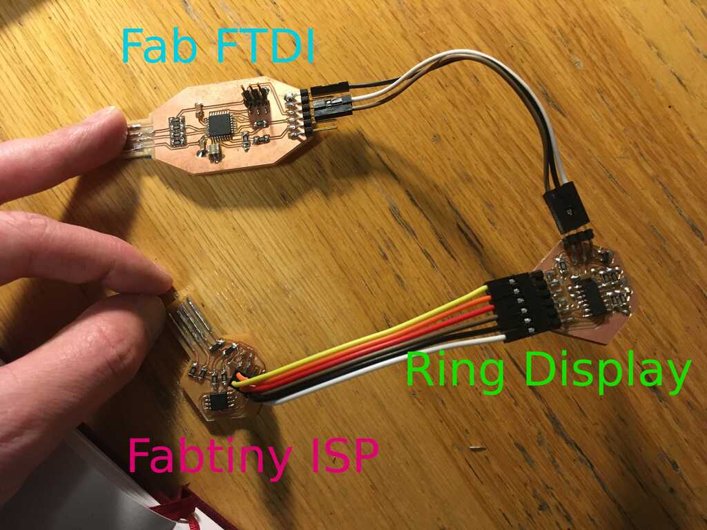
The ring display is what we made this week, but why are the other two in play?
- Fab FTDI: Provides power, ground, and an RX serial connection.
- Fabtiny ISP: Programs the display, of course!
Display Patterns
Alright, enough background info, let's really get into the meat of this week: what can the display display? Why don't I just show you?
A lot happened here, let's break it down:
- The user sends a character to the display
- The display parses the character and changes state
- While in that state, the disply updates accordingly
- Set
- Character: :
- Function: The base state. This state waits to receive a character, and then switches to the appropriate state. This state can interrupt any state.
- Pattern: Blinks on and off every ~1/2 second to indicate it's waiting for an input.
- Off
- Character: o
- Function: Turns off all of the LEDs.
- Pattern: All off.
- Notify
- Character: n
- Function: Notifying the user. This state can interrupt any state. Once complete, changes the state to Off.
- Pattern: Quickly pulses all LEDs 3 times, then turns off.
- On
- Character: O
- Function: Turns on all of the LEDs.
- Pattern: All on.
- Echo
- Character: e
- Function: Echoes the binary Ascii value of any input character. 0 is off, 1 is on
- Pattern: Low bit is at 12 o'clock, high bit is at 11 o'clock.
- Pulse
- Character: p
- Function: Interpolates all of the LEDs between on and off.
- Pattern: Slowly pulses all LEDs.
- Ring
- Character: r or R
- Function: Rotates a brightness gradient around the display. r runs the ring counter-clockwise, and R runs the ring clockwise
- Pattern: One LED is off, the one on the opposite side is at max brightness. The rest in between interpolate to that. The pattern is shifted left (r) or right (R).
- Stars
- Character: s
- Function: Randomly pulse LEDs. Uses one of Microsoft's LCGs to generate a random star.
- Pattern: Pulses one random LED at a time. Once an LED finishes, another one is picked at random.
- Clock_Set
- Character: c
- Function: Sets the time. The user enters the time, one character at a time, in this order: _X:XX, X_:XX, XX:_X, XX:X_. Once complete, moves to Clock_Run.
- Pattern: Blinks the LEDs based on how many numbers are left to input:
- _X:XX - 11011
- X_:XX - 11010
- XX:_X - 11000
- XX:X_ - 10000
- Clock_Run
- Character: [no character]
- Function: Tells the time. For the hour hand, each LED is an hour. The minute and second hands are divided into 5 increments. For example, 20 minutes is the dimmest of the 4 o'clock LED, and 24 minutes is the brightest. Updates every 1/2 second.
- Pattern:
- Set brightness of the hour hand
- Set brightness of the minute hand
- Determines brightness of the second hand
- t<0.5s, LED is unchanged
- t>=0.5s, LED brightness is set to second hand