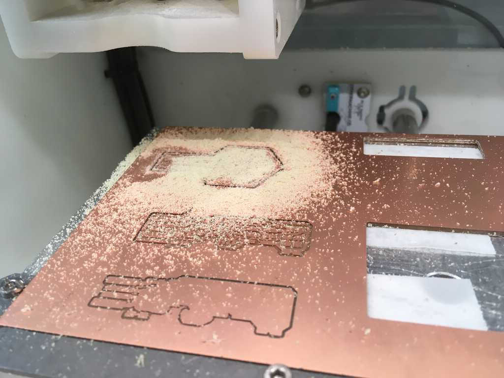
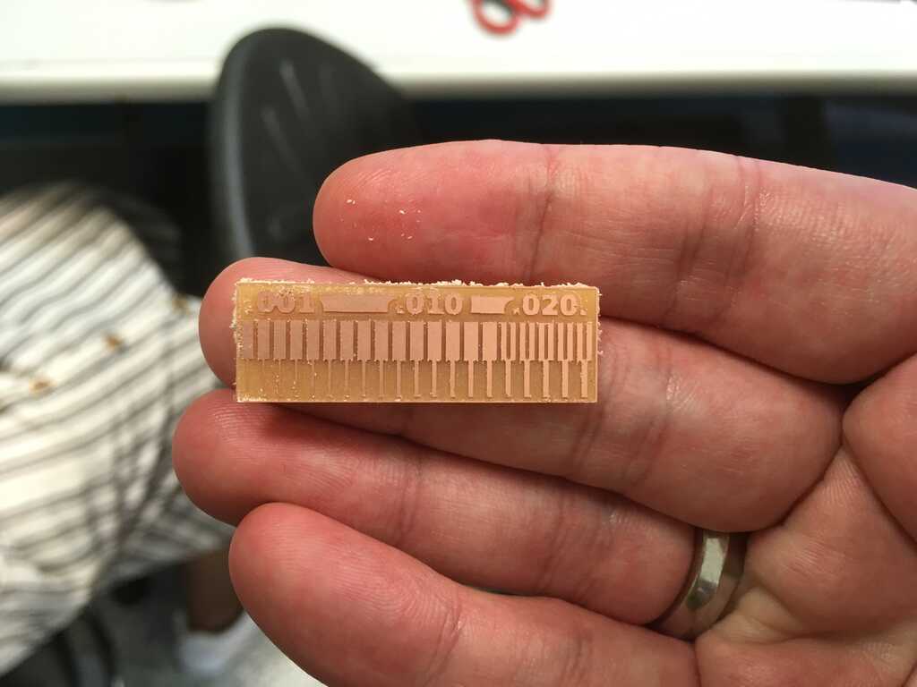
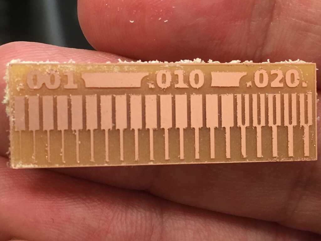
Using the Roland mill, we cut out the test piece using the 1/64" bit. We determined we could get very small traces, but to guarantee reliability we decided to say that 0.010" would be as small as we should go. For interiors, we're limited to the width of the bit, which is 0.015625". So realistically speaking, 0.016" is totally manageable.
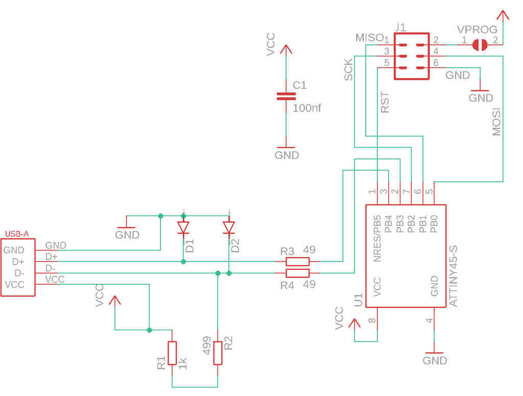
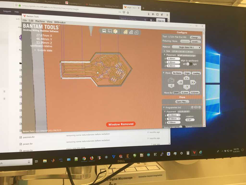
For whatever reason, I thought we were supposed to design our own version of the provided circuit, so I did. Using Eagle, I used the same circuit elements as Brian, with the exception of the two LEDs and their corresponding resistors. Wanting to minimize the footprint of my circuit, I decided that they weren't necessary. To ensure compatibility of my circuit with the parts in the lab, I had to find packages that matched the components available in the EDS.
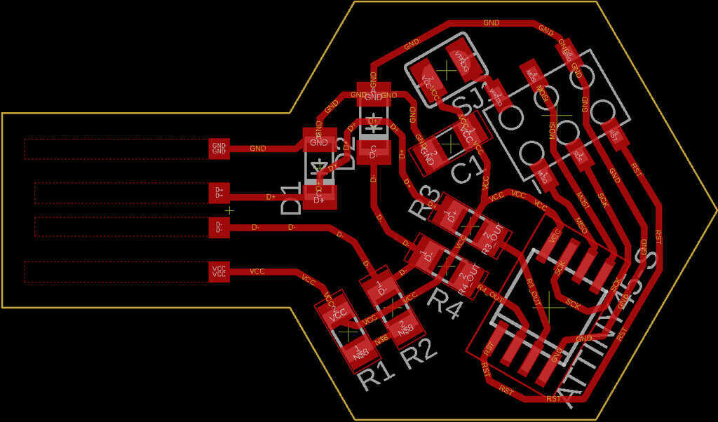
Since I plan on making a bunch of hexagon modules for the final project, I wanted to practice by making the programmer into a hexagonal shape. One of the first things I had to do before placing components and routing the traces was to draw the board outline. With some research, I found that there was a fairly straightforward solution: calcualate the points of a hexagon (this python script) and create an outline based on those points (this Eagle script).
Next was adding in a USB connector. I found these dimensions for a USB connector, and created a library file based on this. The way I got it to work in the final design was to draw polygons attached to the USB pads, and give them the same signal name. The dotted lines on the board design are these polygons
With my design spec of 0.01" traces and 0.016" gaps, the jumper I had originally selected was too narrow to cut out, so I had to look for a wider jumper.
Organizing all of the components and navigating a maze of traces was an arduous process, but eventually it all came together. Very satisfying.
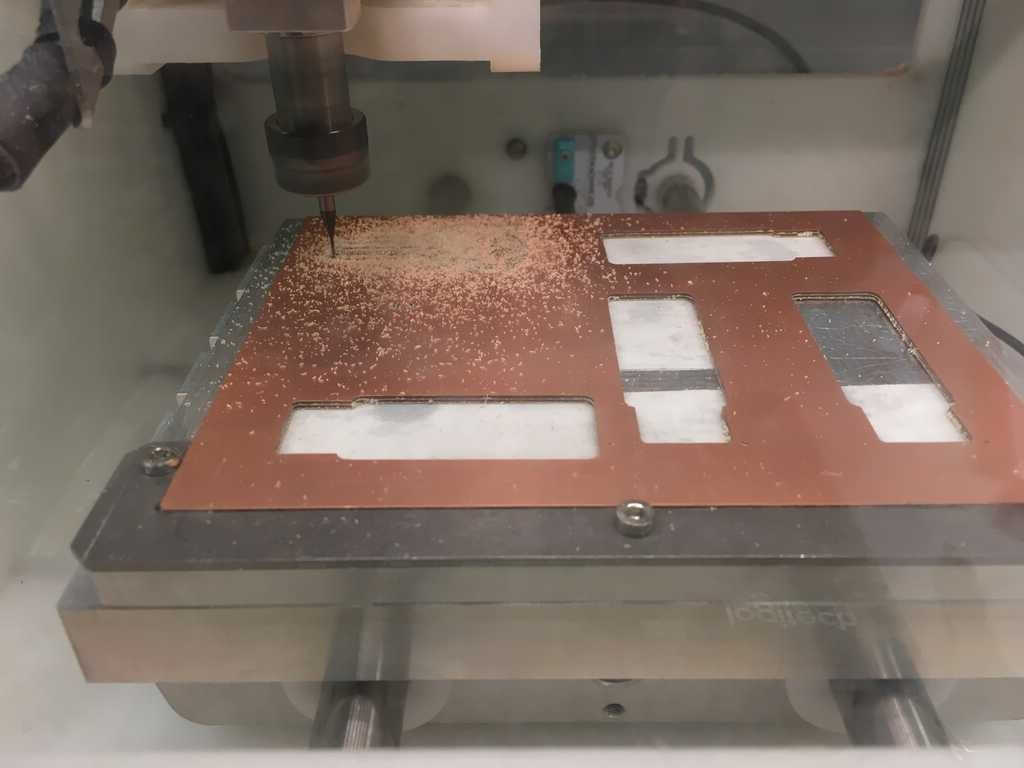
In the EDS, we have two mills. I used the Othermill, which allows you to cut directly using an Eagle file. This will be useful for cutting out double-sided boards later. Another feature of this mill is that it will cut out details with the smallest bit available first, and then--after switching out the bit manually--cut larger areas of the board.
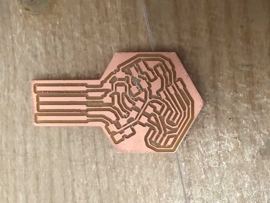
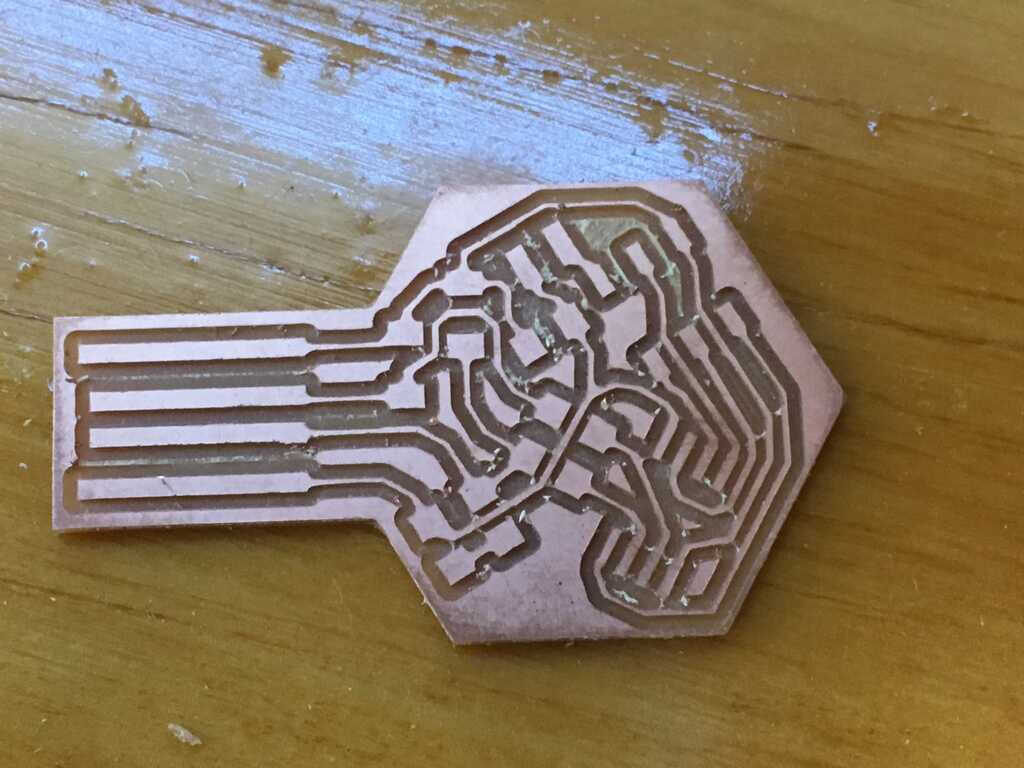
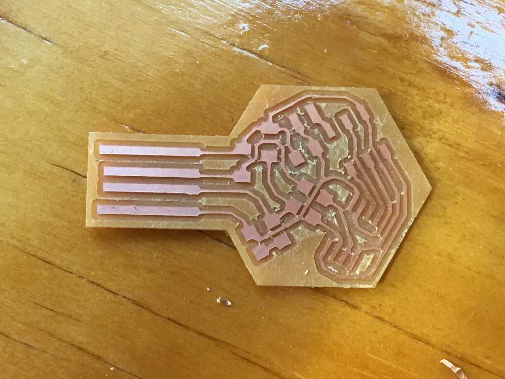
Let's see how the piece turned out:
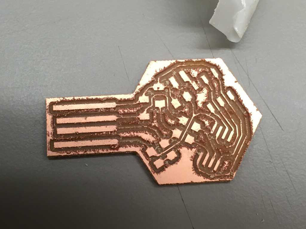
Oh no. This is no good at all. The bit really chewed this piece up. Almost everything came out intact, but on the right side there's a trace that got torn off. Well, the piece can be sanded down, but I think it's back to the drawing board for now.
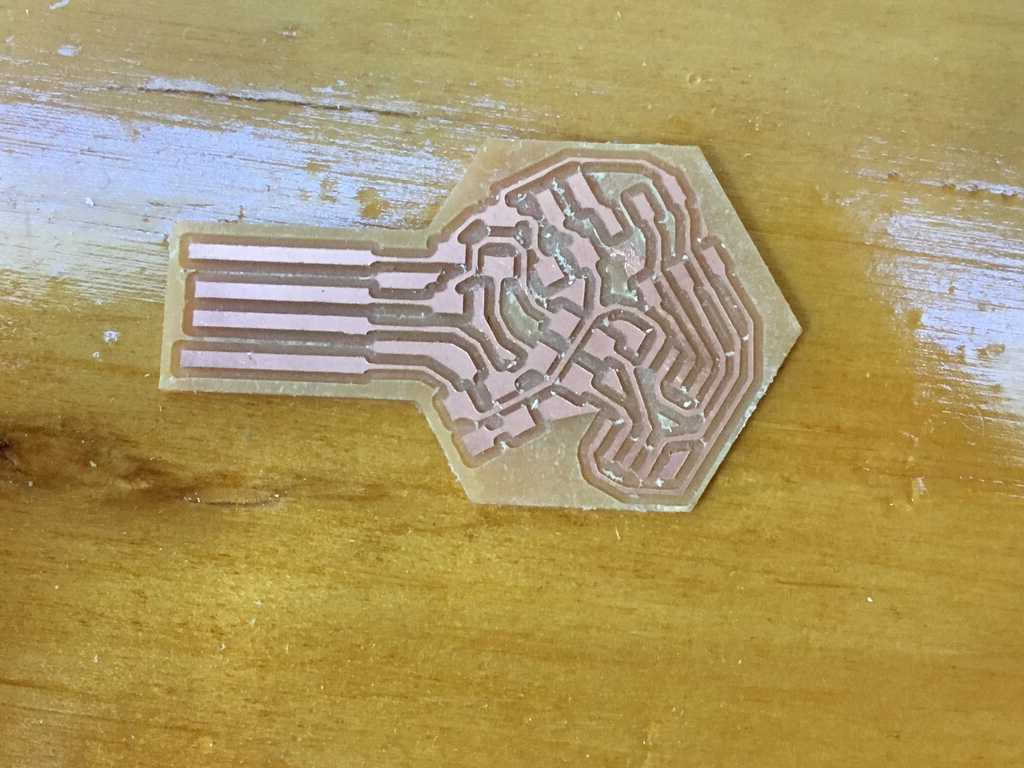
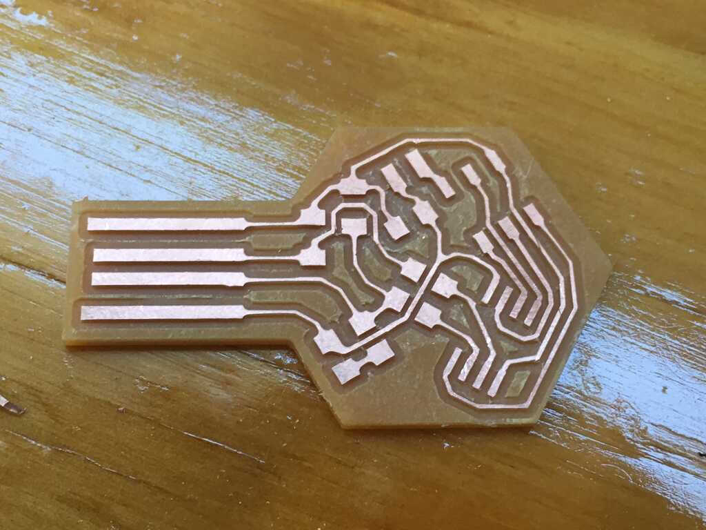
I went in and updated the trace widths to 0.016" so they stood a better chance against this bad bit. This meant I had to reconsider my routing a bit, especially under the resistors since the traces barely fit. Let's give it another shot.
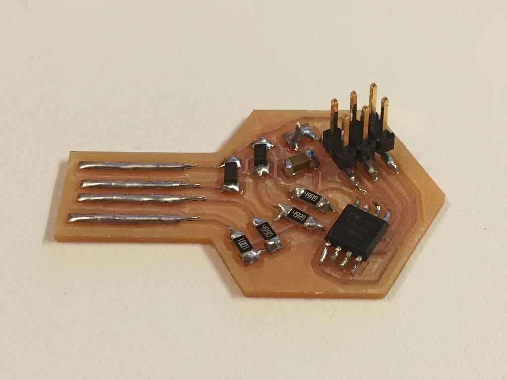
And after some sanding:
Phew, that's much better. There's a bunch of excess copper, and some of it needs to be removed. While we're at it, why not remove all of the excess copper to clean it up a bit?
To be safe, I decided to test all of the connections with a multimeter. Most lines looked good, but I realized I was getting a short somewhere. Take a look for yourself:
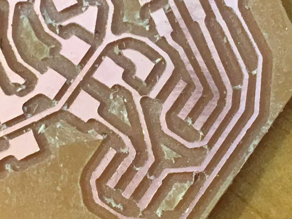
Ohhh, that's no good! That tiny bit of copper would really screw everything up. It had to go. Let's finish cleaning up:
Oh yeah. That's incredibly satisfying. Now it's time to give this circuit life.
For the circuit, I needed these components:
- 2x 3.3v Zener Diodes
- 2x 49Ω resistors
- 1x 499Ω resistor1
- 1x 1kΩ resistor1
- 1x 100nf Capacitor*
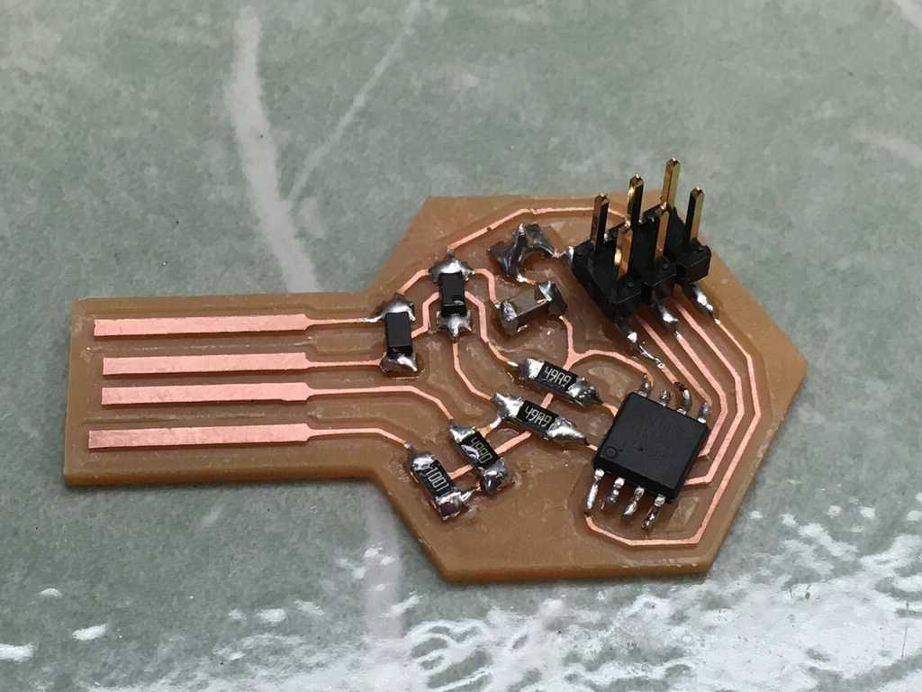
- 1x 6 pin header
- 1x ATTiny45
*The capacitor was labelled as 0.1µF instead of 100nf.
Here they are placed in their appropriate spots:
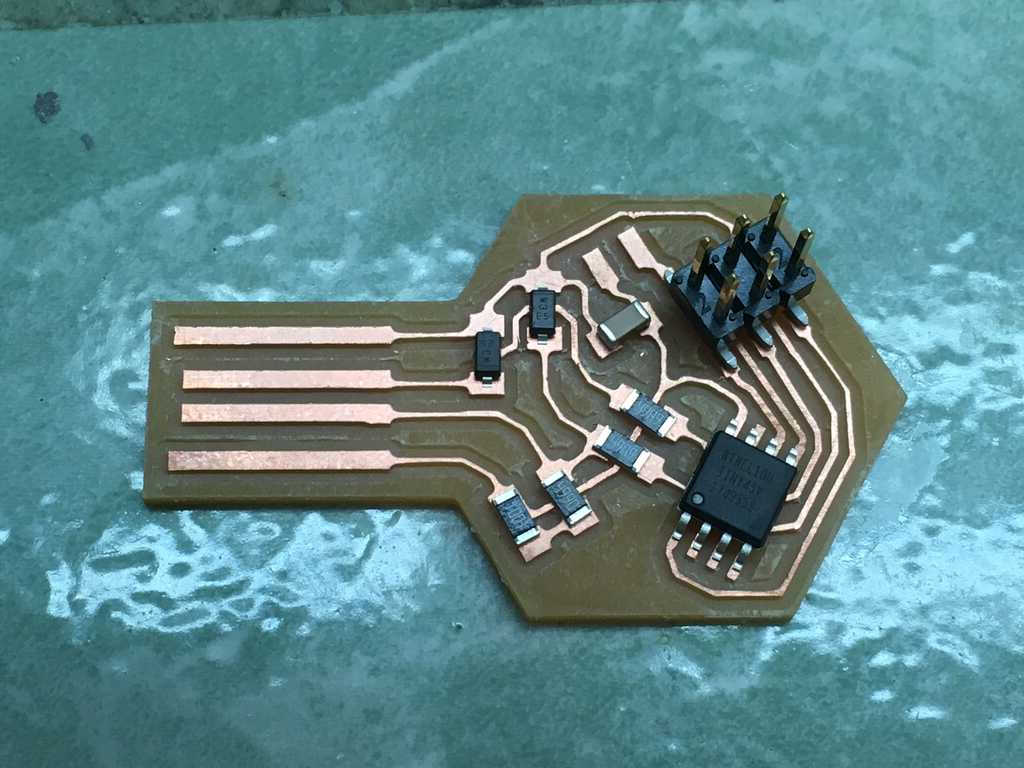
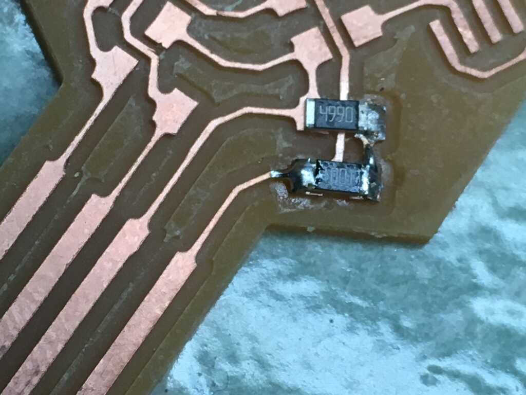
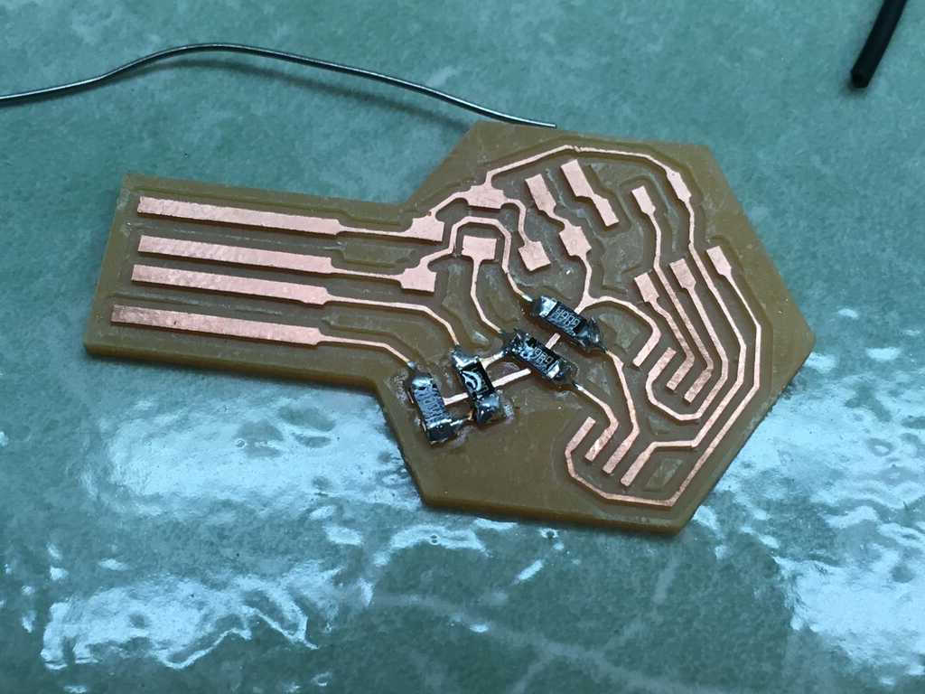
Let's get to soldering:
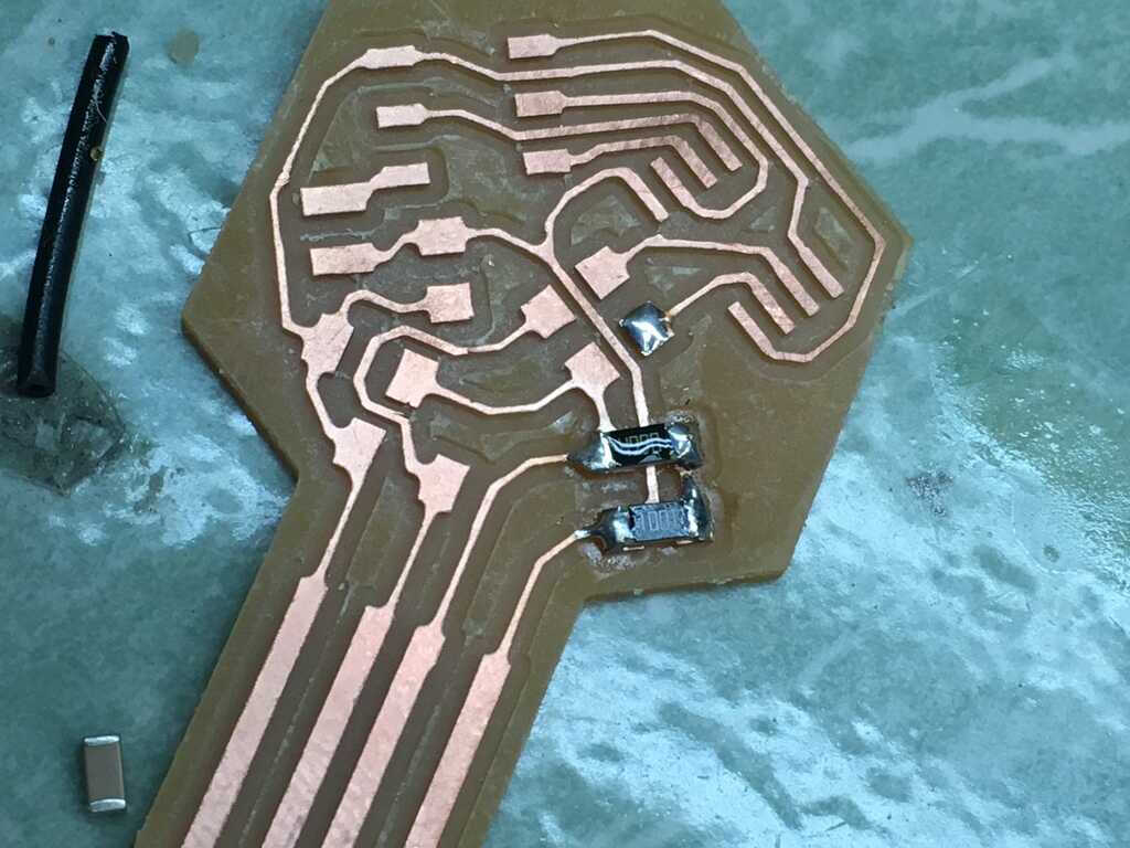
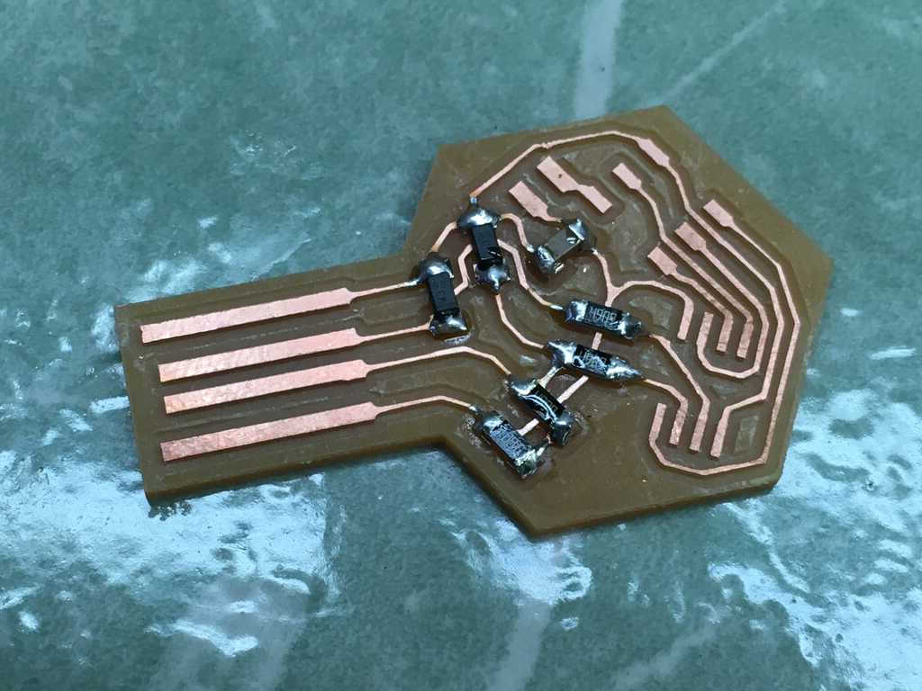
With the resistors complete, it was time to put the diodes on.
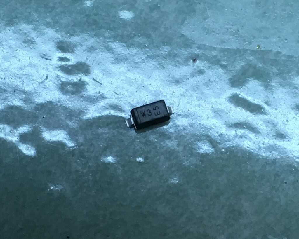
You see that line on the left? That indicates the direction of the diode. Very important, but also very hard to see. Every time I dropped the diode (which was fairly often), I had to look at it for some time to figure out which way it was facing before trying to put it on the board again. Anyways, back to soldering.
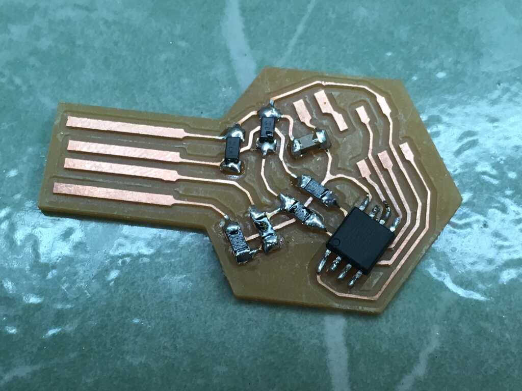
And that's everything! Remember how I said I didn't include the LEDs? Well, they were supposed to be included to indicate the status of the board. Without them, I wouldn't be able to tell if anything was happening to the board when it's connected. This meant I needed to test every trace to make sure there weren't any shorts and I was getting properly expected values (e.g. resistance) across them. From what I could tell, everything was looking good.
Again, we're back to Brian's page to figure out how to let this board think. The guide is pretty straightforward, but there's a dead link for getting the toolchain on Windows. This is the toolchain he was referring to.
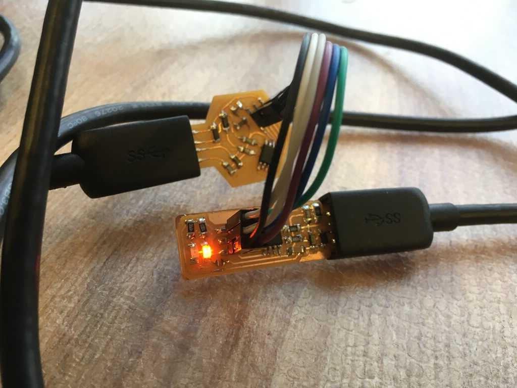
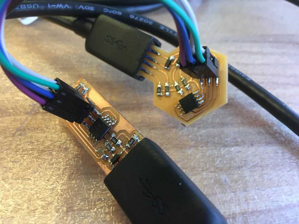
Hooking up my board to the programmer:
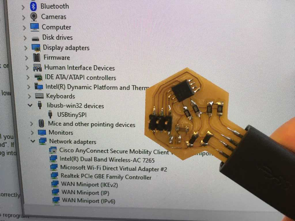
After running the appropriate commands, my board should be programmed now. It shows up as a USB device, so that's promising!
All that's left now is to pop the fuses and try to program another device:
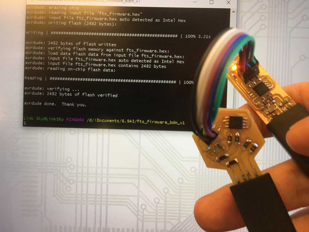
And there we have it! I've successfully created a programmer!