
Dynamic Coral Lamp
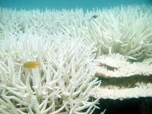
Inspired by my love of the marine environment + cool lighting, I wanted to create a dynamic coral lamp that responds to human disturbances. I envision the lamp existing in a baseline 'happy' state if left untouched or unmoved. However, as it's increasingly disturbed, it would progressively enter an 'unhappy' state. The mood change would be indicated via LEDs, and as the lamp grows unhappier, it would turn white (i.e. coral bleaching). If left undisturbed however, the lamp would eventually be 'happy', returning to its normal color. My goal is for the lamp to act as an educational metaphor for how real-life coral react to negative environmental disturbances, as well as display their ability to recover from bleaching events if their environment returns to a healthy state.
Click here, to see some previous ideas!
Initially, I was really struggling to resonate with a project idea. This was primarily due to the fact I wanted to tie in a nature theme with an item I would use after the class ended. Sometime during the midterm check-ins, I had semi-developed an idea I was complacent with, and I based my Week 9/10 assignments (input/output devices) on the assumption I would probably build it. However, despite the fact that I'd ordered materials for my previous idea, I had a flash of inspiration late one night in EDS for a coral lamp that would respond to touch and physical shaking. Similar to my previous idea, it incorporated artistic elements inspired by the natural world while still being an object I would genuinely use after the class ended.
This new idea would allow me to learn a lot about CADing organic shapes and designs. As someone who entered the class with little CAD experience, this learning opportunity immensely appealed to me. Given how well it fit all of my interests, I decided to jump ship and commit.
My initial vision was to create coral structures out of clear resin, and internally light them using addressable LEDS such that they diffused through the the structure. This idea also partially came to me because I had just found myself in possession of a free liter of Formlabs clear resin, and had access to a Formlabs printer at Sea Grant, where I UROP. While I had very recently done my first Formlabs print, I hadn't had much further experience with resin printers and thought that resin printing was an ideal approach for the organic shapes I was trying to create and this project would allow me to gain experience with resin printing.
Check out the video at the top of this page for a partial CAD timelapse!
As soon as I opened Fusion360, I realized I had underestimated how much time it would take me to create realistic coral structures in CAD. I started first by googling various types of coral. Knowing my perfectionist tendencies, I decided to go for a mix between imitating real-life corals, but also add my own artistic flairs that were not necessarily realistic.
I initially debated between creating a single structure, or having multiple. After ten minutes perusing Google, I realized I couldn't commit to one type of coral. Additionally, one reason I'm drawn to coral is their sheer diversity, and it would be a shame if I couldn't showcase a sliver of that in my final project.
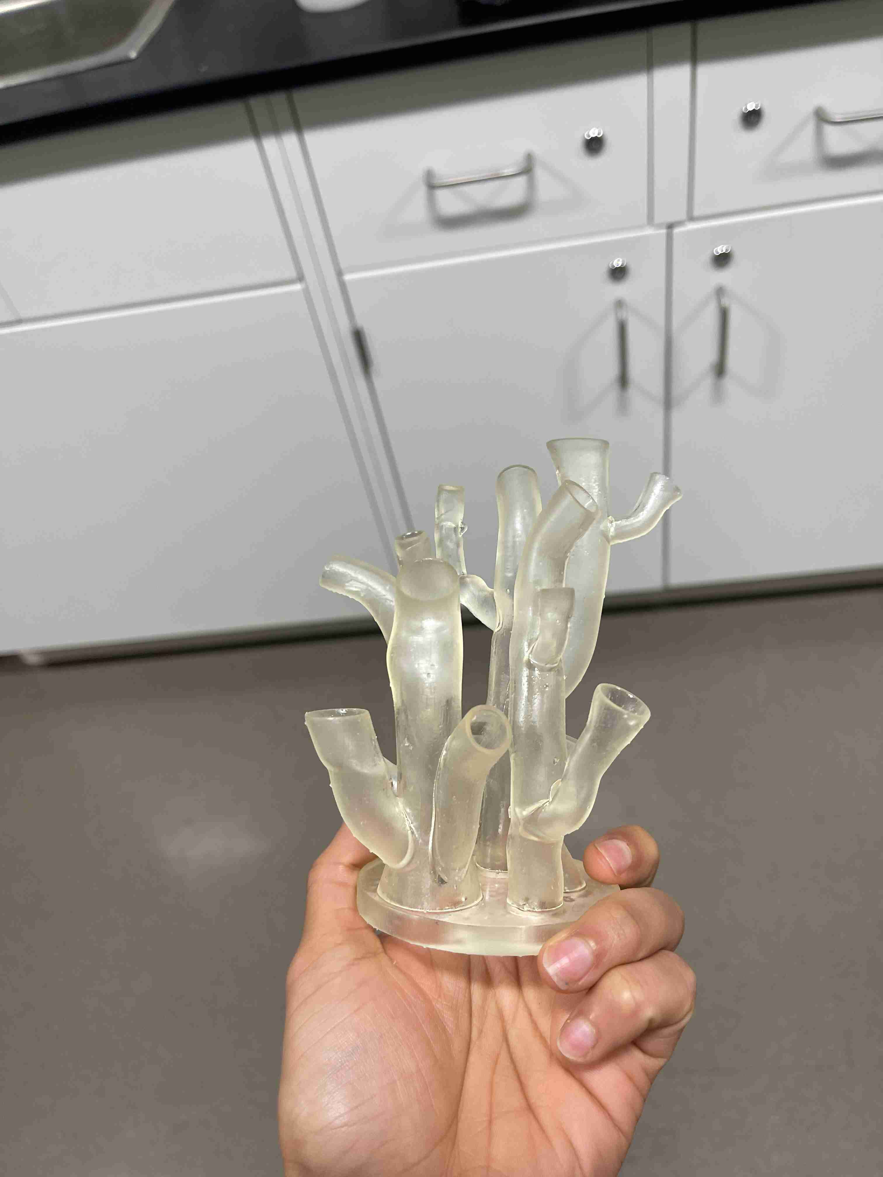
After some more research, I decided on going with a tube coral shape for my first structure.
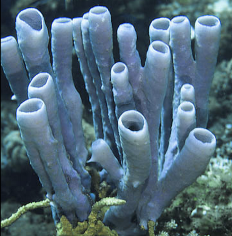
I also googled some tutorials on creating coral models in CAD. Needless to say, they all assumed viewers had a high baseline knowledge of CAD software and I couldn't keep up with them for the life of me. Instead, I went back to Fusion360 and stubbornly messed around with the 'Create Form' functionality in the Design tab for a few hours. My first few attempts inevitably looked like piles of horse poop, but eventually, I finally got a shape that looked like this:
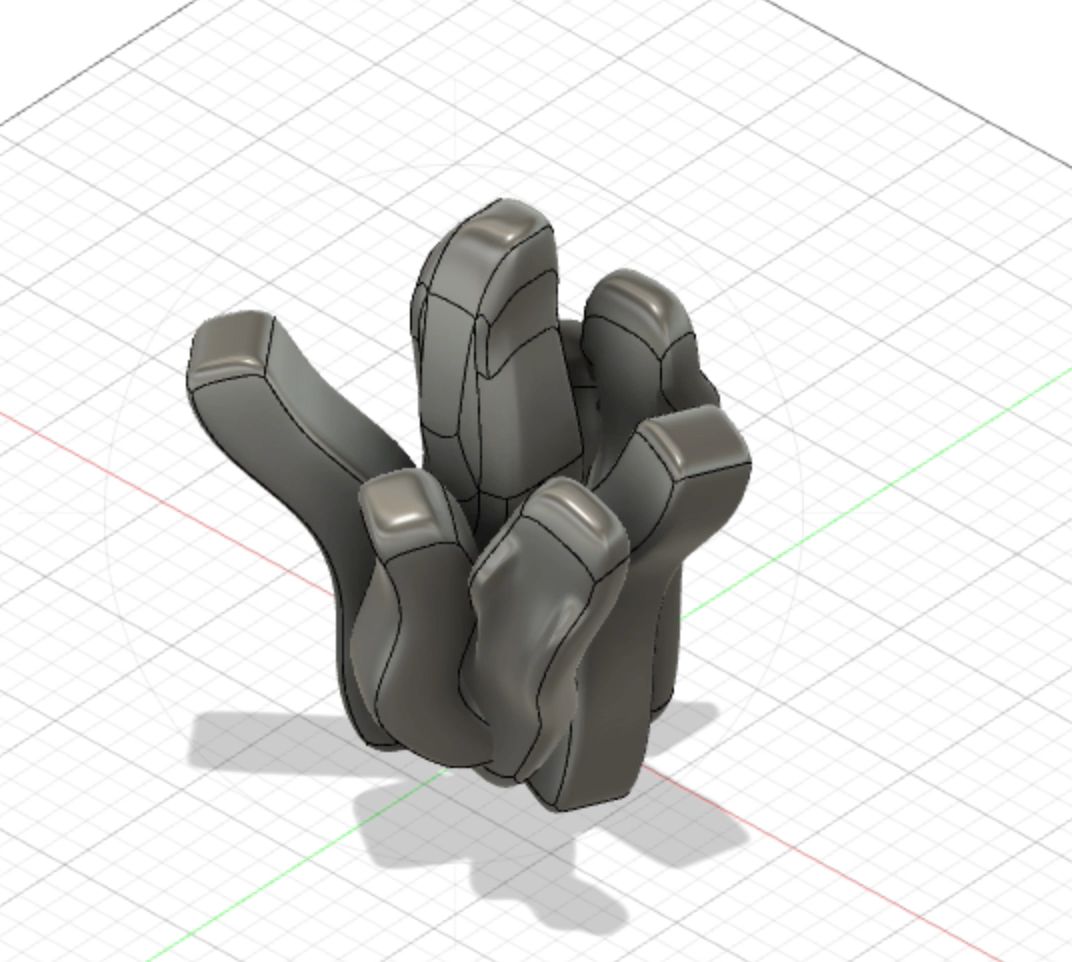
I then realized I needed the tops and bottoms of the coral to be open (aha actually tube-like instead of closed vaguely-cylindrical shapes) so I could embed LEDS and the light would be able to escape. I finally caved and chatted with Anthony and Alec about how best to create organic shapes in CAD, and both of them suggested Blender. Unfortunately, Blender confused me even more, but Alec kindly took the time to walk me through a few tutorials.
The tutorials were immensely helpful. While I was still confused by Blender, I was immediately able to translate the steps Alec showed me to Fusion360. The process was still time-consuming, but there was now light at the end of the tunnel! To create tube coral, I followed these steps:
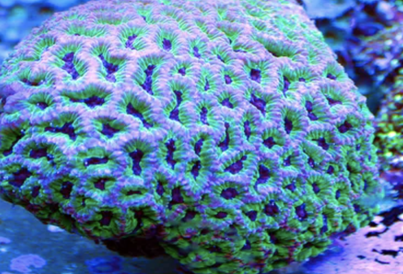
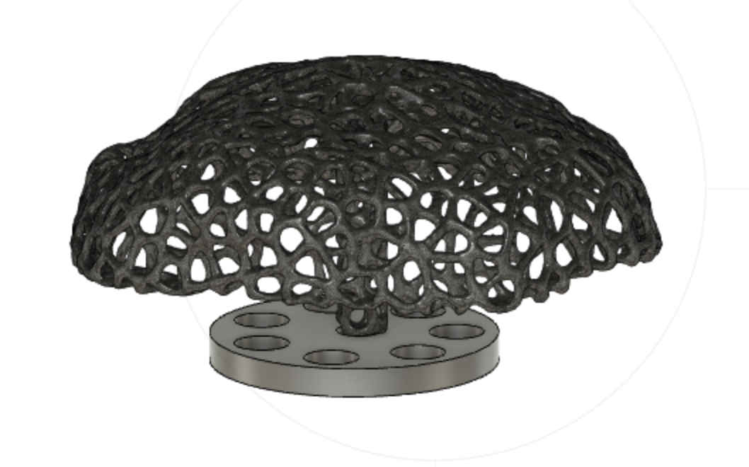
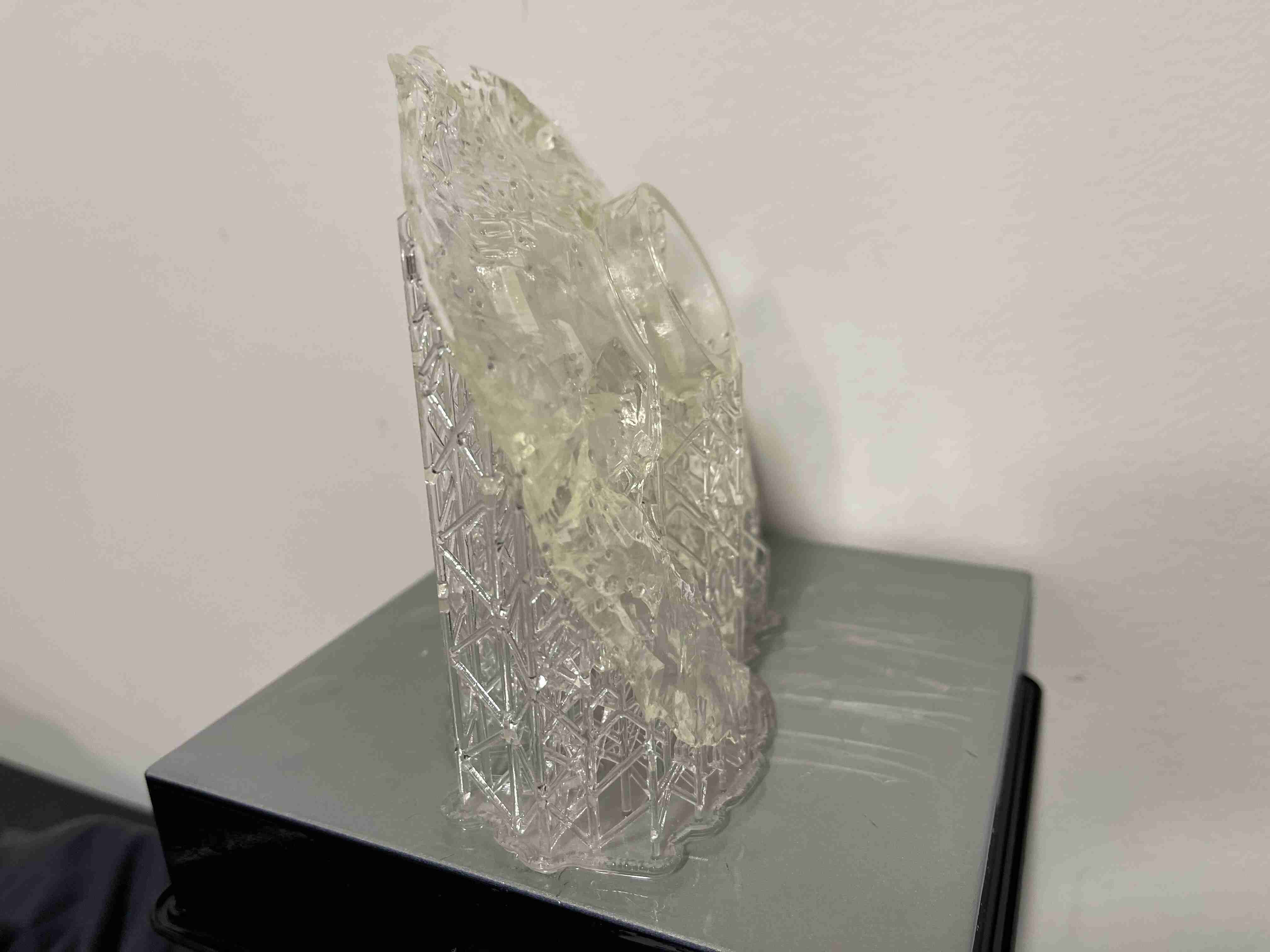
The next coral design I decided to try was inspired by the Voronoi pattern. I had posted in the issue tracker for more advice on ceating coral shapes, and Olivia Seow commented with this approach. She directed me to try this website, which allows you to apply a Voronoi effect to a 3D model. After the immensely time-consuming tube coral, this seemed like an easy way to create another another structure, and I thought these were somewhat similar to brain coral.
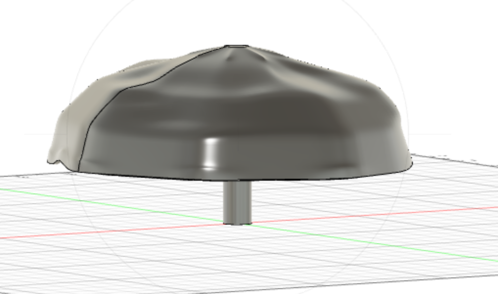
Now that I had a lot of familiarity with the 'Form' functionality in Fusion, I whipped up a quick blobby lamp shade shape and passed it through the Voronator. The end result was pretty cool, would project a cool pattern once illuminated.
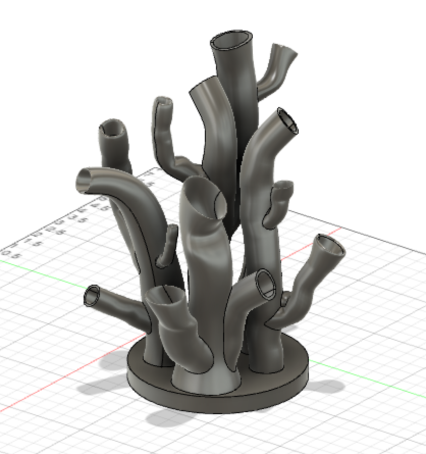
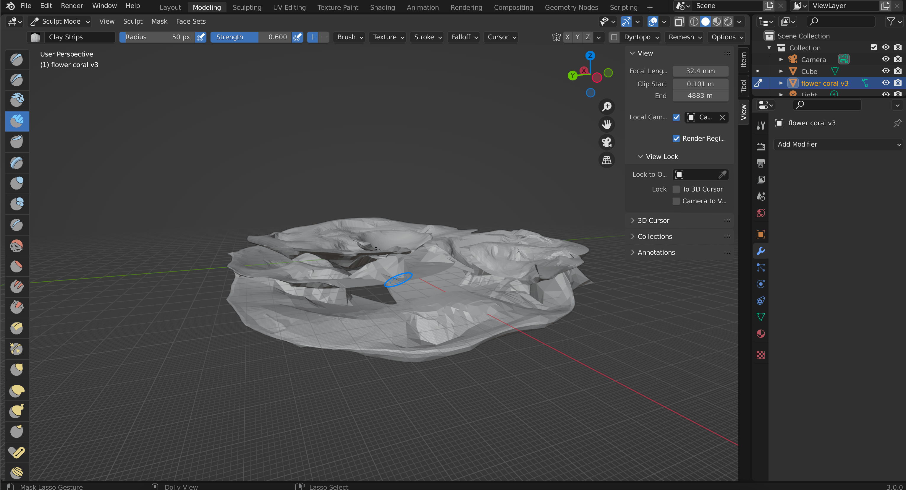
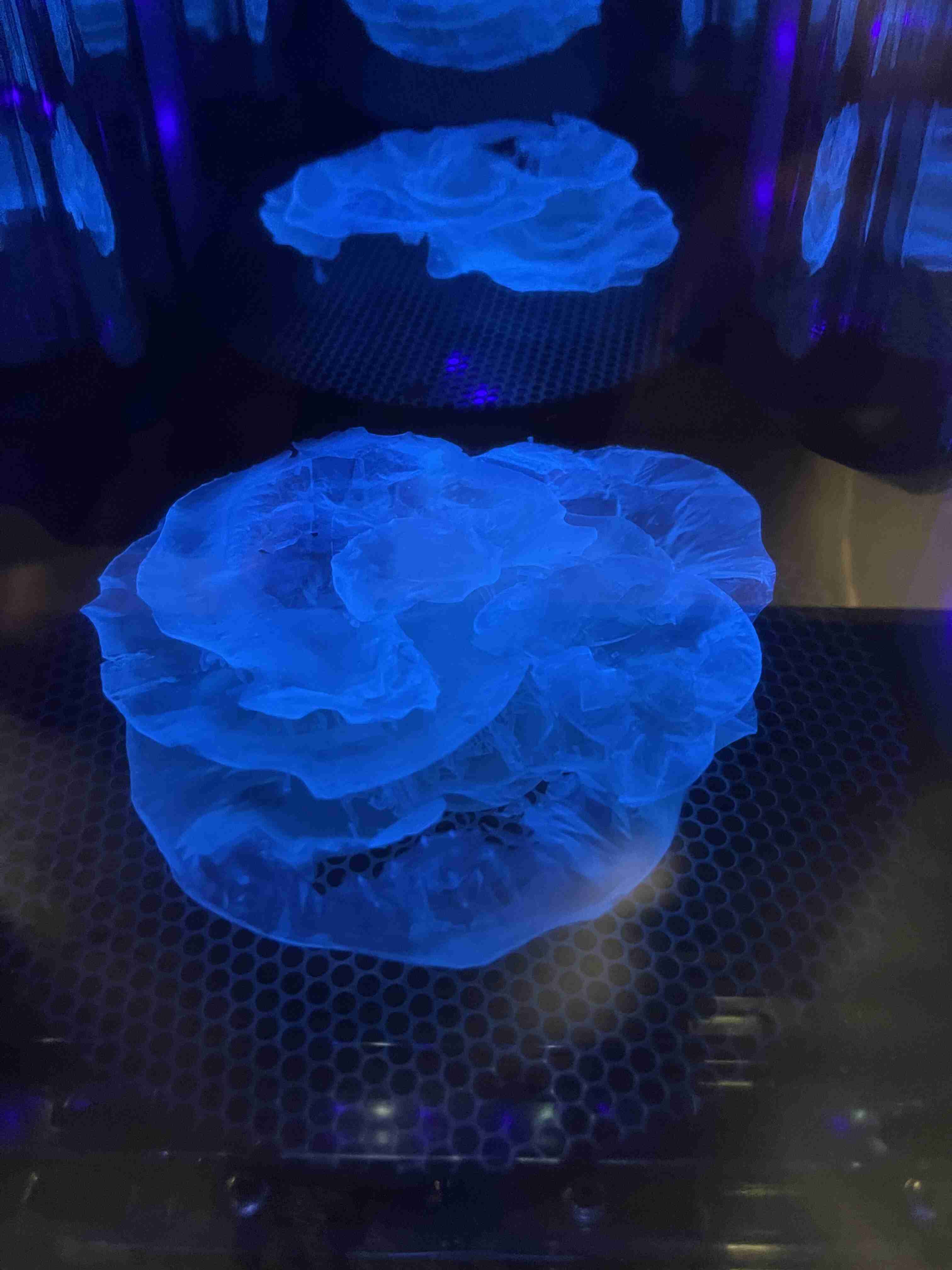
The last coral structure I created was inspired by table and flower coral.
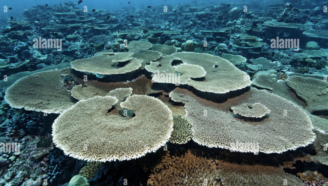
My approach here was:
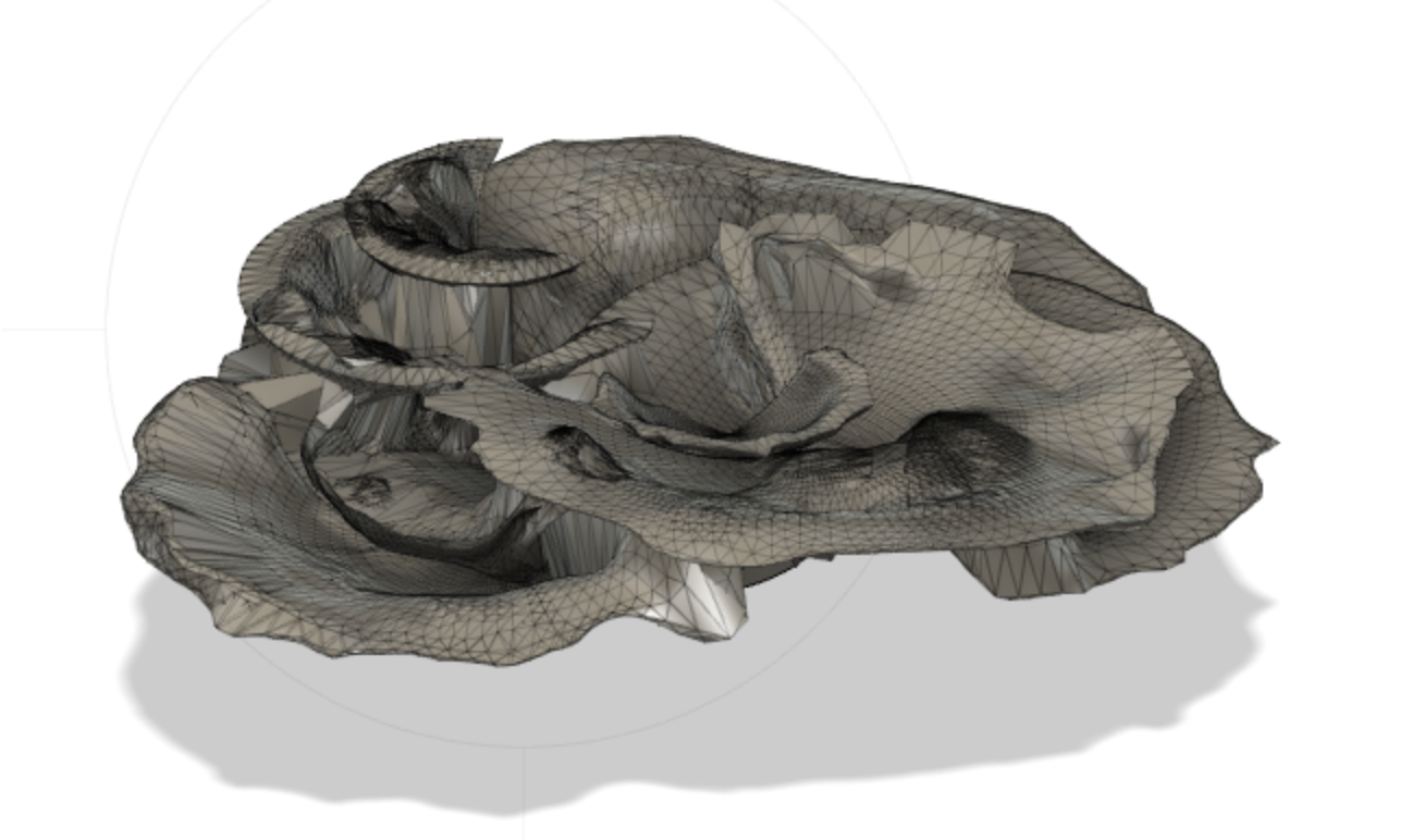
I ended up with something that looked like this:
The end result looked something like this:
I then tossed the STL back into Fusion to add a cylindrical base that would increase ease for mounting it.
Now that the designs were created, onto the Formlabs printing process!
I had decided early on that I would use Formlabs printers to create the coral structures. These printers use a stereolithography-based process to create models in a layer by layer fashion.
The only other thing I had printed using Formlabs was the housing I created for this miniproject , and the shapes were certainly NOT organic. I didn't quite know how the printer would respond, but I had seen other organic shapes online created using a Formlabs printer so I figured there was a good chance it would be fine.
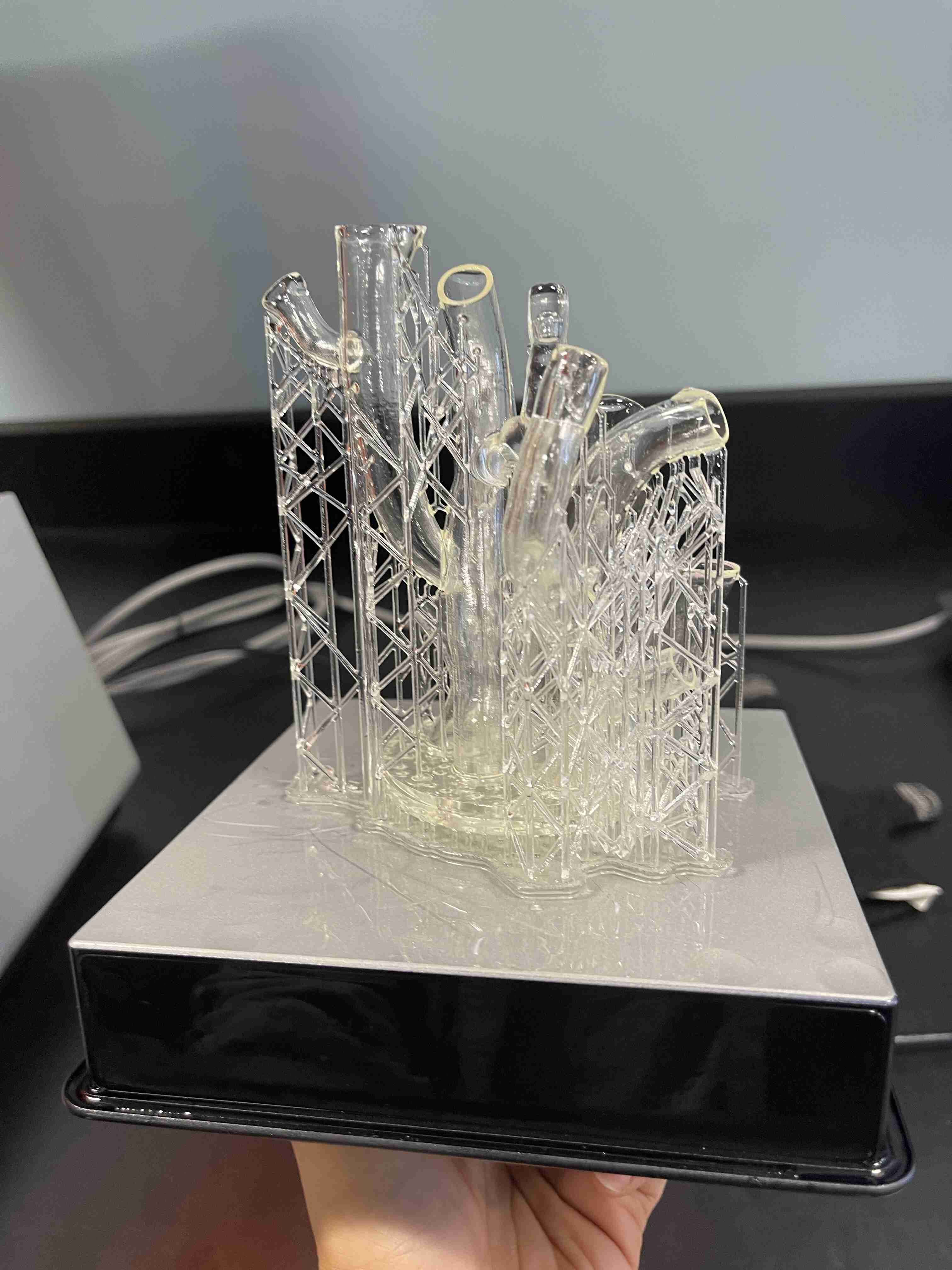
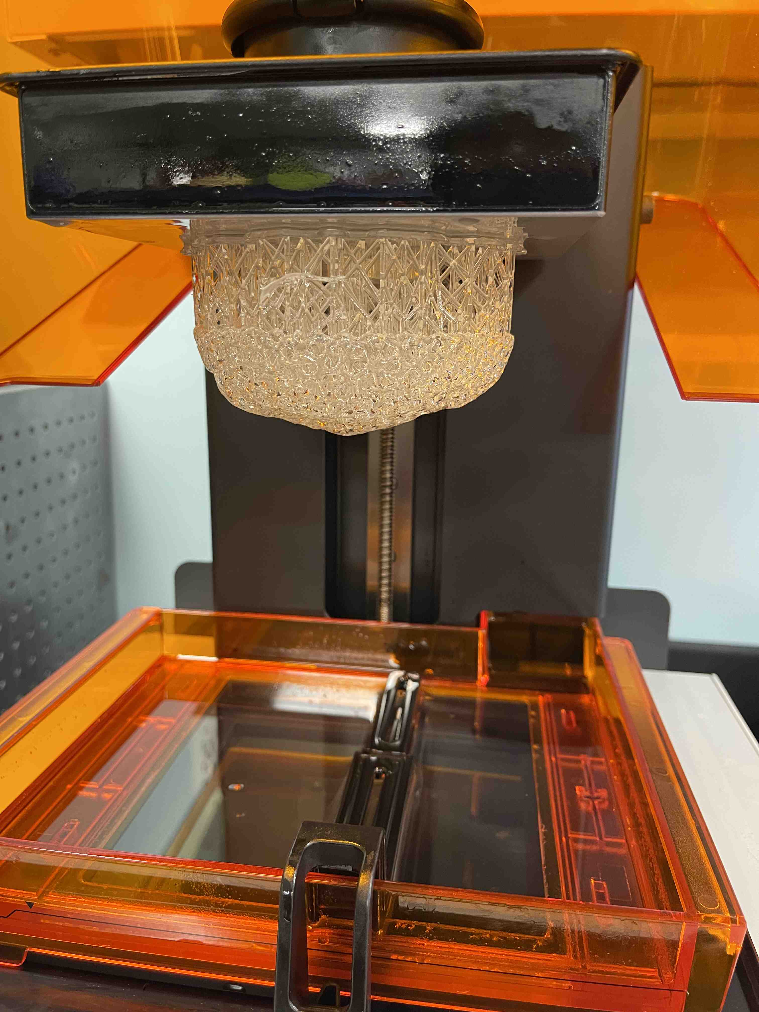
After positioning the object in PreForm, the Formlabs slicer, I had to scale down the models by roughly 50-60% for it to fit on the bed. Each of the mdoels took between 7-9 hours. The Formlabs printer I was using was a finicky Form 2 that my lab had almsot tossed because it wasn't quite registering the cartridge and tank. Probably not the best printer to hinge my final project on, but at this point I was committed and also low on time. However, this printer had successfully printed the lid in the above miniproject I linked, so I knew it was capable.
The first time I tried printing the coral, it failed about 15% way through the print. I found a thin layer of resin stuck to the print bed and a thin layer of cured resin floating in the tank.
My guess was the print hadn't adhered to the bed, and the piece floating in the resin had then blocked the laser from creating more layers, which led to the failure. Additionally, during the print, the printer also thought the cartridge had been removed but would re-recognize the cartridge a few minutes later, so these disruptions might've also caused the failure. I removed the resin stuck to the bed and made sure no residual chunks of resin floated in the tank. I also cleaned the sensor that recognized the cartridge and shoved the cartridge/tank in extra snugly before re-running the print. This time, the print was successful and I got a lil tube coral!
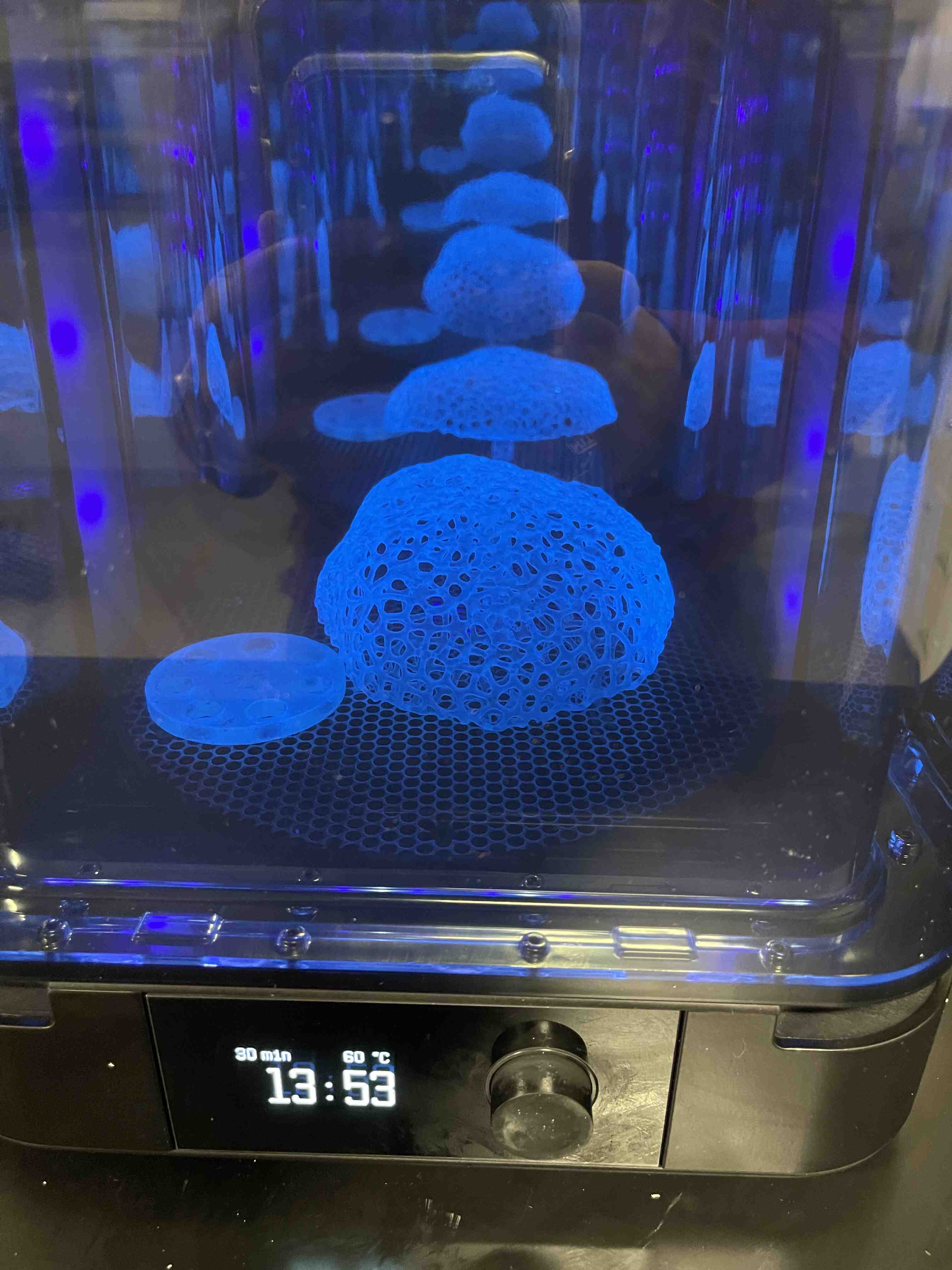
After printing with SLA, the parts require a bit of post-processing. Washing the models with isopropyl alcohol (IPA) to remove excess, sticky resin from the surface. Additionally, after the part is finished printing, the polymerization reaction may not yet be complete so it's essential to expose the part to UV rays and heat (such as sunlight) will ensure the material will perform as expected.
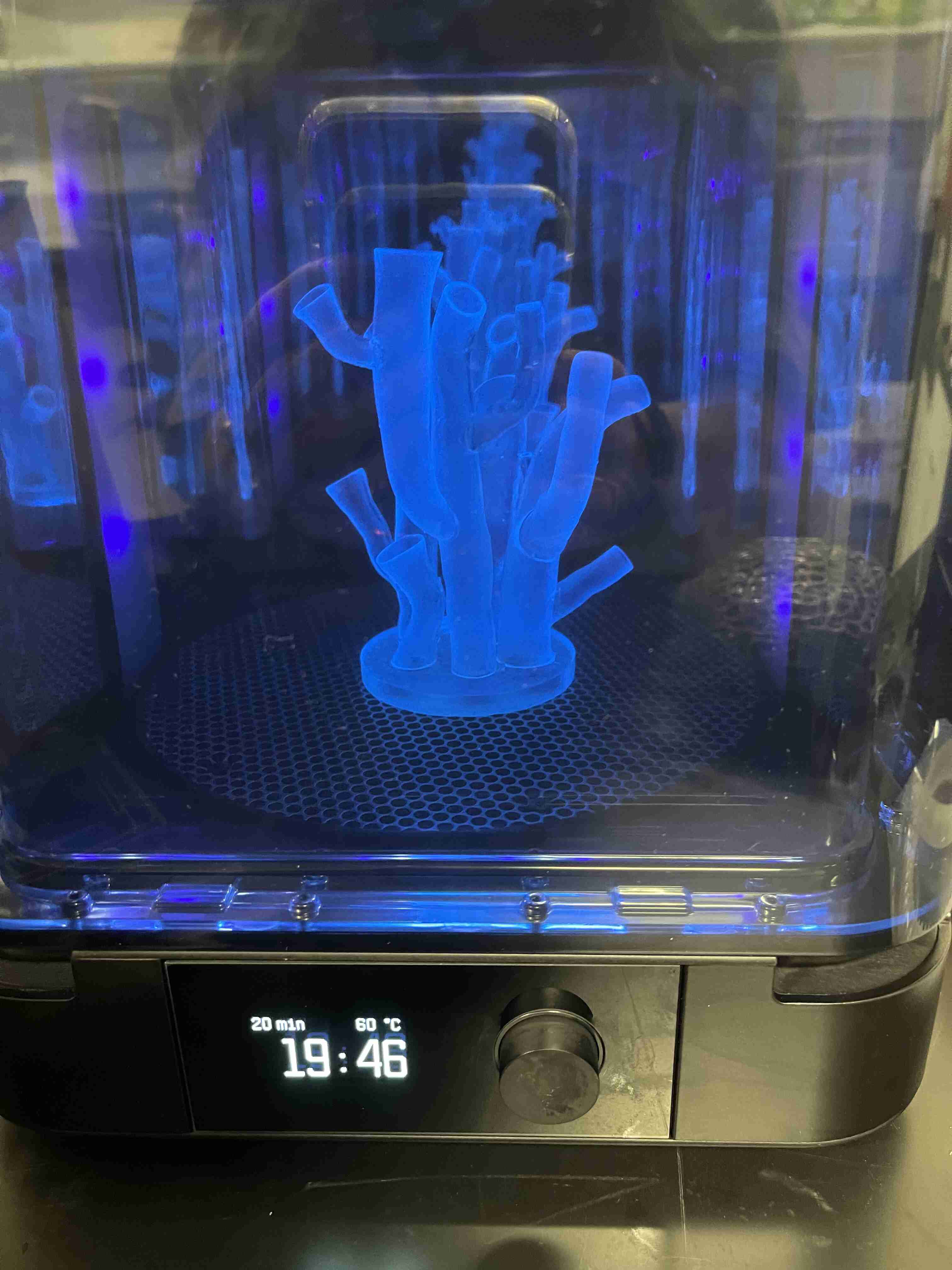
Thankfully, my UROP lab was also equipped with a Form Wash and Cure (I know, very fancy).
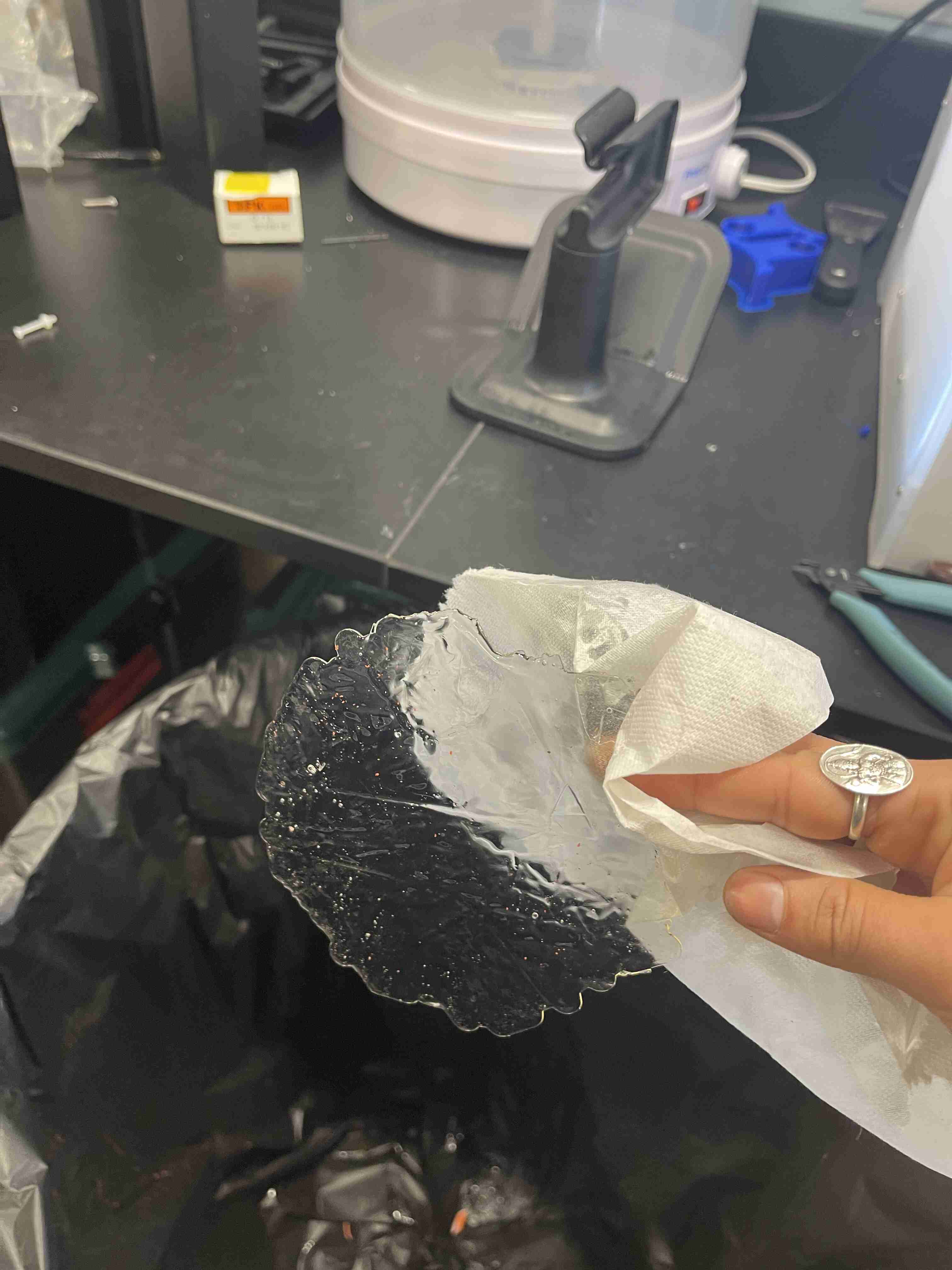
I removed it from the bed, and mistakenly started removing the structural support before washing it (I later learned you should remove them in between the wash and cure). I also definitely underestimated how long it would take to remove the structural support. After roughly 30 min-1 hour of meticulous clipping, I finally freed my coral and tossed it into the FormWash (which basically dunked my model in a few liters of IPA for 10 min).

After it was done, I made sure the surface was smooth before I cured it in the Form Cure.
This worked out super well, and I repeated it for the next three designs! However the whole process was honestly extremely time-consuming (from waiting for the prints to finish, and then performing the post processing steps). The printer also failed at least one time in between each successful print in a similar way that I decribed above. I could never quite figure out what was going wrong, but having to rely on a finicky printer was definitely a little stressful. Additionally, I initially wasn't careful enough when removing the supports and I poked a hole in the flower/table coral (the model was also wayyy too thin...I should've had the foresight to thicken the petals). I also snapped off the base of the Voronoi coral, but I was able to superglue the pieces back together after the pieces were cured.
While I printed the next two structures, I started working on designing the lamp base and designing the PCB.
I really struggled with designing a base. My primary issue was that I was trying to design two things at once: the lamp base and the electronics. It was almost a Catch-22: I needed to design the electronics to fit in the lamp base, but I didn't know if the electronics (especially the capacitive touch sensors) would work well through the resin, how well the LED's would fit, and how much space the wires and total electrical components would occupy. The lamp base was integral to human-lamp interaction and determined how I would need to design the electronics board. Additionally, given how important aesthetics and visual appearance was to the project, the base needed to not detract from the coral structure beauty.
Another issue was that I wasn't sure if each of the coral structures should live on separate bases and have separate electronic systems, or if they should live on one base and share an electrical system (so essentially three separate coral lamps instead of one). I had a vague idea of tying in some networking capabilities if they each operated using separate microcontrollers, but very predictably, I was havng trouble deciding what approach to commit to.
Now that I had placed myself in a pickle, I decided my first strategy would be to design the lamp base first, and then design the electronics around it. This was not the wisest idea I've had (in retrospect, I should've fully designed one working lamp starting with the elctronics, then the base) but I rolled with it.
Initially, I had planned on printing it from resin but I realized two things: 1) the bed was small and I needed to fit a PCB + other components within the base 2) resin printing is both costly and takes a long time. I CADed some prototypes
and sliced it in PreForm to get a time estimate. Even the smallest contained base took about 16 hours. I wasn't confident the print wouldn't fail. After ruling out resin printing as an option, I pivoted and started exploring different ways I could build a base. My base requiremments were that the base be opaque or clear to match the resin structures and be able to be diffused with light and that it was organically shaped.
There was also the possibility of molding and casting a lamp base, but the issues of this approach kind of overlapped with resin printing: time-consuming and constrained by the size of a 3D printer bed for mold creation.
I discussed various approaches with Anthony, and he suggested we could try melting an acrylic sheet with a heat gun and deform the heated sheet using pliers or other tools. I vageuly envisioned melting the sheet over crumpled aluminium and getting a clear, rocky looking base.
However, the reality was that heating the acrylic sheet took a long time. The acrylic would only heat up in a very small spot and would not deform well even when hot.
I poked around with this for an hour before I gave up.
I then realized I should focus on the electronics and get a system working before worrying about the lamp base. So I jumped to the PCB design before returning to building the lamp base.
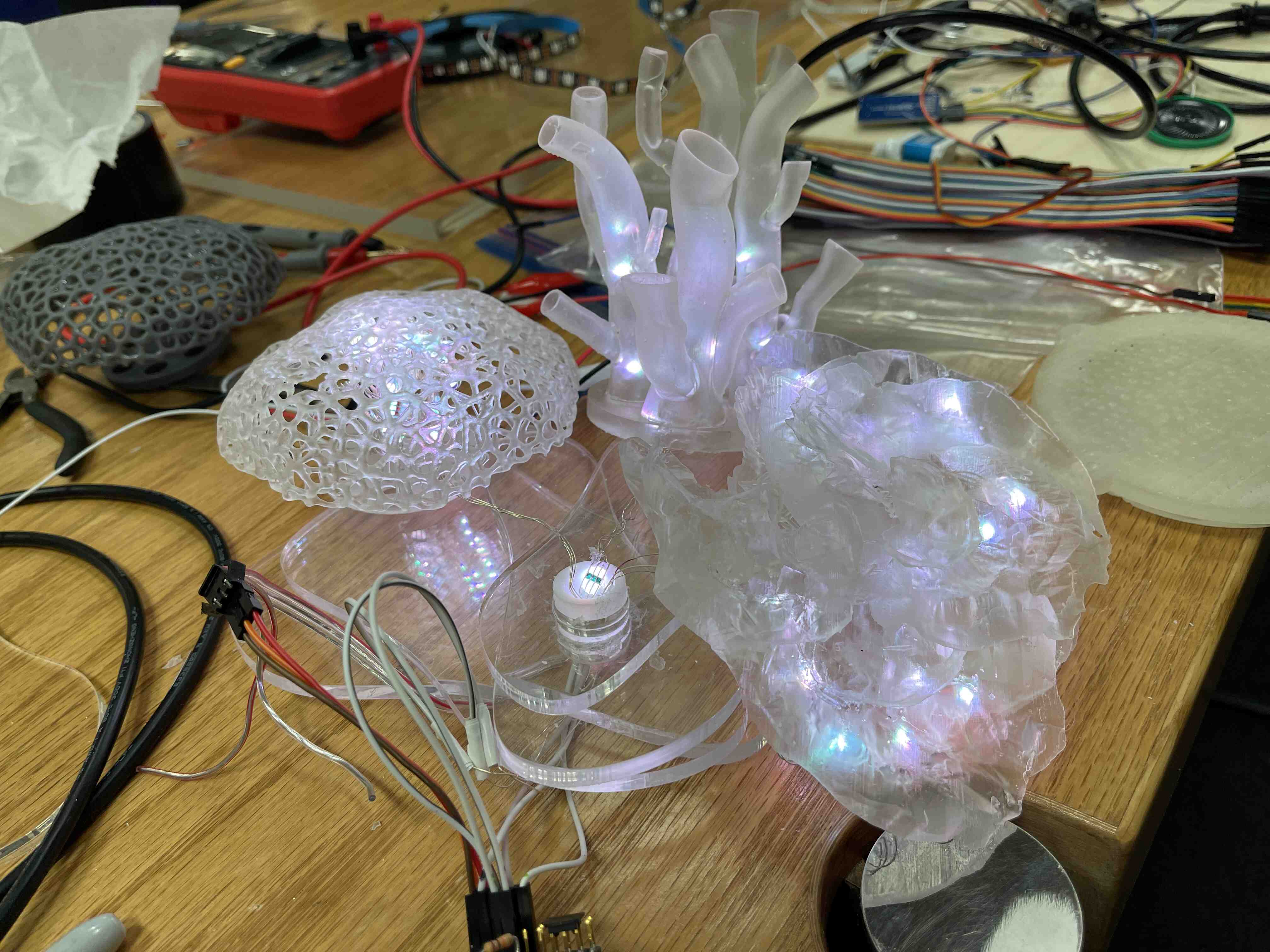
After I'd designed and soldered the PCB, I started thinking about the lamp base issue again. I wanted the base to be somehwat easy to hold so the lamp could be shaken and the accelerometer would have purpose. I happened upon an extra lid I'd printed as a test subject for my miniproject (linked above) before I;d printed the rest of the housing. Given that it was also made of clear resin, I wondered if I could embed the board in the lid and place on of the coral structures on top.
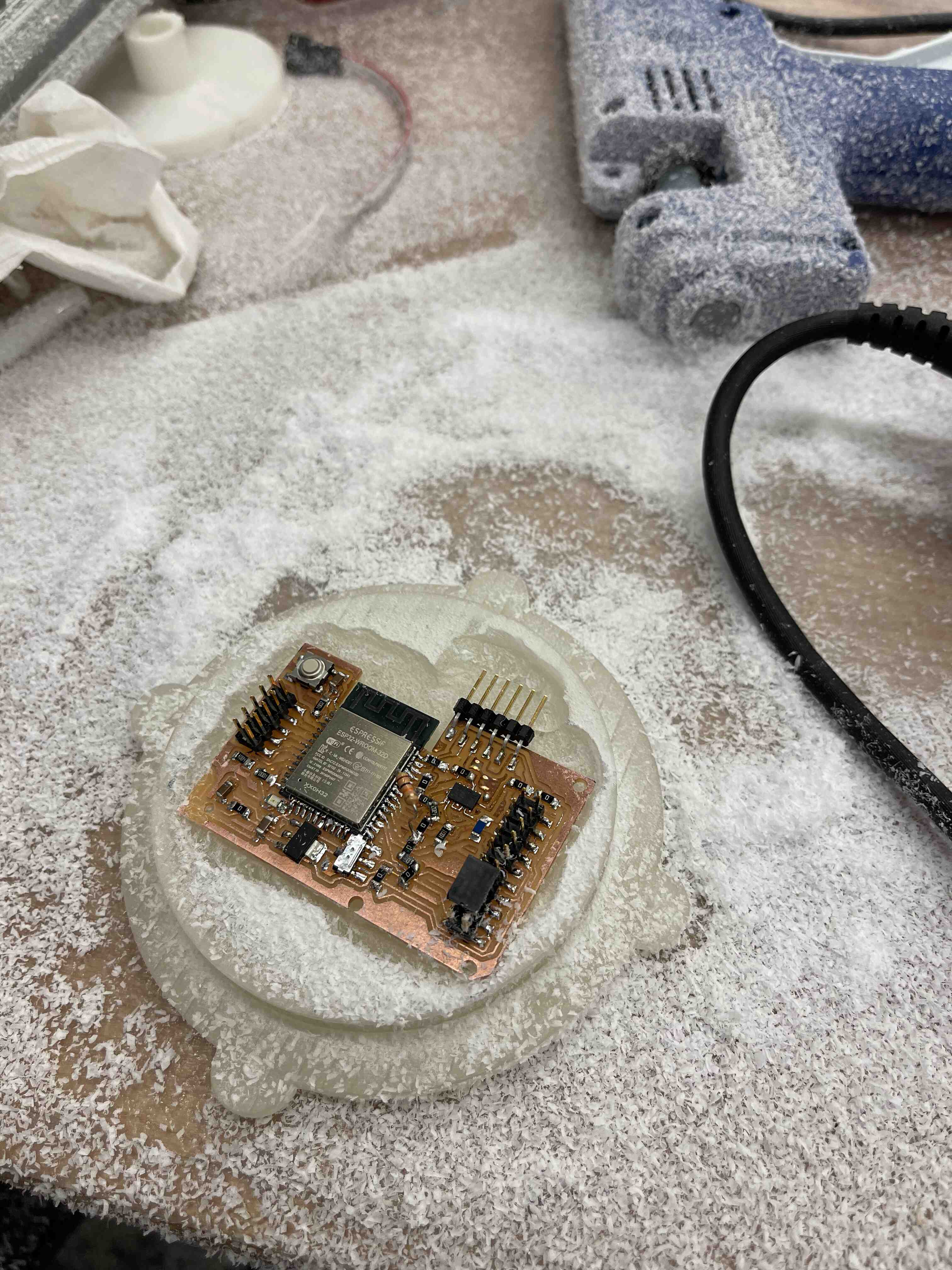
I sawed off the USB header to make the board shape easier to work with ( I could still get power from the programming header) and then tried milling away a board-shaped space on one side of the lid with the Dremel. It was the first time I'd actually used the Dremel, and it was super cool to use it on the resin (a bunch of white powder flew everywhere and looked like snow!). I eventually got a shape I was satisfied with, and thought it might work.
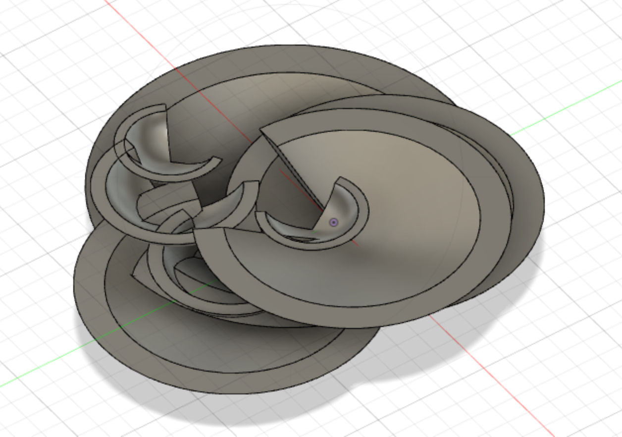
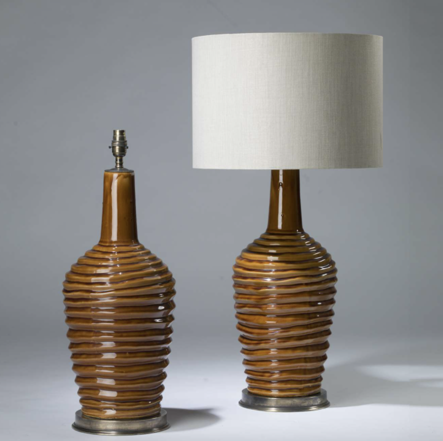
However, like the indecisive person I am, I then wanted a larger base because I decided to have all of the coral structures share the same base (this new decision was made becuase I'd realized I was running out of time and might not have time to mill and solder 2 more boards). I then turned back to perusing the internet for inspiration. I happened upon sliced structures such as these
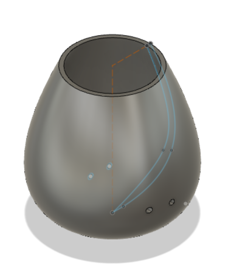
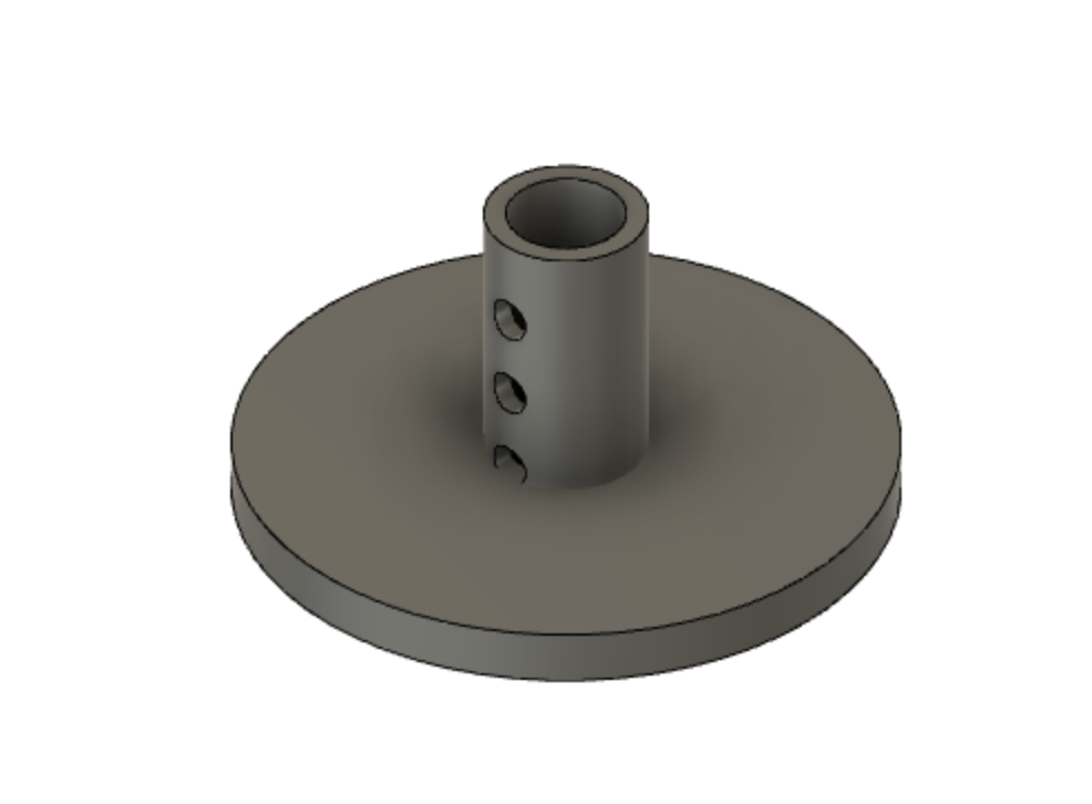
and realized I could create something like this out of acrylic. I quickly CADed a blob-like shape that vaguely resembled an avocado, lofted it in Fusion360 such that the top face was the same shape as the base but smaller. It looked like a weird wavy cone
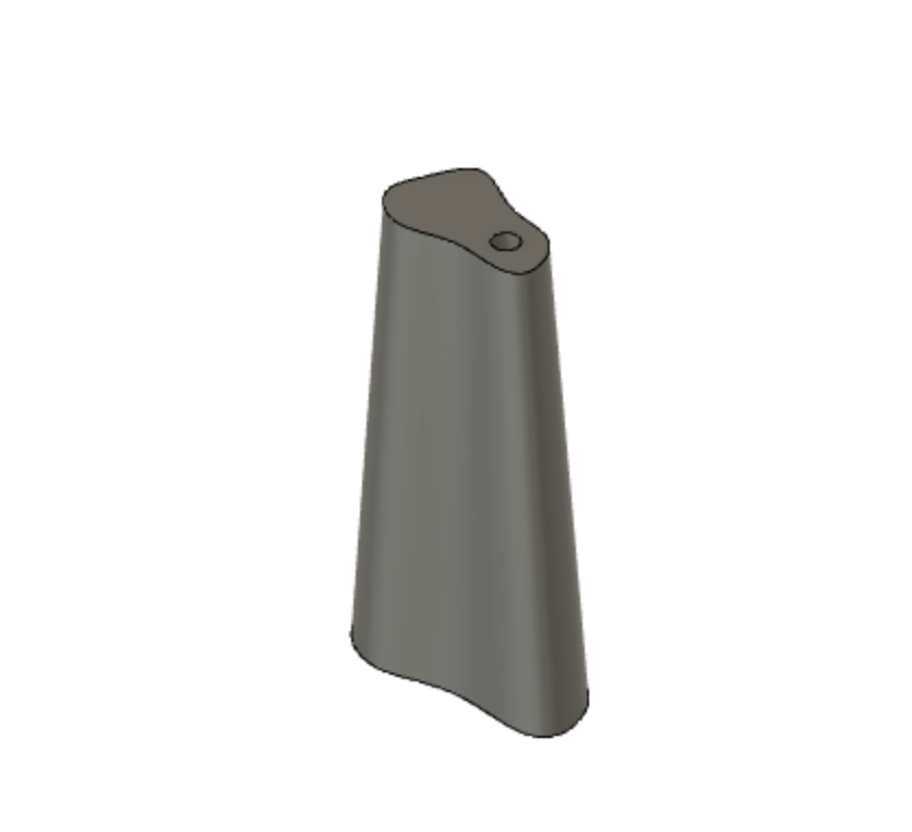
. I then extruded a hole in the center for a rod that the slices could spiral around. I also figured if I made the rod hollow, the wires could funnel through there. I then sliced the body into roughly 24 slices using offset planes and the 'Split' functionality and laid all of the slices flat.
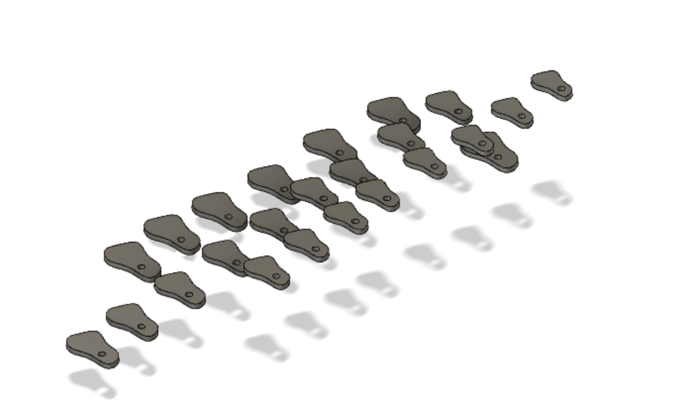
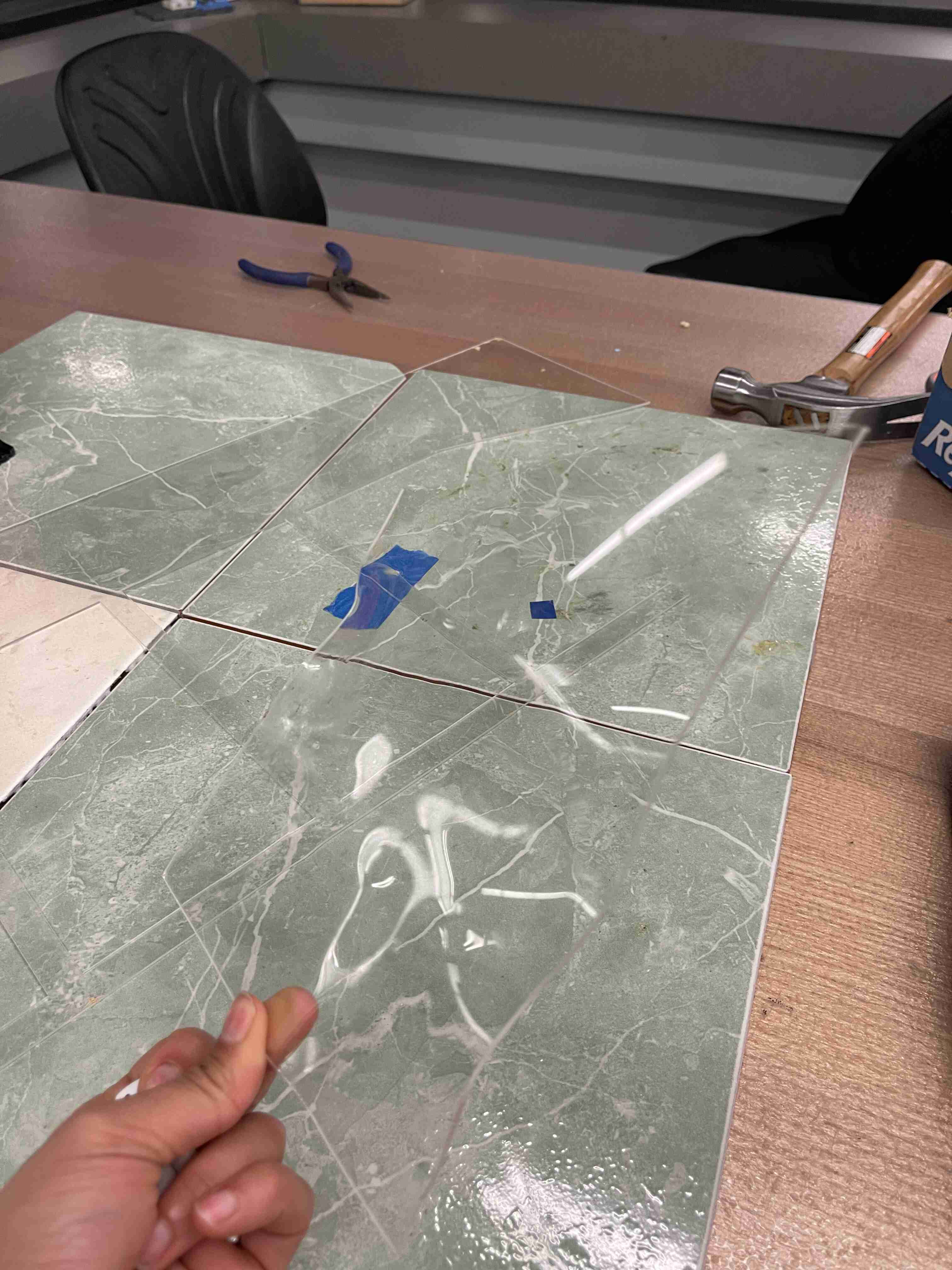
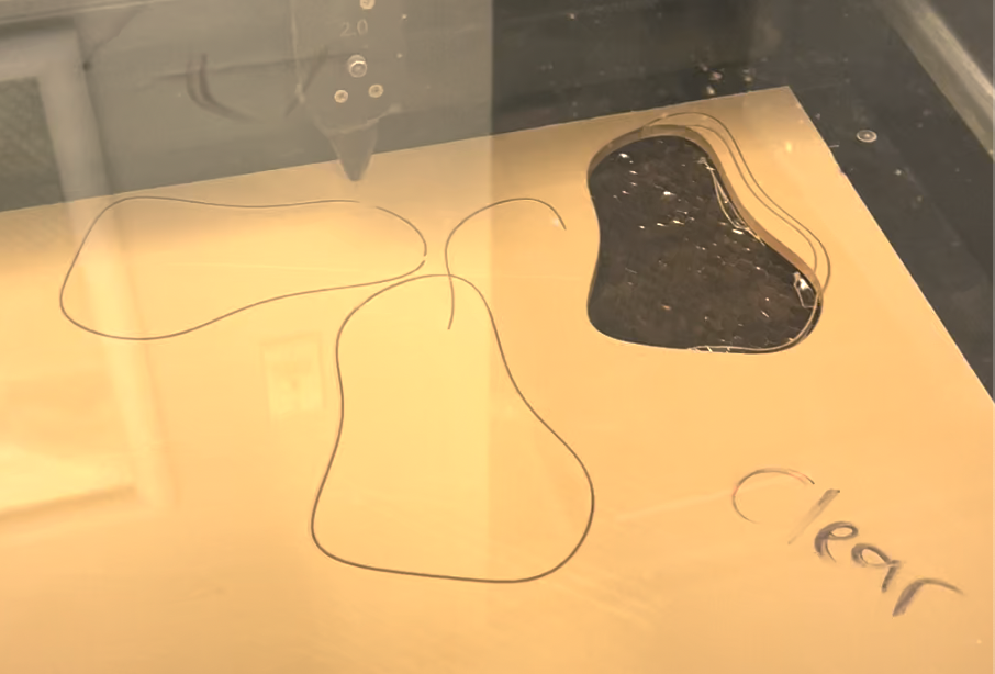
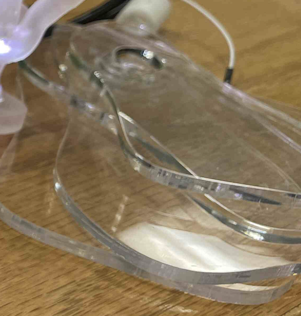
I then grabbed a clear acrylic sheet from EDS that was roughly a quarter inch thick, and lasercut my avocado-like shapes.
When I first came up with the concept, I wanted to have as many input devices as possible for the lamp. I considered sensors for temperature, humidity, vibration, touch, and shaking, and eventually narrowed these down to touch and shaking. The touch sensors would work by detecting a change in capacitance in a copper foil when touched, and the shaking would be measured by an accelerometer. I realized that having too many would 1) make the output of the lamp unpredicatble or make a certain outcome hard to replicate and 2) I didn't have a lot of time.
For output devices, I chose only LEDs. Since bleaching is a visual event, it made sense to stick to the visual domain intead of adding auditory output. I considered adding an OLED display to maybe display some data/or status on the the current 'state' of the lamp but it seemed unnecessary and might ruin the aesthetic. I also was having issues with deciding the shape of the lamp base so I didn't want to add anything more there than I had to.
In terms of a microcontroller, I chose the ESP-32 for several reasons. It had a large amount of pins, and since I didn't yet know how many capacitive touch sensors or groups of LEDs I would be lighting, I needed a microcontroller that could be flexible. I was also considering having different corals network with each other, and using that as another way to influence their mood (for example, if a coral registers another coral lamp in proximity or receives communication from one, then it would be happier/more resistant to experiencing a bleaching event). While I didn't get to implement this, I definitely didn't regret my choice of microcontroller.
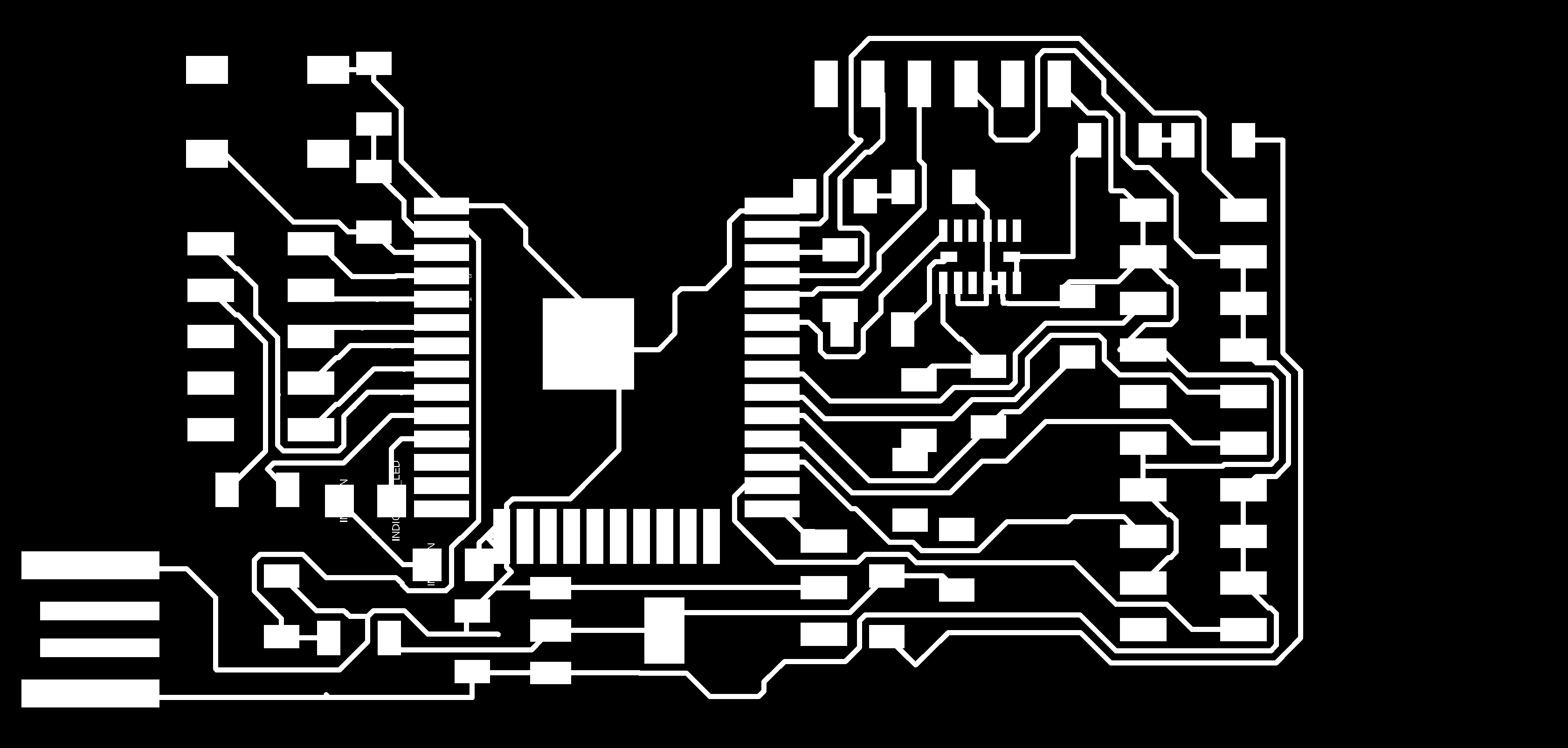
For the PCB design, I chose to use Eagle in Fusion. It was great being able to use one software for the majority of the design work. Like I mentioned before, since I didn't quite know how many separate sensor clusters + LED clusters I would need, I dedicated 6 inputs for capacitive touch and 6 output pins for LEDs.
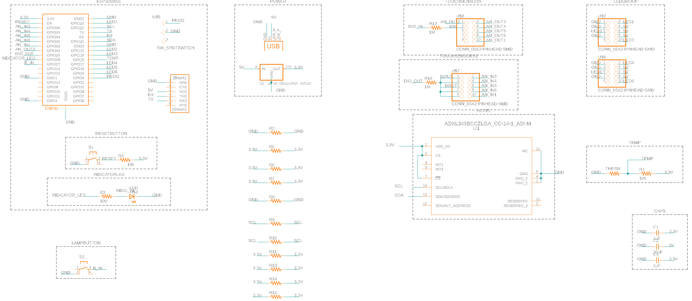
Routing the traces was more than a little annoying as usual, especially because I tried to take into account that the ADC2 pins didn't work when WiFi was turned on (not yet sure if I needed WiFi capabilities yet, but better to keep the options open).
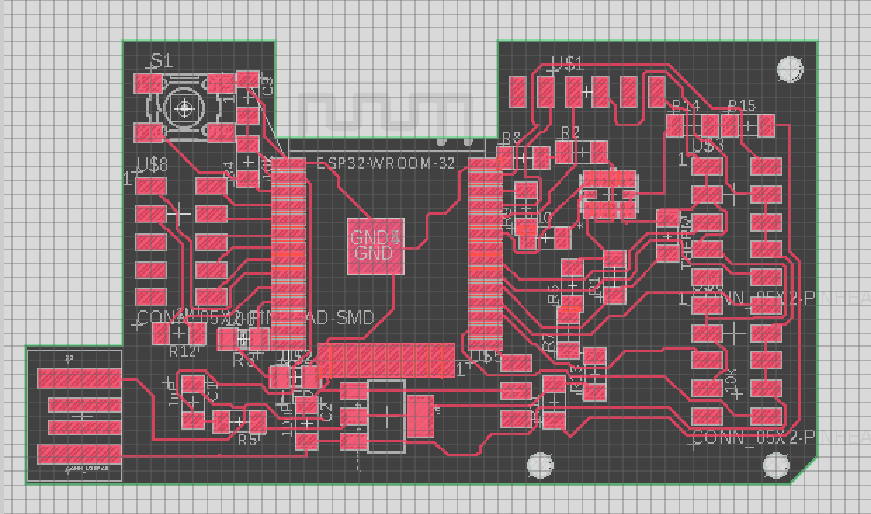

I ran into a few issues.
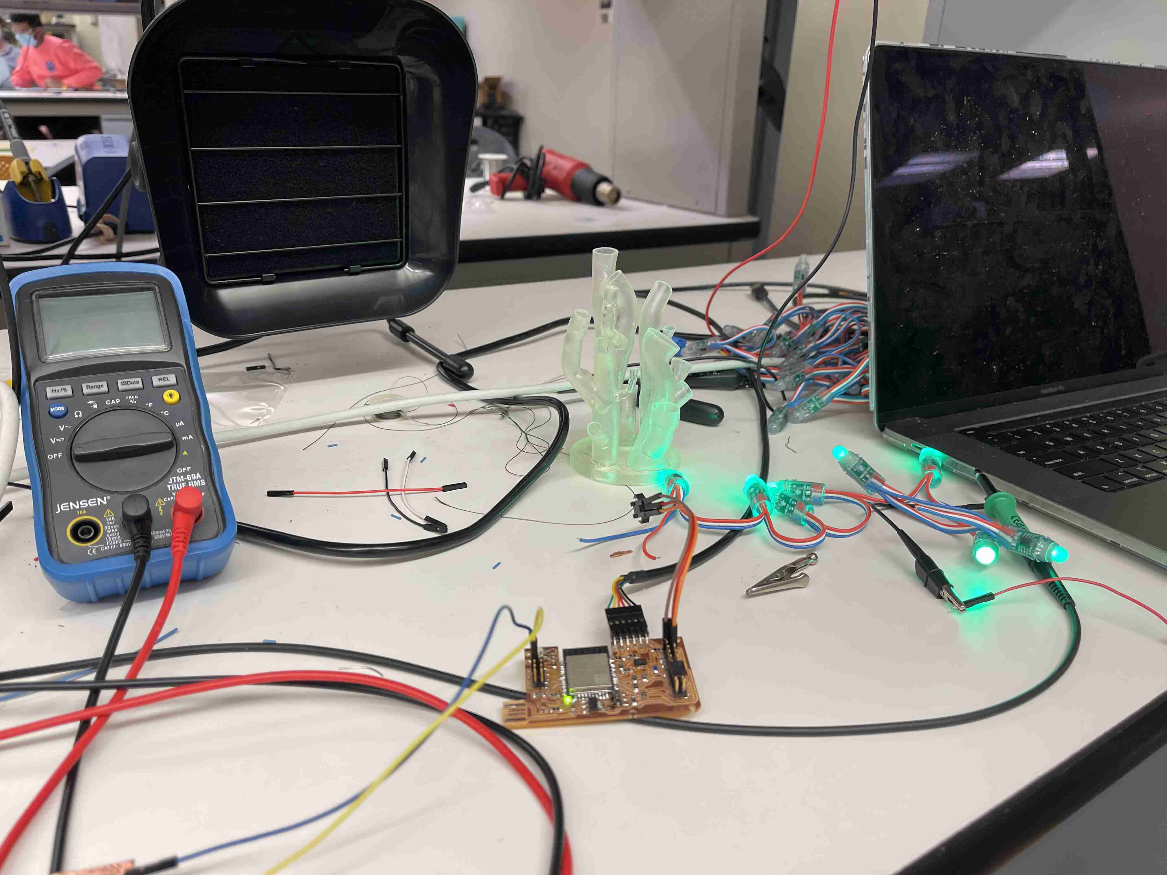
In the end, however, I was able to get the capacitive touch pins, the accelerometer, and the LED pins up and running!
One of the biggest issues with my changing lamp design was my choice in LEDs. Initially, I had gotten these globe shaped LEDs, but the wires were just way too bulky, and didn't fit well with the base or the flower shaped coral.
I had bought another LED strip, only to find that it had 5 wires (3 Signals,Power,GND) and wasn't easily compatible with the board I had milled (designed for Power, GND, and LED Signal). Anthony didn't have another LED strip on hand, but he did have an array of Neopixels on a sheet. I started the painful process of desoldering them from a sheet
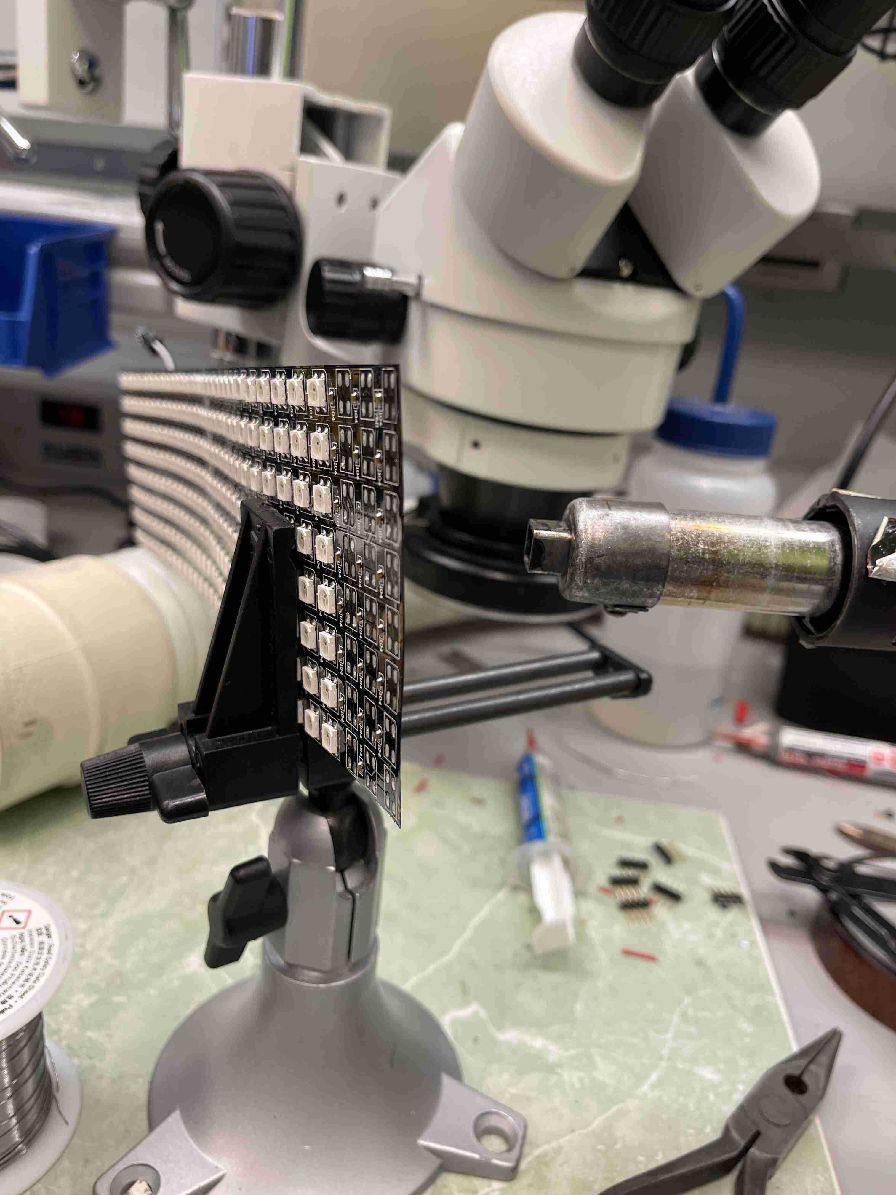
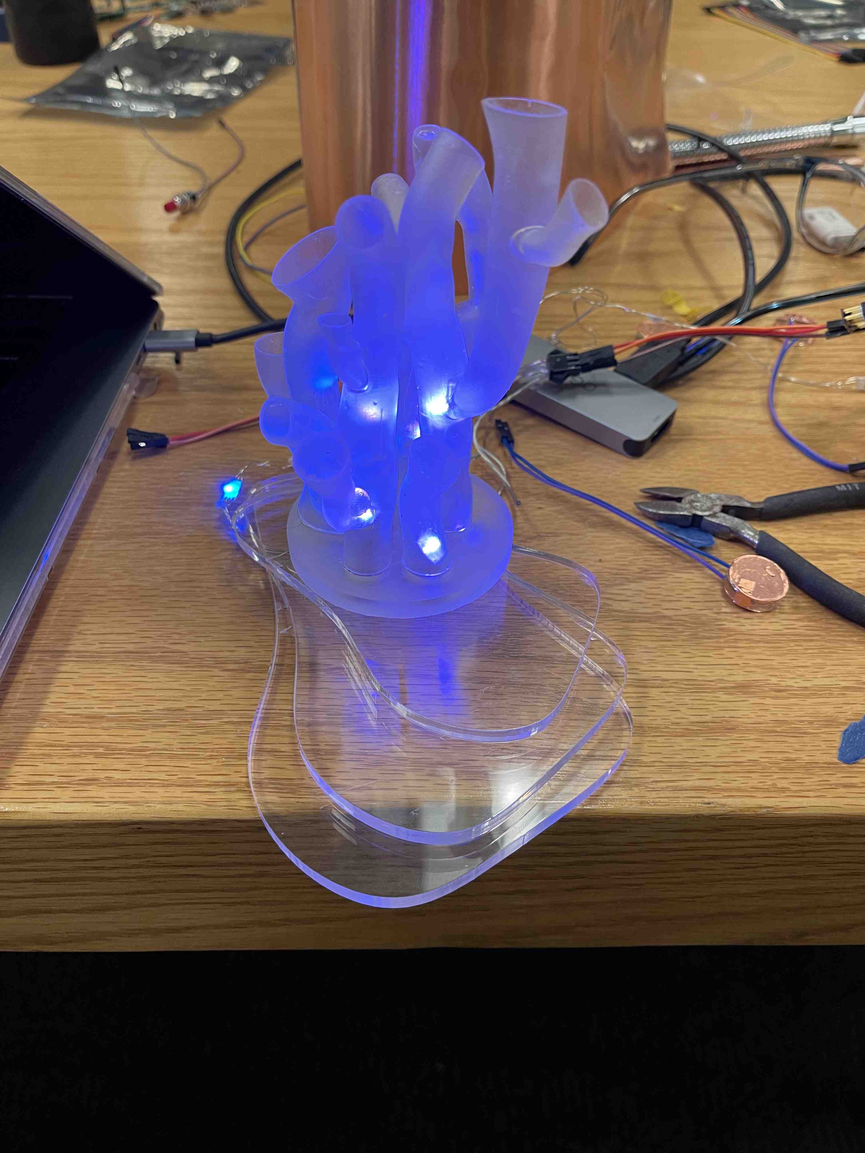
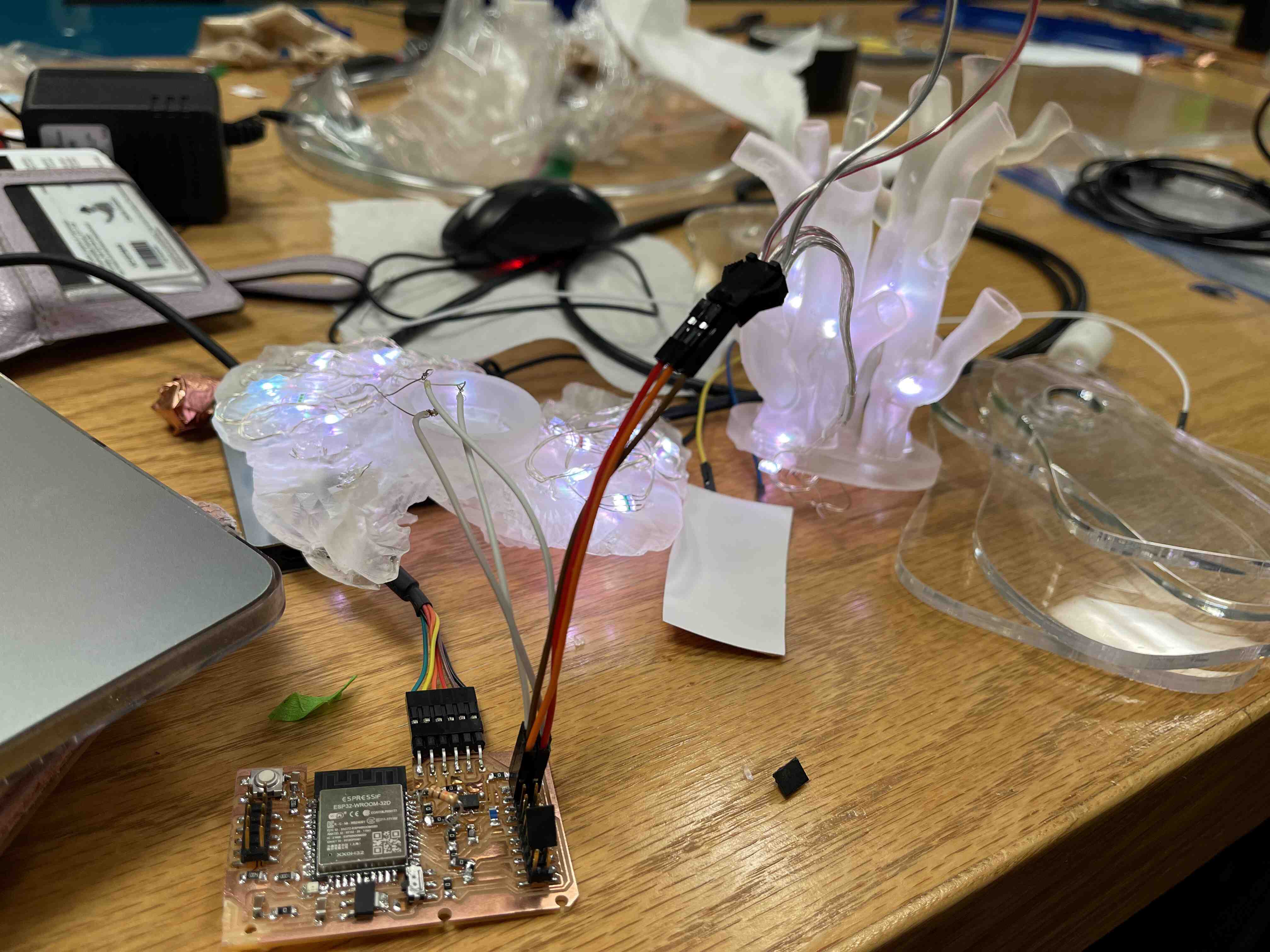
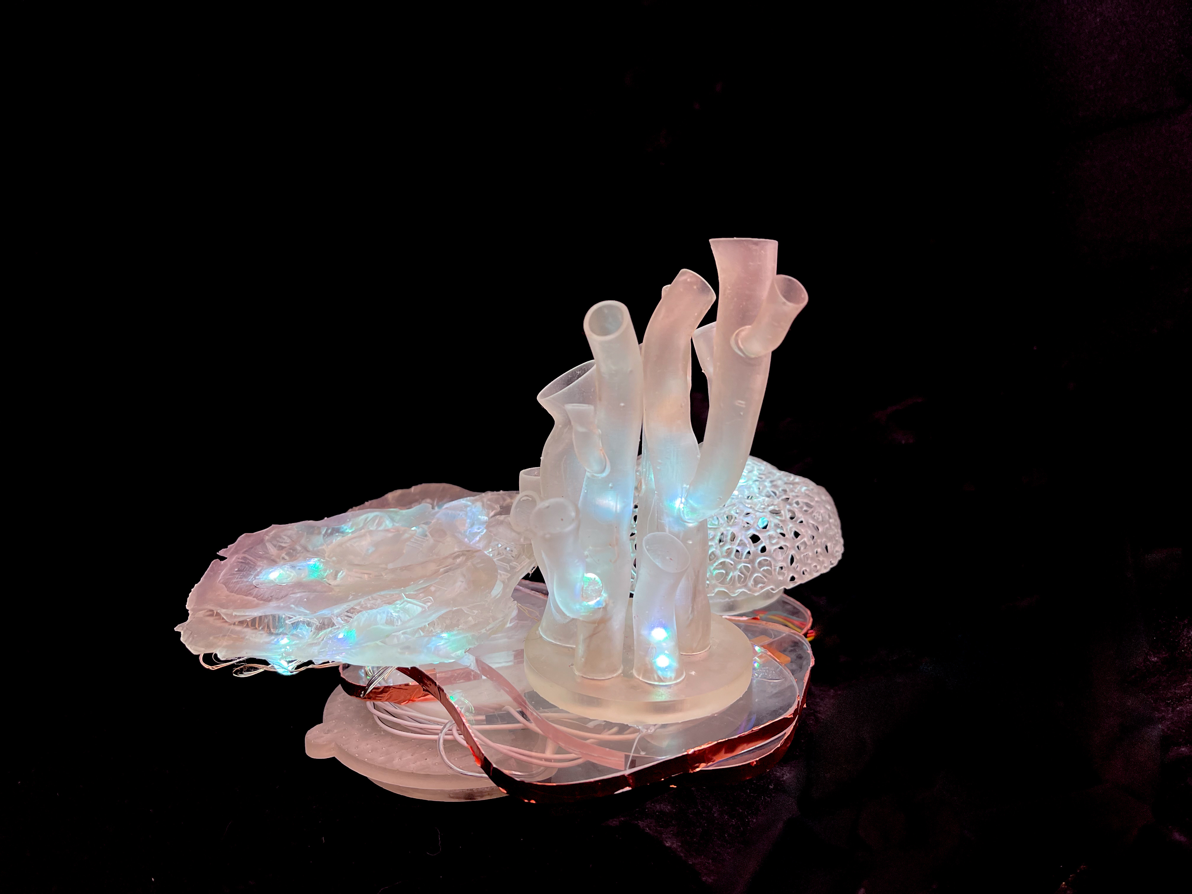
and was intent on wiring them together individually (AHH) but major shoutout to Katherine Xiong for giving the addressable LED Fairy Lights that she didn't use! While I discovered that the LEDs don't diffuse super well, the flexibility of the fairy lights were perfect for the weird forms in my project.
I placed copper foil along the edges of the base to act as the capacitive touch sensors. I stacked the lamp onto the previously-milled resin lid for some extra height, and wrapped the wires around it such that they couldn't be seen from above. I then hot glued everything together and decided I could stick the board underneath the base and hide it under one of the coral structures as an anti-climactic end to the lamp base integration question.
For the code, I decided to implement the functionality in a state machine. Essentially, the lamp had 3 main states: Happy, Annoyed, Unhappy. The state the lamp was in was determined by an 'unhappy' variable, which tallied the amount of times the lamp had been 'disturbed'. The unhappy counter incremented when the lamp detected it had been touched (capacitive readings dropped below a value) or it had been shaken (the accelerometer readings were above a certain value). I also incorporated the level of disturbance for capactive touch (if the reading was very low, I incremented the 'unhappy' variable by a higher amount). The accelerometer had been on the fritz while I was testing (it would think it was being shaken when it wasn't), so I gave it a more minor role than I would've liked, and only had the readings impact the unhappy variable in a limited capacity.
I used these images for the 'Annoyed' and 'Bleached' states.
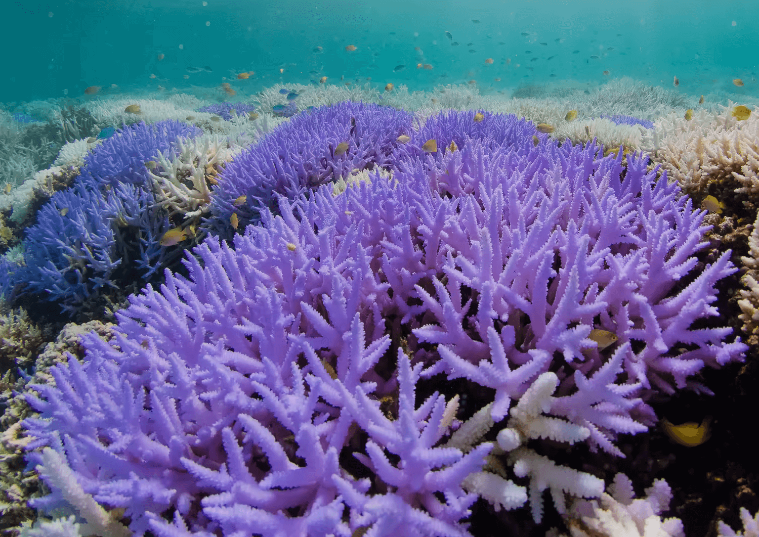
I wanted to use a healthy coral reef image for the 'Happy' state, but it wasn't saturated enough so I used a Rainbow palette instead. Additionally, the LEDs were having toruble cycling through the colors while in the state machine, and would remain static instead. I tried fixing the code such that they the palette would only be called once per state, but there must be some delay or something else interfering with the cycling effect because it didn't fix the issue. Either way, it was still fun to experiment with!
The code worked overall. I realized the capacitive baseline readings changed in each setting and were also affected by my laptop being plugged into a charger while it was powering the lamp (this happened during the demo and I didn't realize that was what was interfering with the lamp). If I'd had more time, I would've incorporated the rate of change of sensor readings rather than the raw values to avoid this issue.
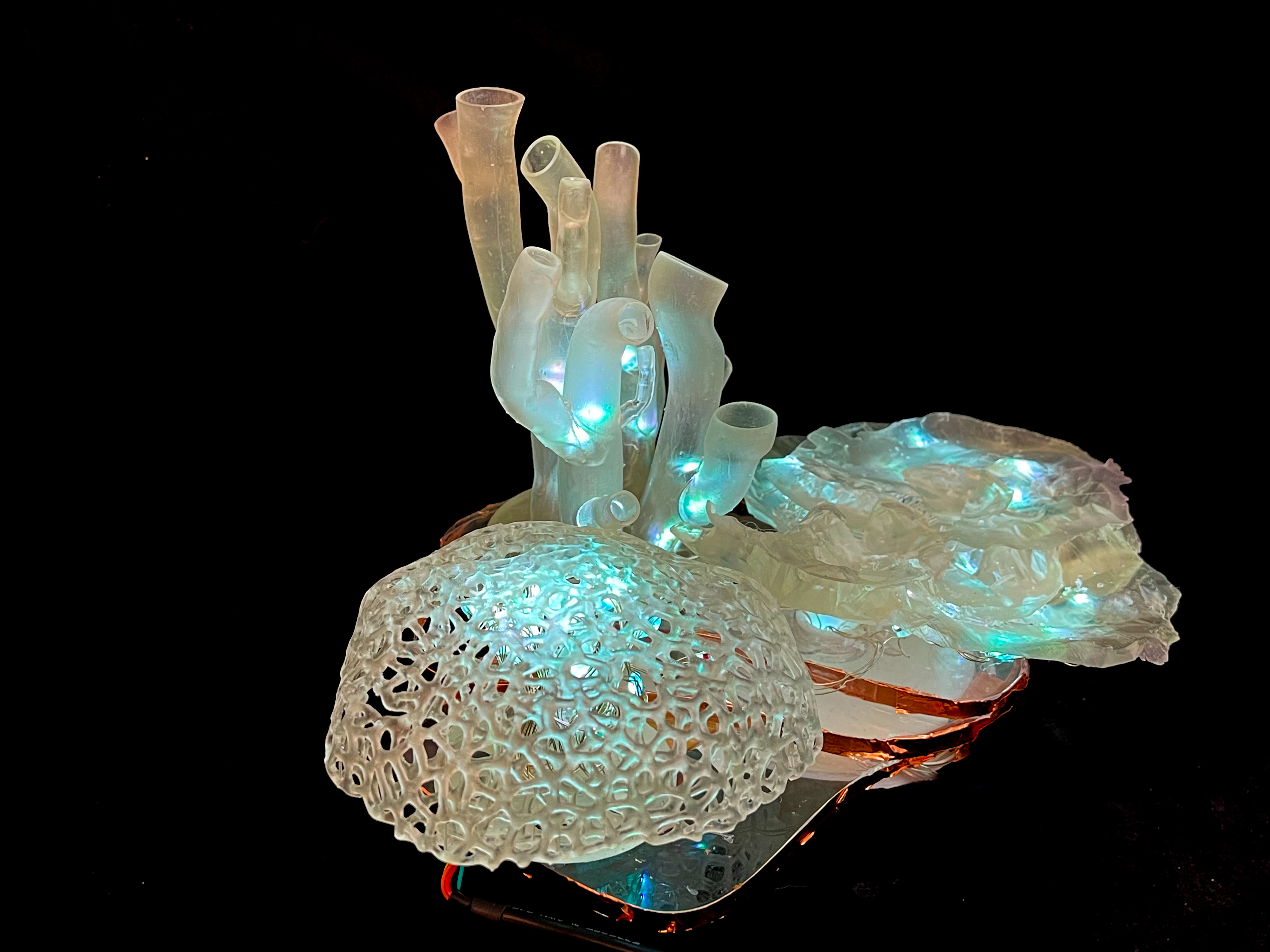
Overall, I created a coral lamp capable of responding to human disturbances! As far as I know, a lamp like this hasn't been made before. While I would evaluate the project as a success because the system did perform as intended, I think I could've iterated on the sensor code so the system was less finicky. There's still a lot of room for improvement, but I gained an immense amount of CAD skills during this project. I'm also way more conscious of how much effort system integration takes. In the future, it would definitely be cool to improve on this protytpe and build a modular coral reef lamp system!
Thank you to all of the HTMaA course staff for the support and dedication throughout the semester! I wanted to specifically give a huge shoutout to Anthony, who was an absolute godsend in this class. Best TA ever. <3