
Computer Controlled Cutting
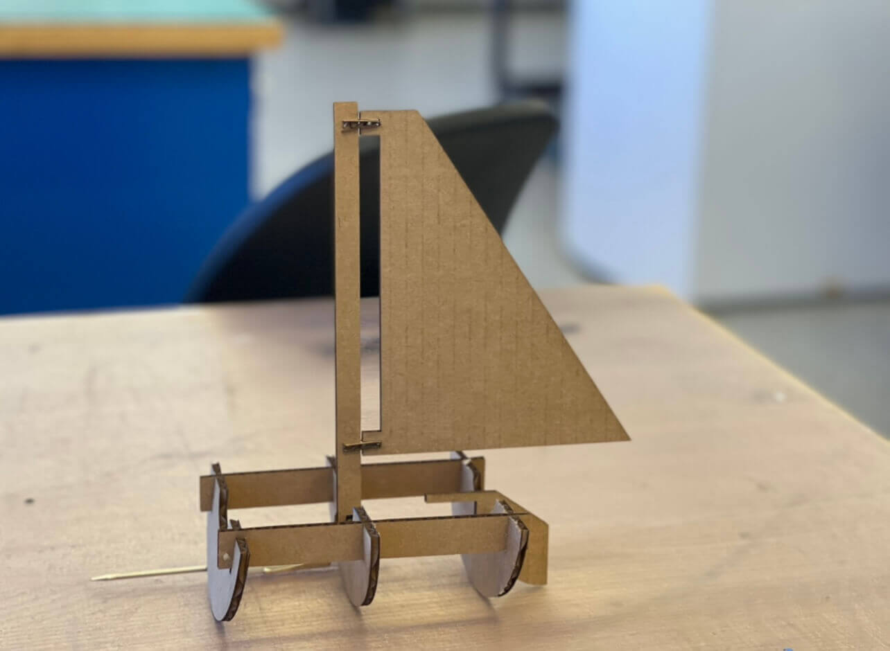
This week's assignment was to cut something on the vinylcutter, and then design, lasercut, and document a parametric construction kit that can be assembled in multiple ways. I chose to try to make a sailboat.
When I started, I think I hadn't quite understood the concept of a parametric construction kit, and just tried to design pieces that could be press-fit into the shape of a boat with certain pieces being interchangeable. If I'd given it more thought, I would've designed more pieces to fit together in multiple ways, rather than just having the components fit together in one specific way.
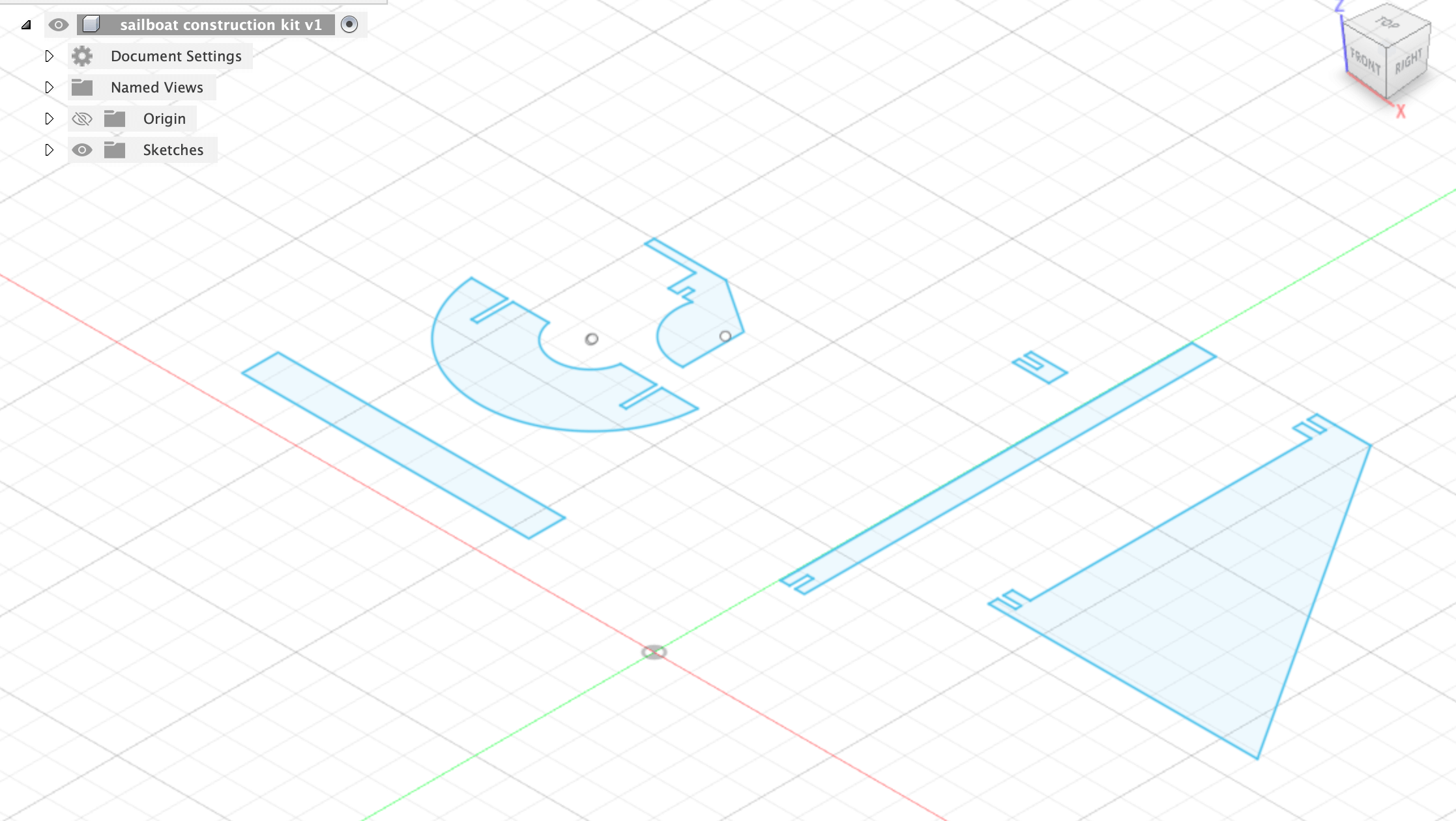
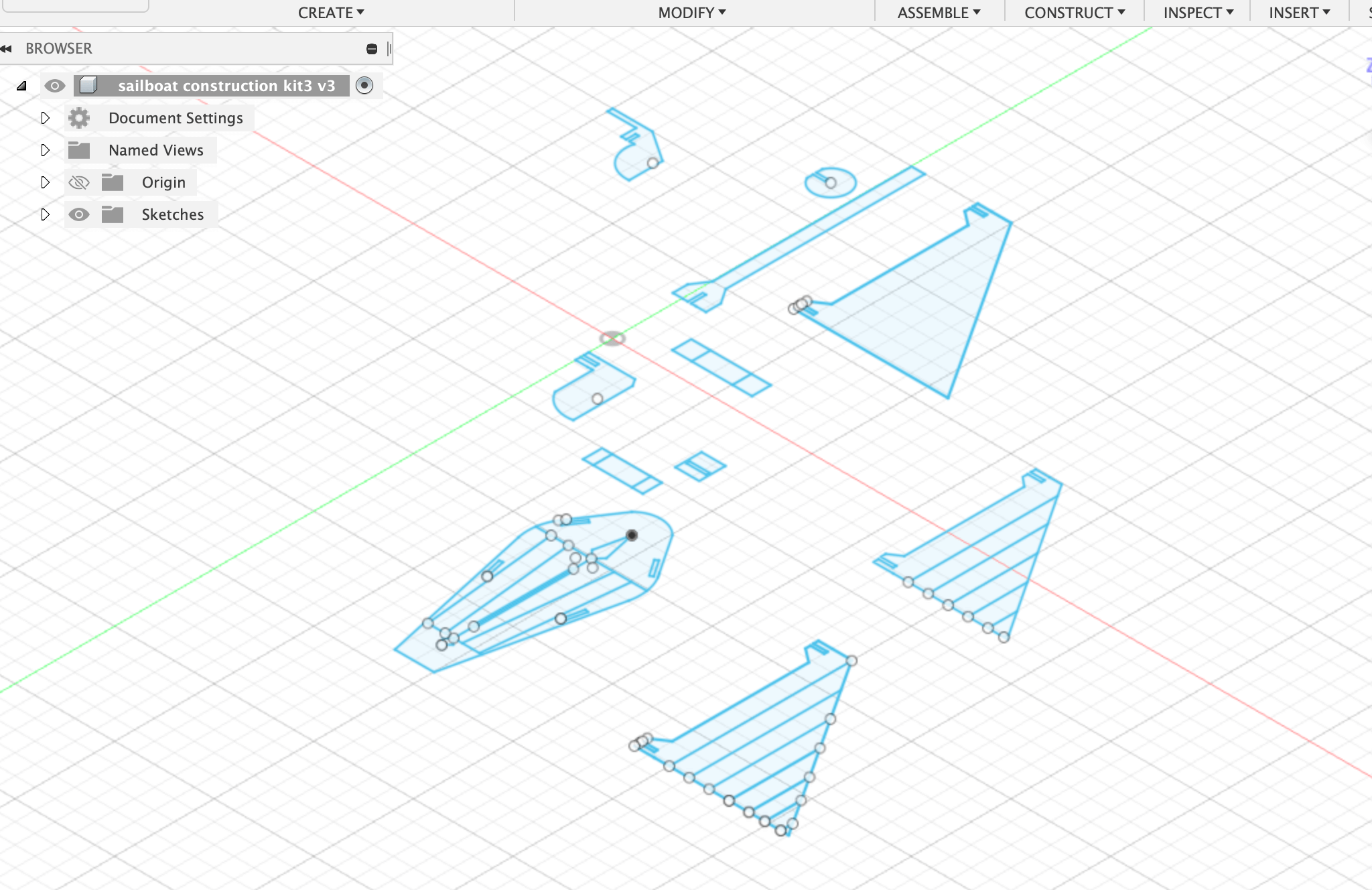
In Fusion 360, I was able to use the 'User Parameters' functionality to quickly define the size of the pieces. I also set all of the joint clearances to roughly .17 inches or around 4.1mm, and added .06mm to account for the lasercutter kerf. I created each component as a sketch, and then exported them as dxf files to Adobe Illustrator where I was able to modify line color/width before preparing them in svg format.
I also hadn't used Illustrator before, so one thing I almost got tripped up on was ensuring everything was in the same units (I opened the files in points, millimeters, and other units before actually finding the setting for 1:1 in inches)
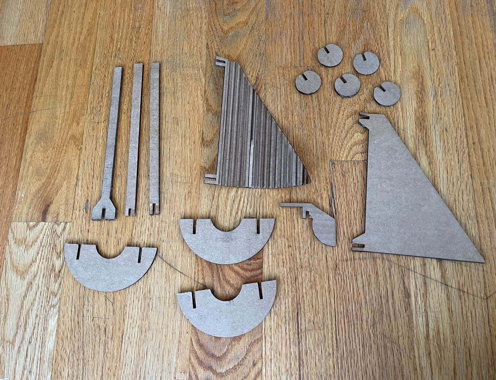
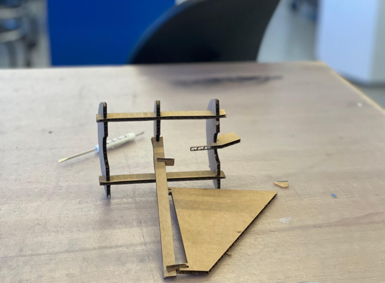
I'm not super experienced in CAD, but one approach that may have helped me was to assemble it in CAD first instead of laser cutting and prototyping based on outcome. I needed to print certain components several times as I iterated, one example being the sail pins (the joints were too shallow the first time, so I increased the depth and made the shape circular). However, I was super happy I defined all of the parameters beforehand, because they helped me iterate faster.
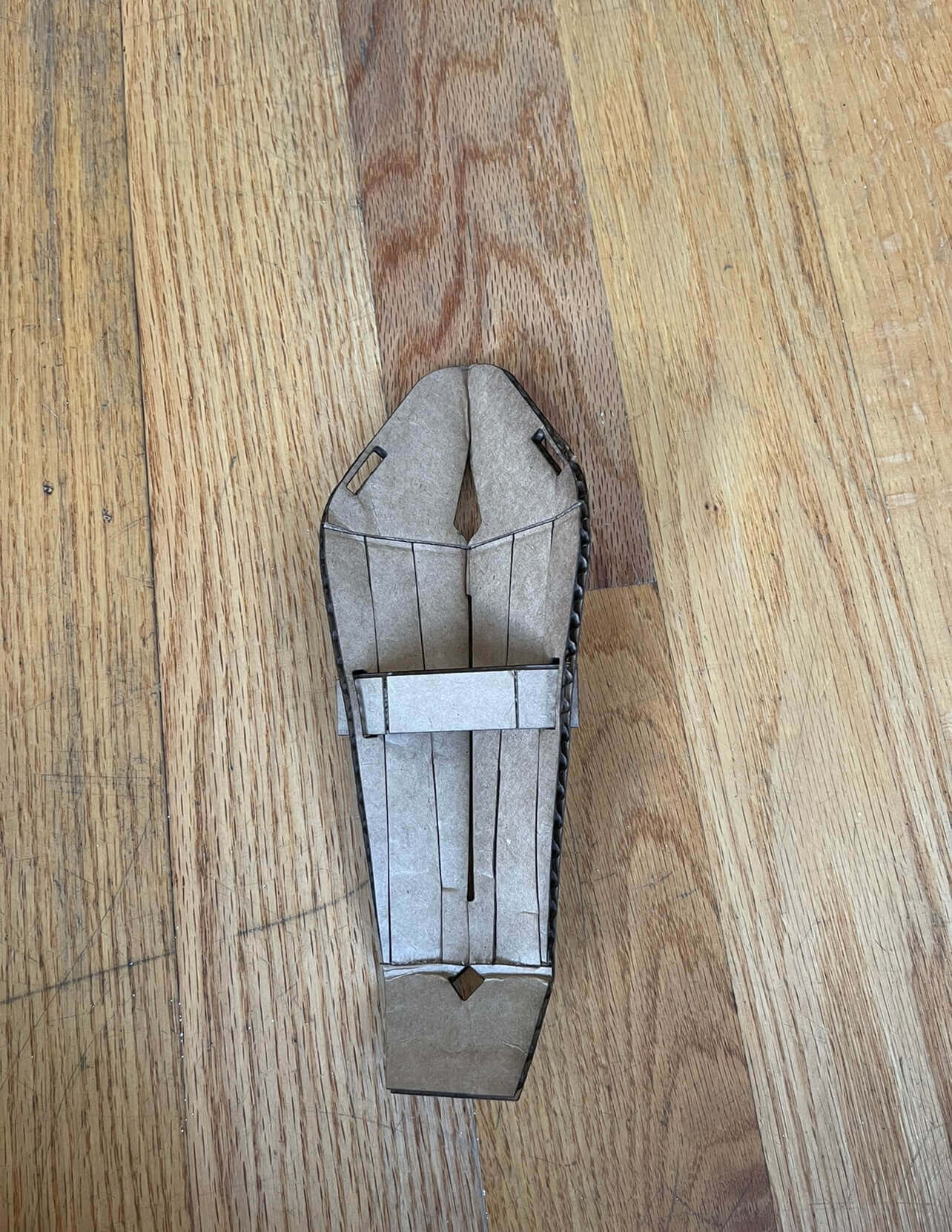
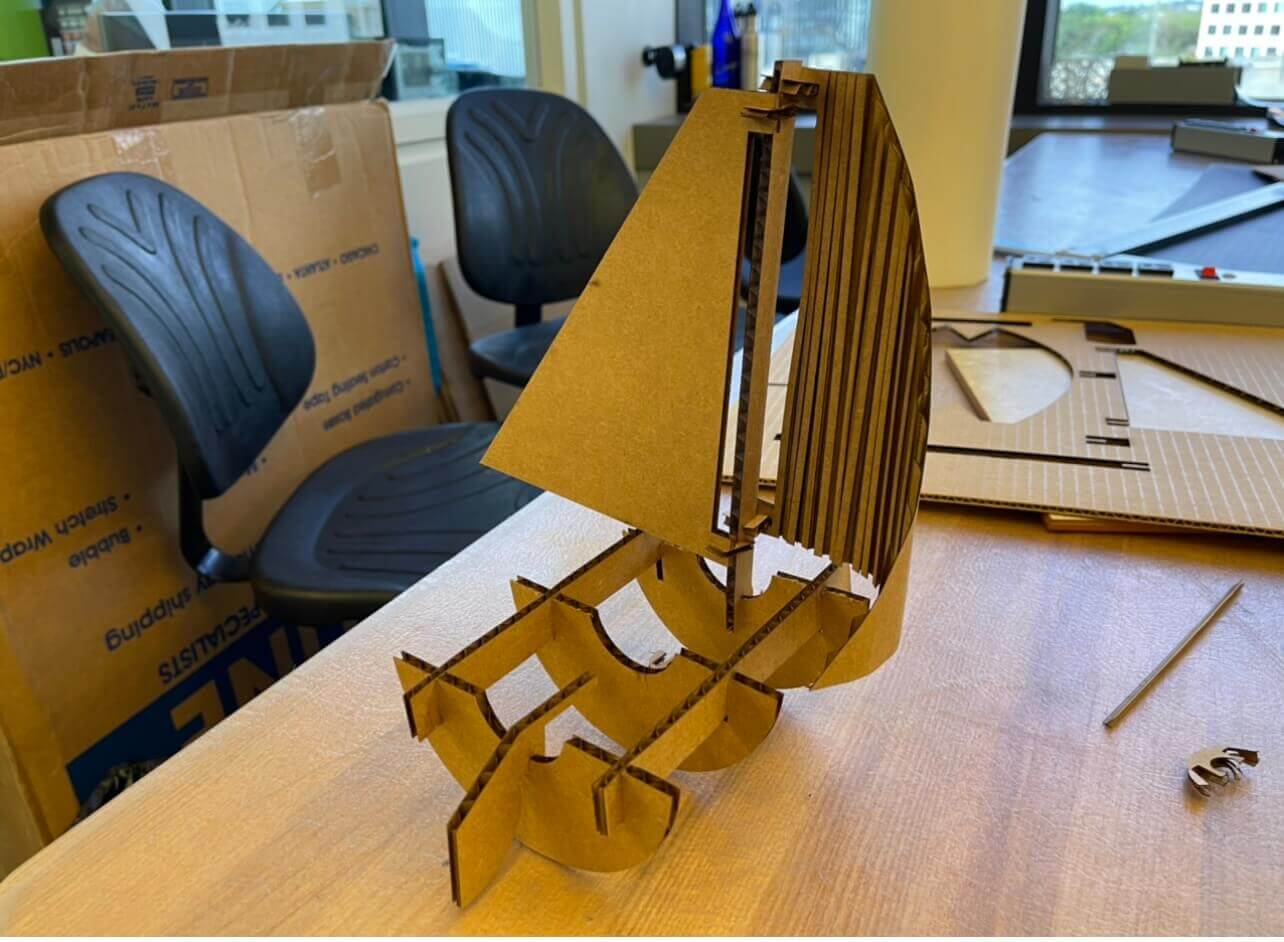
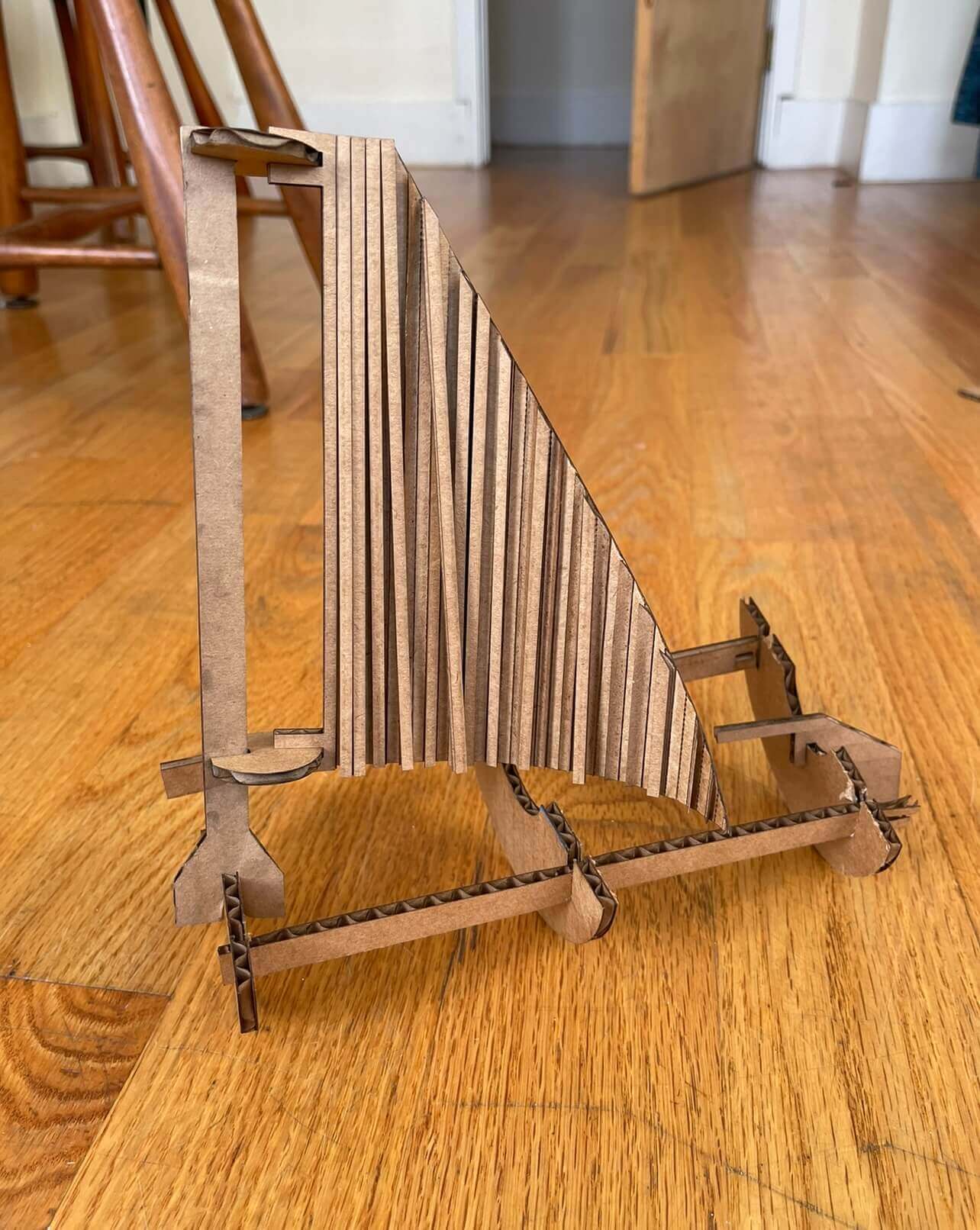
In terms of the parametric component, I tried making certain components interchangeable, such as the mast and side rails, as well as the pins that hold the sails to the mast. Additionally, the hull is designed such that the center component (of the three curved hull components) is mostly there for stability, and can be taken away if needed.
I first tried only flat pieces, but then tried experimenting with adding curves by scoring the pieces. I tried this with the sails, and also tried multiple hull designs but didn't have enough time to properly iterate on them (some of them wouldn't let the sailboat stand upright independently at all). In retrospect, I should've looked more into the flexion designs instead of experimenting with scoring. If given more time, I would definitely have liked to play around with incorporating more flexion into the design, as well as adding more accurate boat components, such as a centerboard, etc.
Click Images to Expand
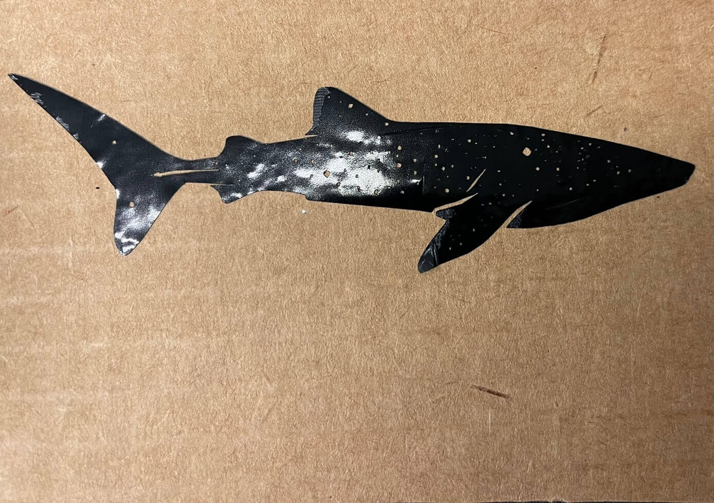
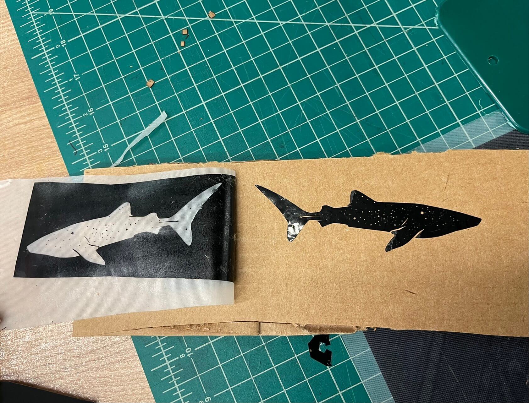
For the vinyl cutter, I chose to cut a simple sticker of a whale shark (I pulled an image from the internet). I've never used a vinyl cutter before, and thought it was a cool process. However, I quickly learned that fine detail was neither the strong suit of the vinyl cutter or my patience. I had some trouble getting out some of the tiny speckles and spots, but otherwise it turned out okay! In retrospect, I would definitely choose something with less detail so it could be seen a little better.
Click Images to Expand
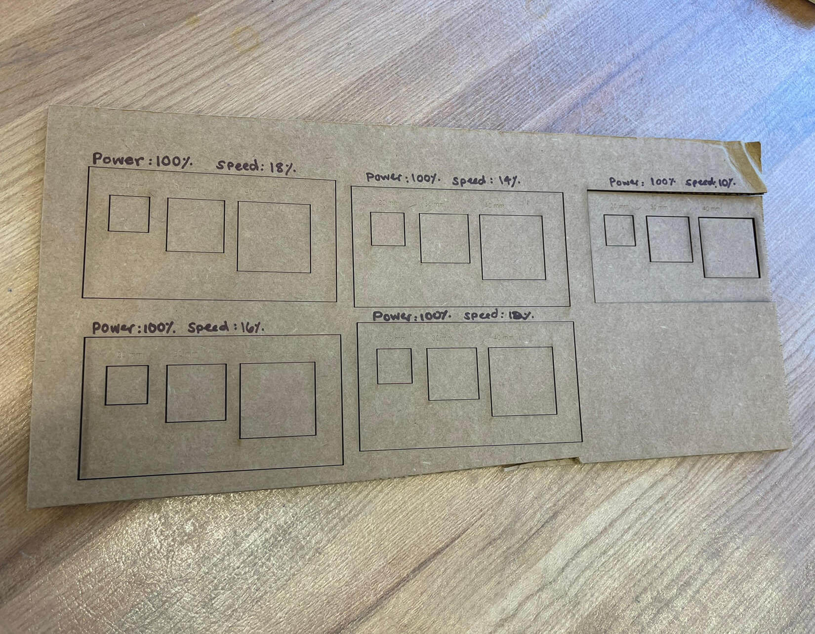
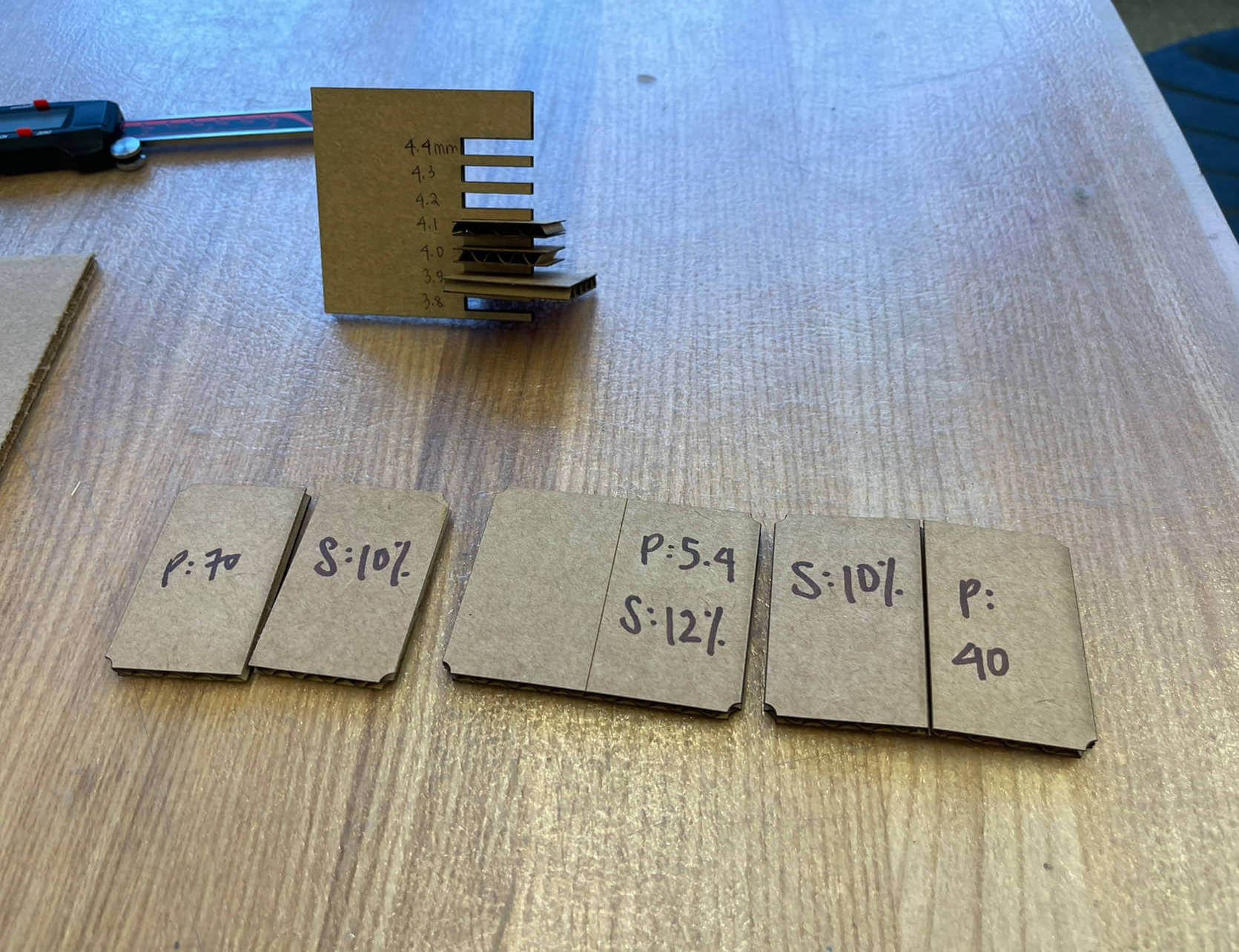
This week's assignment was to characterize your lasercutter's focus, power, speed, rate, kerf, joint clearance and types. As a group, we discovered that the optimal settings for cutting was 100% Power and 10% Speed, and for Scoring, it was 40% Power and 10% Speed. We tested out different square sizes to measure kerf, and on average found the difference between intended square size and measured dimensions to be about .06 mm. For joint clearance, we found an optimal range to be about 3.9-4.1mm.