
Input Devices
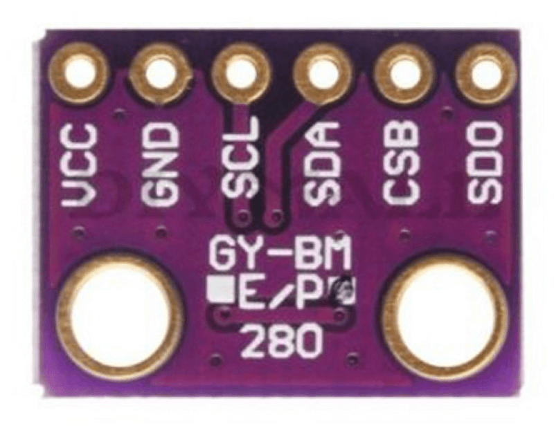
This week, our individual assignment was to measure something by adding a sensor to a microcontroller board that we have designed and reading it. Unfortunately, this past weekend I was fairly busy with Diwali activities, and was behind on my work in general, so the work I'm presenting below is not yet complete. Currently, I'm considering two ideas for my final project: a low-cost coral reef nursery or a shadow lamp that changes patterns based room ambience (temperature, humidity, etc). With either idea, I thought it would be good to try an incorporate a humidity sensor into this week's assignment. Based on stock availability, I chose to use the BMP280, a I2C or SPI Barometric Pressure and Temperature Sensor.
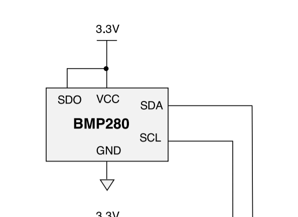
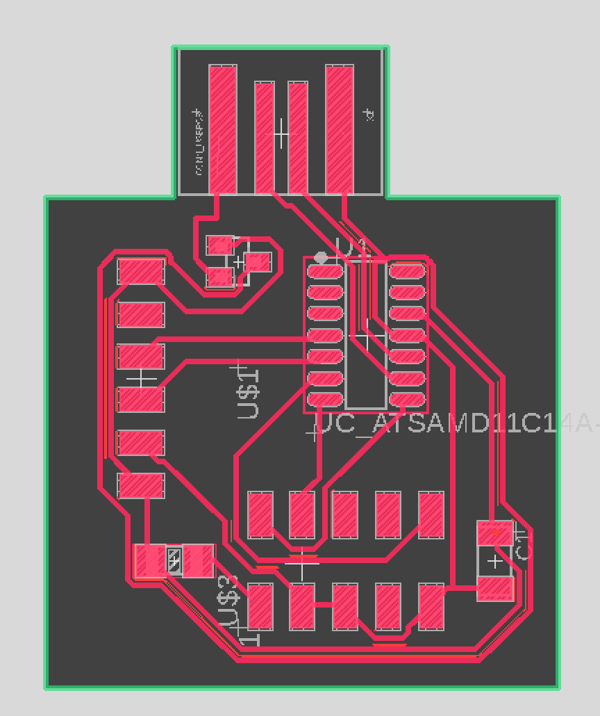
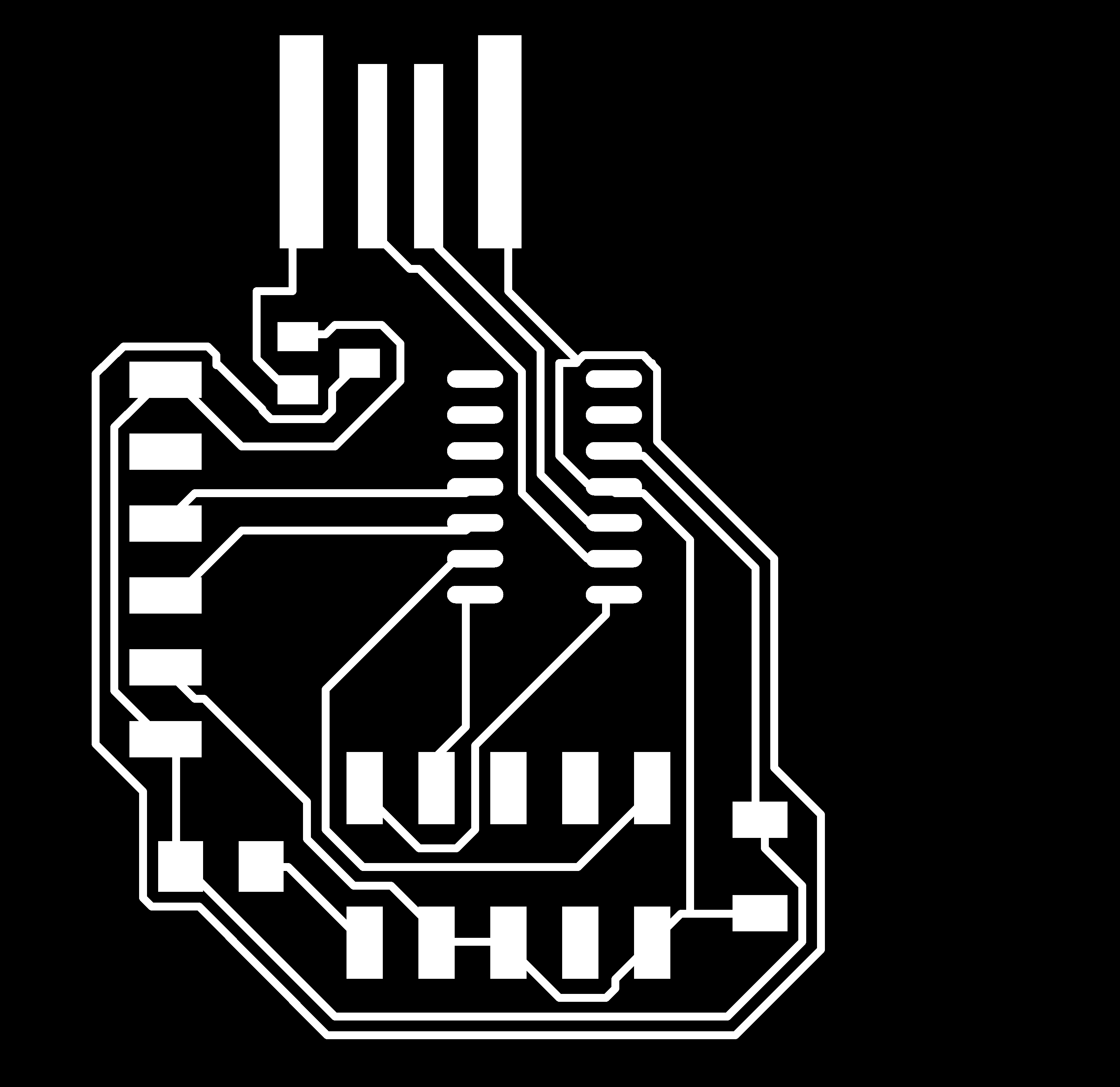
I chose to keep the board fairly simple. It mostly consists of the SAMD11C, the BMP280 sensor, the regulator, and the bootloader pins. Anthony sent me some sources to help figure out how to connect the sensor and the SAMD11C.
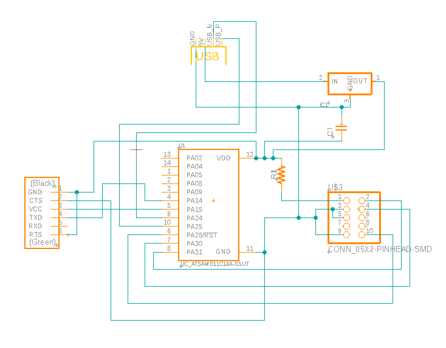
I designed the board using Eagle within Fusion and used the fab design rules. I kept 16mil distance between each trace, and had each trace be 10mil wide. I was conveniently able to use an existing 6x1 FTDI SMD Header part for the sensor. I also unfortunately added a resistor in there when I didn't need to. Here is the final design!


Now that I was ready to mill, I ran into a whole plethora of problems with the Roland, my Mac, and my own oversight. These problems included:
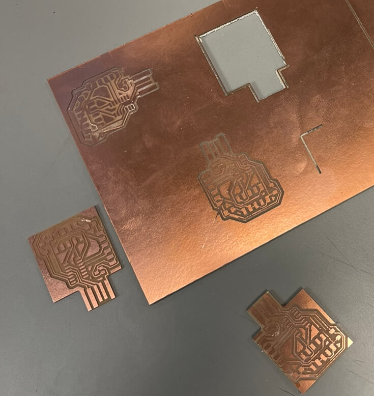
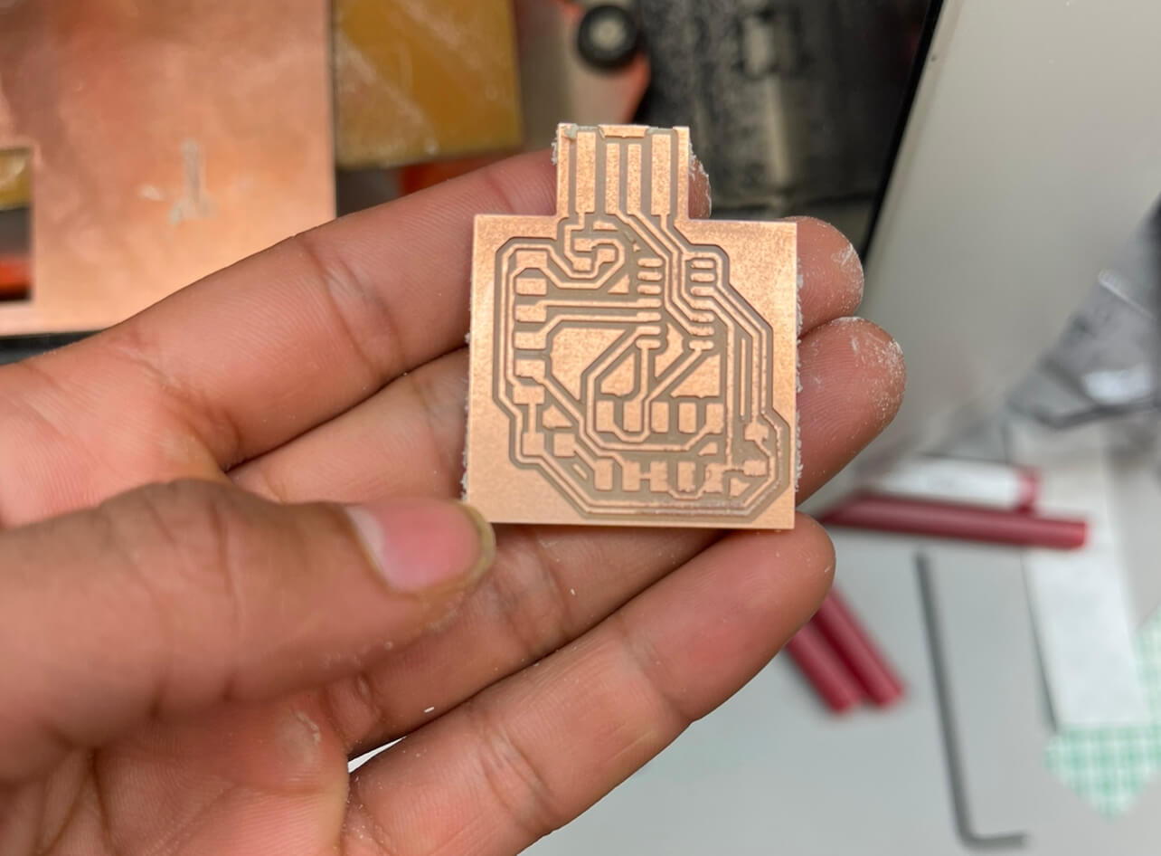
Overall, this took me way longer than expected. After the board was finally milled, I was able to solder all the components and get the bootloader burned after some mild debugging (there was some issue with it calling SPI even though I was using I2C. This was fixed by selecting a NO_SPI option when burning the bootloader)

I then tried to run this code:
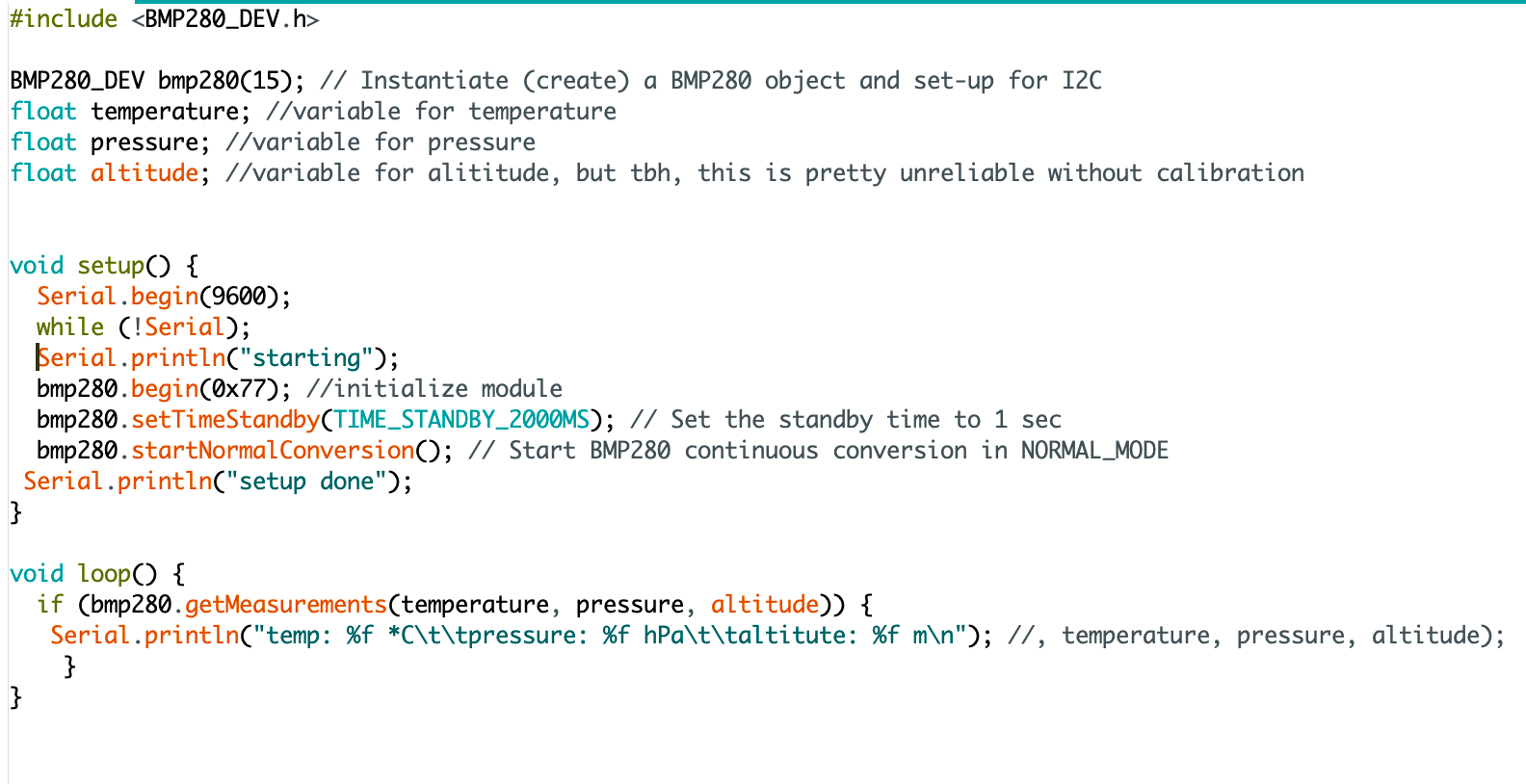
Unfortunately, this would not compile on the SAMD11C, and it was also quite late. I gave up for the night and will continue trying to fix this later.
Update! I later learned my issues were because the SAMD11C had very little flash memory. Next time, I will use the SAMD21C to avoid this issue.
For a bonus, check out this project where I successfully apply the skills I learned in input devices week! I develop this project further in the Networking and Interfaces weeks.