
Output Devices
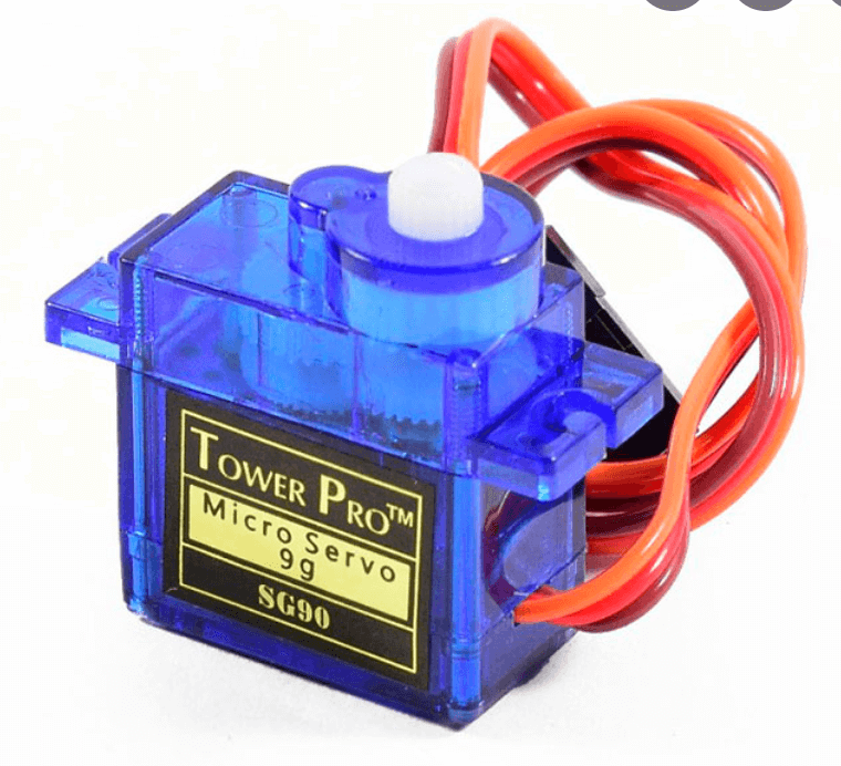
This week, our individual assignment was to measure something by adding an output device to a microcontroller board you've designed, and programming it to do something. Currently, the final project idea I'm considering is building a shadow lamp that changes patterns based room ambience (temperature, humidity, etc). To change patterns, I think I'll have the shadow lamps change panels using servo motors that can rotate them down (out of the light's path) or up into the path's light. Therefore, for this week, I chose to make a simple board containing a servo motor. Servo motors are ideal for my project because you can specify easily position or angle.
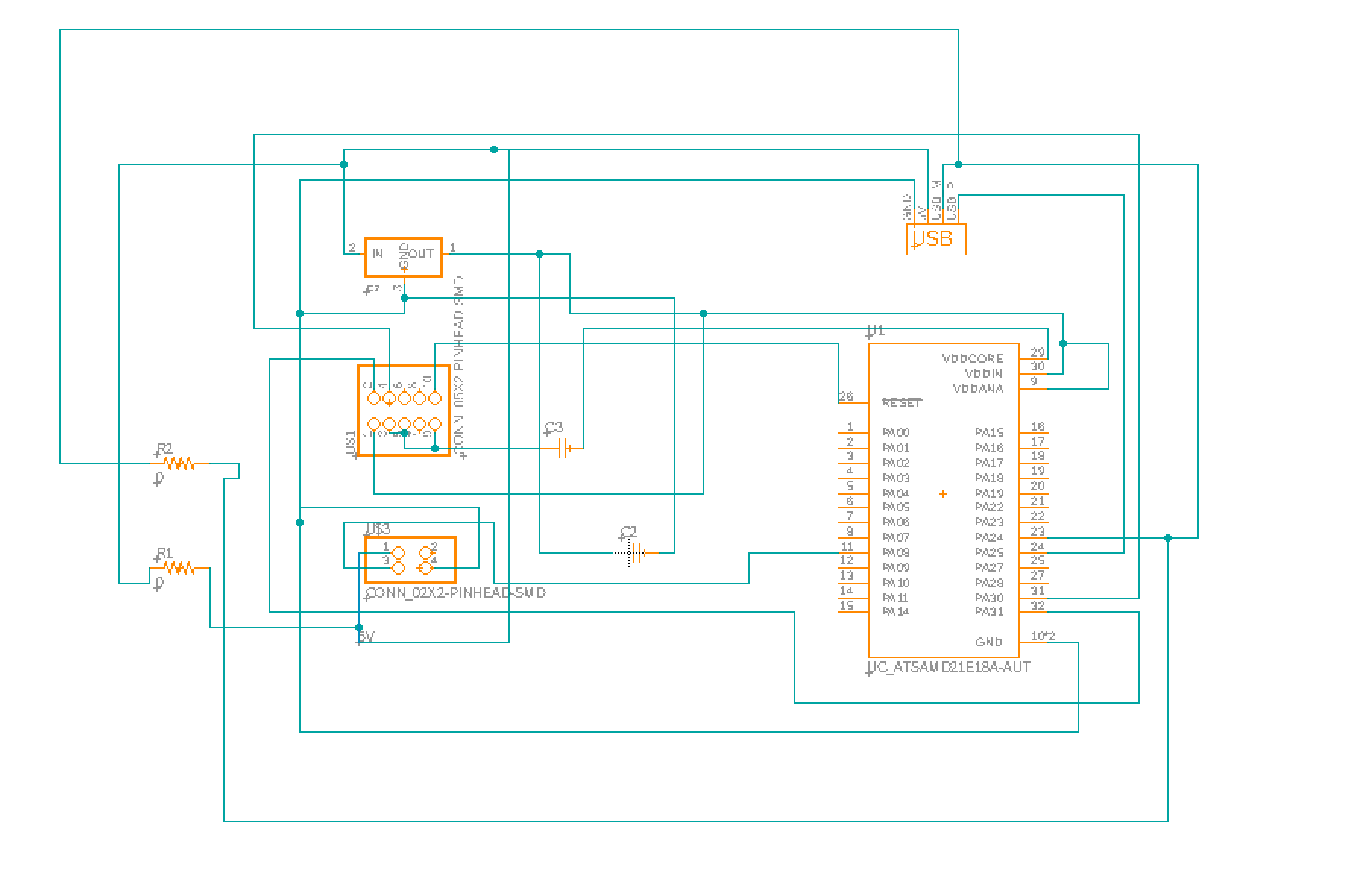
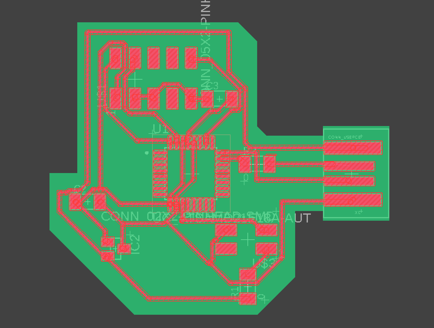
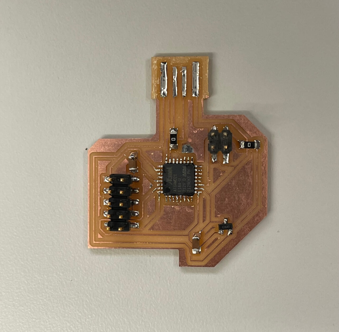
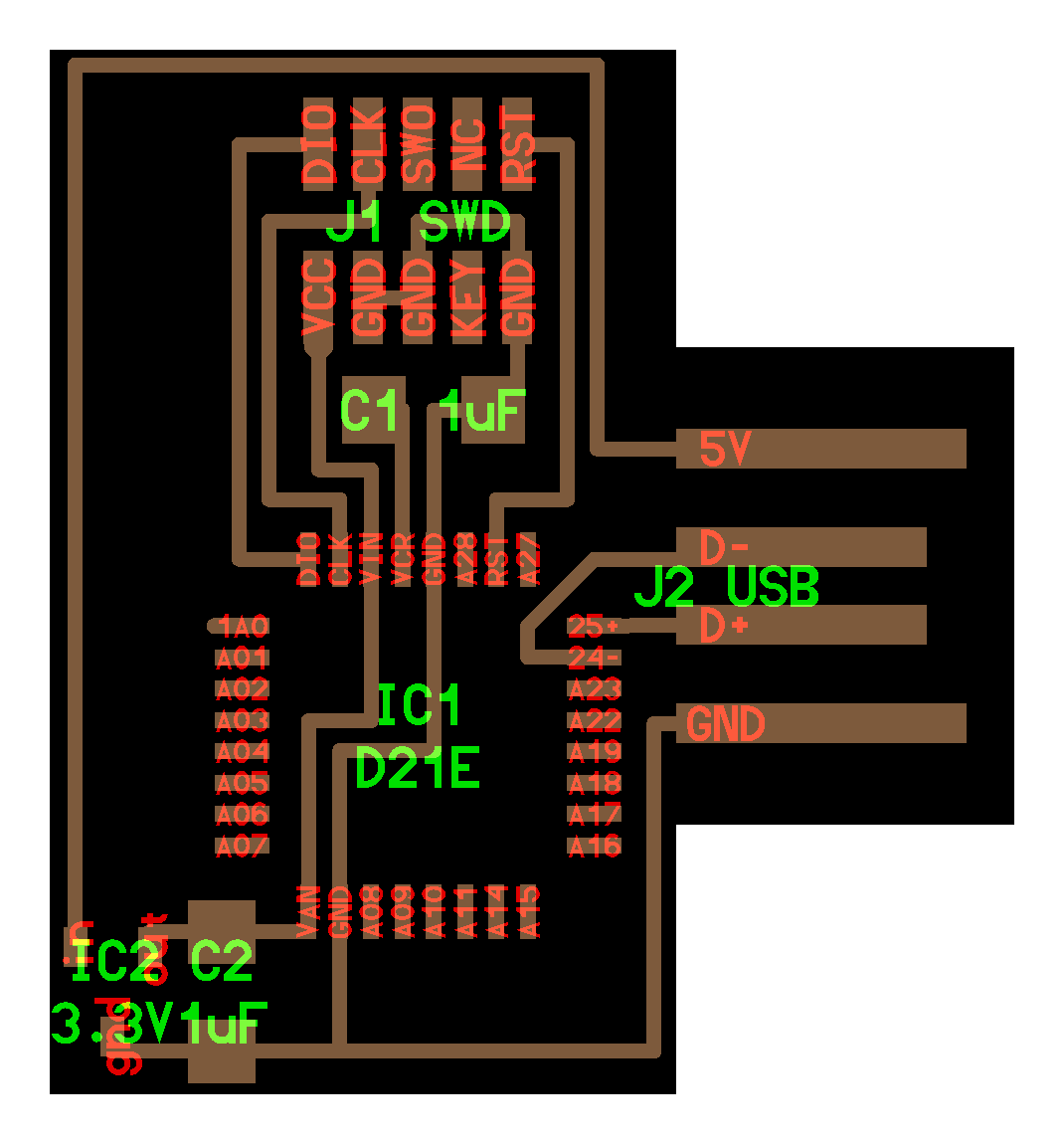
I chose to keep the board fairly simple. It mostly consists of the SAMD21E18A (due to problems I ran into with the SAMD11C memory capacity), the servo motor, the regulator, and the bootloader pins. I used this board along with the datasheet for reference in connecting the SAMD21E to the regulator/USB port etc. I then chose a conveniently located pin for the input to the servo motor. I designed the board using Eagle within Fusion and used the fab design rules. I kept 16mil distance between each trace, and had each trace be 10mil wide. I used a few 0 ohm resistors as jumpers.
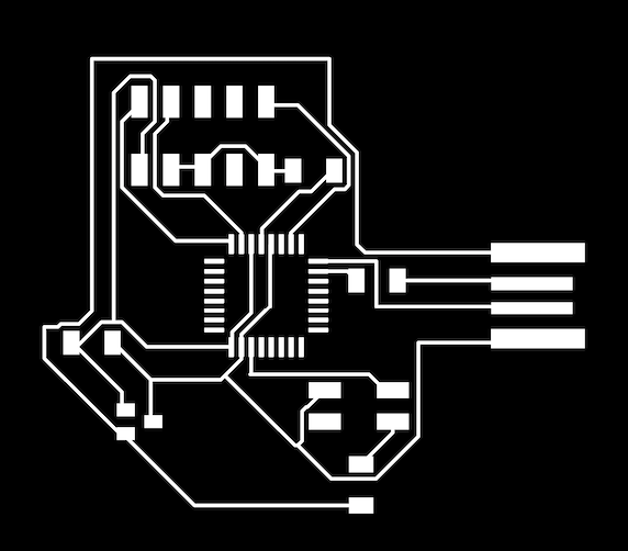
I milled my board using the Roland SRM20. Thankfully, milling went mostly smooth. The first time I tried milling, some of the traces blobbed together, but some were fairly clean (even for the tiny pads on the SAMD21E).
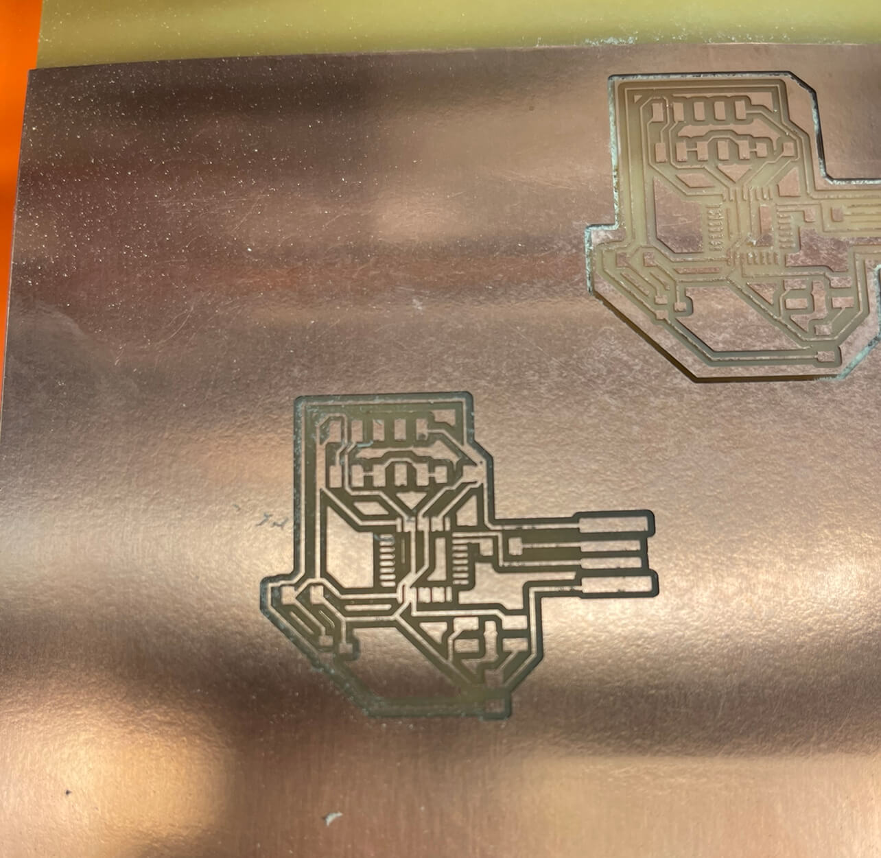
To trick mods, I changed the tool size in mods from .0156in to .0125in, and once I evaluated my tool path and everything looked good, I milled again and it came out fairly well. I then soldered on the components and burned the bootloader!
To test the board, I used example code from the website:
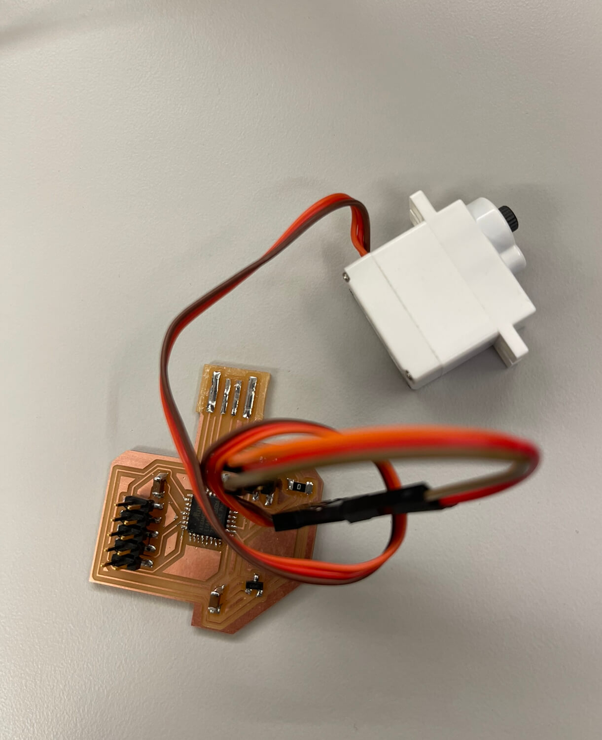
Thankfully, the code worked! The next steps will be to start designing the panel + servo motor interface for my final project.