
Electronics Design
This week, our individual assignment was to redraw an echo hello-world board, add (at least) a button and LED (with current-limiting resistor), check the design rules, make it, and test that it can communicate. I had actually done something similar two weeks ago when I created an octopus. Since I hand drew most of the traces during that assignment, I decided to stick primarily to Eagle for this week. I used Eagle (within Fusion) to create the schematic for my board and the PCB layout.
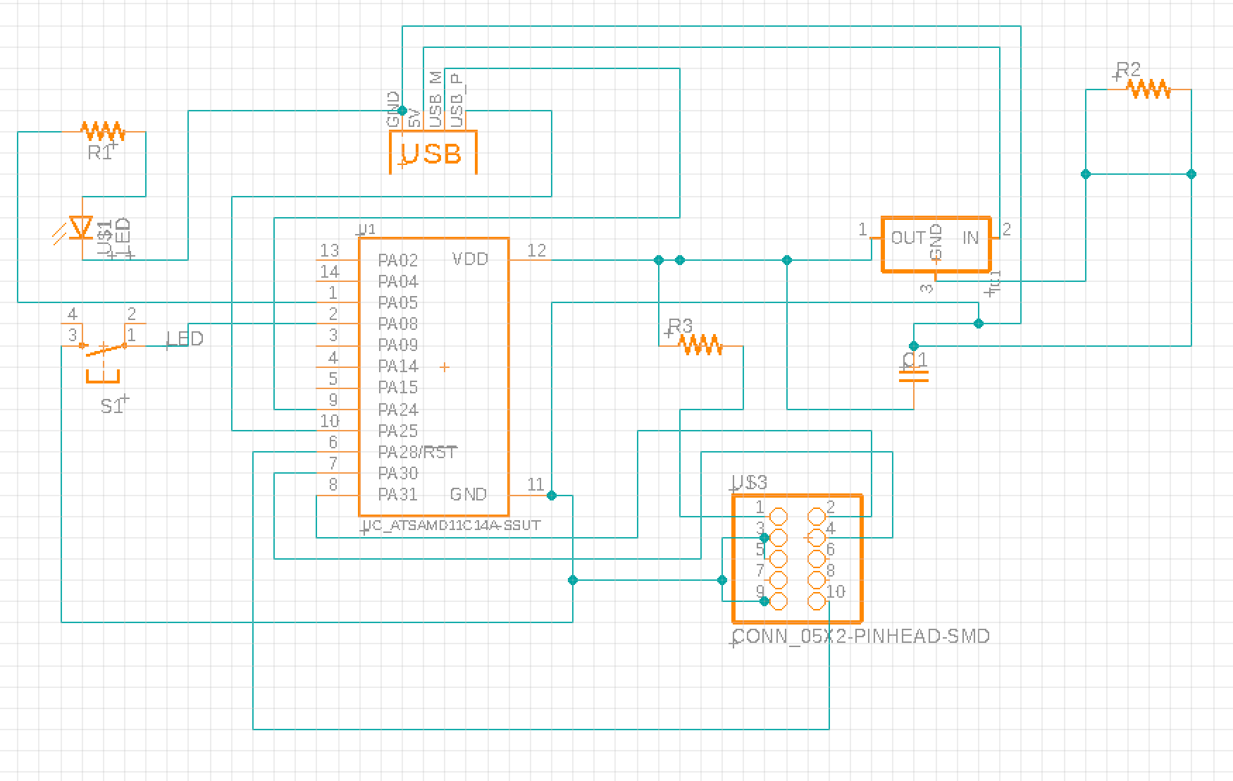

Remembering the design rules we learned from Week 1, I made all of my traces 10 mil, and doubled checked clearances using the DRC functionality in Eagle. I initially really struggled with placing traces in a non-overlapping way, and finally needed to add two 0 ohm resistors to jump some traces. This took me way longer than I expected it to. I wasn't super creative about the circuit itself--I just added a button and a resistor+LED on two separate pins of the SAMD. For the shape, I decided to export the PCB png from Eagle into Procreate in my iPad, and turn it into a genie lamp/diya lamp. Unfortunately, when I tried this, the dimensions got altered, and my first take ran small. I also have a Mac, but in this case doubling the DPI only made it worse. I tried again, and this time I drew on the PCB png itself rather than inserting it into a layer, and while that seemed to work better, the board was still roughly 20% smaller than it should be. Not really sure why this was happening--this process worked fine when I was creating the octopus. For these two attempts, I was using the Roland (which was also giving me a hard time by randomly needing to be restarted every few minutes or thinking the door was open when it wasn't).


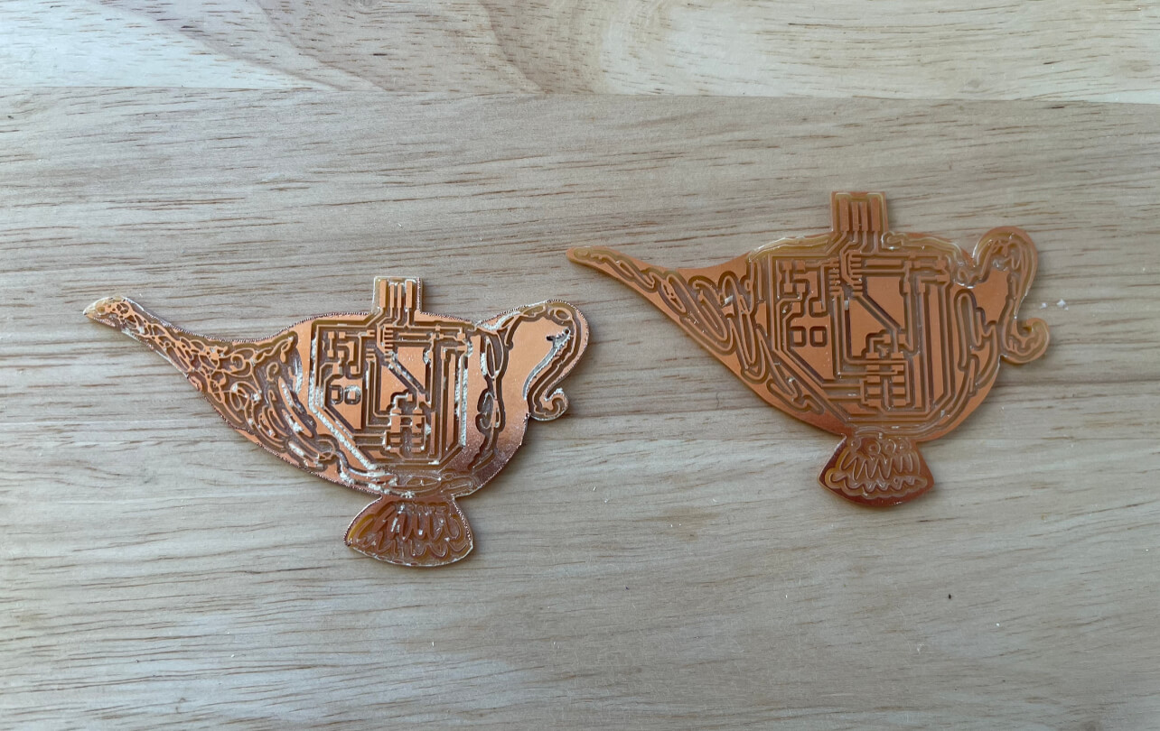
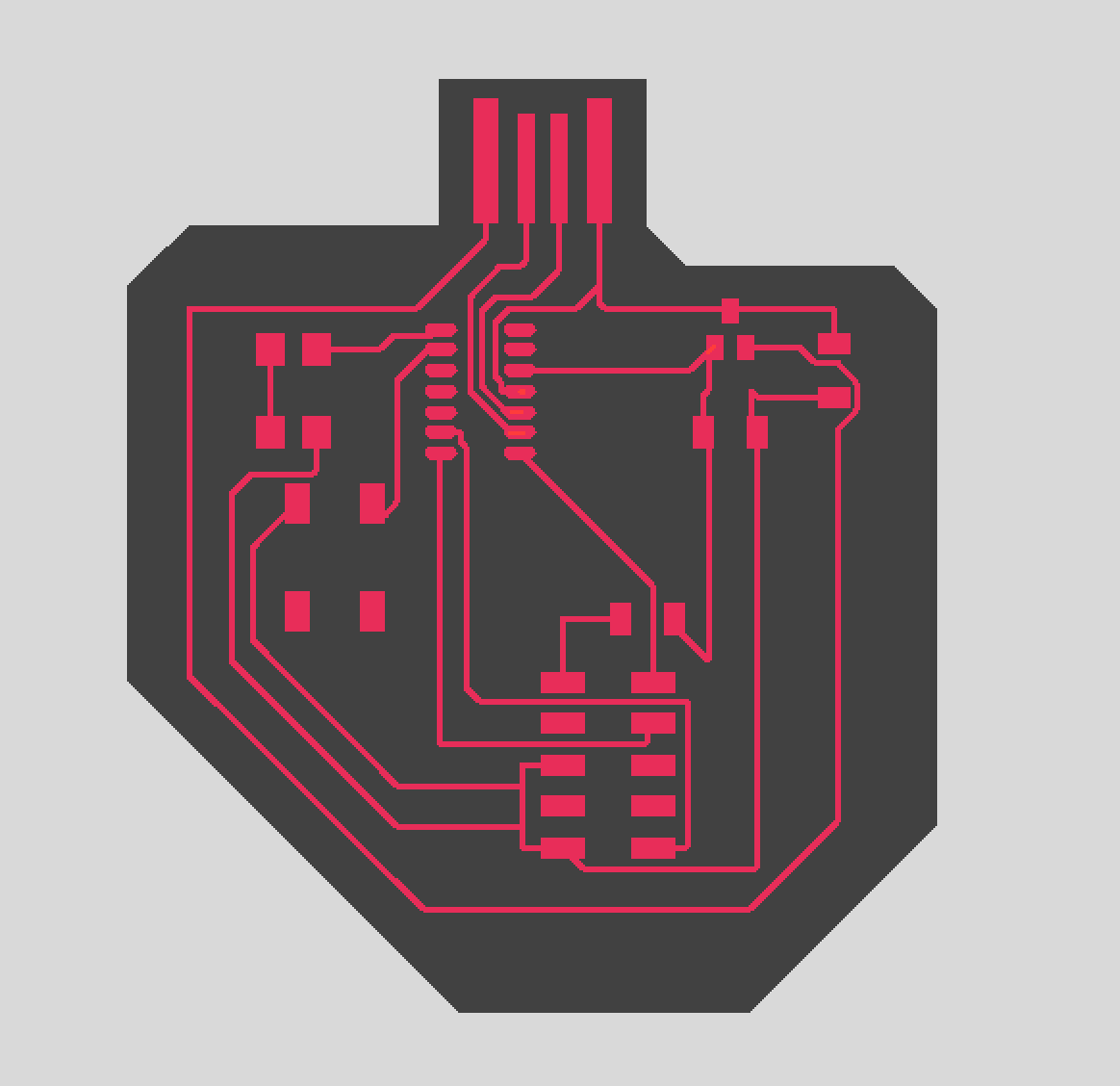
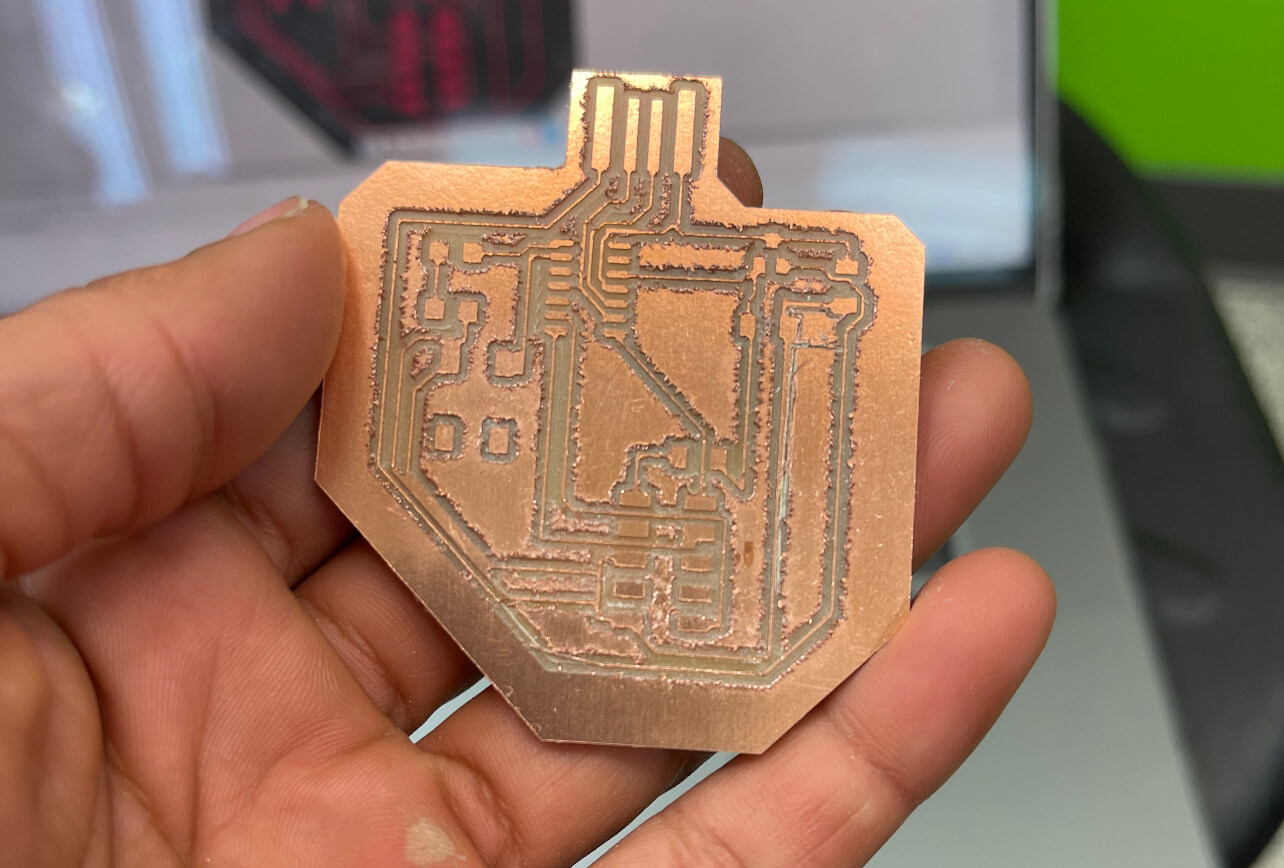
At this point I was annoyed and running out of time, so I decided to quickly make a more simple, somewhat anatomically human heart shaped design using Eagle itself, and tried exporting that. By now, the Roland was in use so I tried using the Other Mill and exporting my files as a .brd. Unfortunately, it would only register either the outline or the traces, and I couldn't make it do both. I gave up and tried exporting the PNGS into gerber, and after that finally (!!) milled, I was also disappointed because it looked messy + a trace had come off, despite my efforts to keep cognizant of the DRC rules.
I'm currently out of time, but I have changed the traces to 12 mil and will remill the PCB after class today, and hopefully finish the assignment soon!
Update! Check out Week 7, where I finished soldering this board and testing that it can communicate!