Machine Building
Brainstorming and Ideation
This week we were tasked to design a machine. The parameters of the project are that we make a machine in a group which performs a complex task, and ideally incorporate all our skills which we have learnt throughout the year.
We started quite early, which attributed to our success. We decided on the project being a group project where all the architecture section students take on a role with regards to whatever machine we will be building.
Sergio proposed that we build a machine which can stack objects, or more ambitiously, build structures. As a group we decided that this was an excellent idea and moved forward to understand what we needed to do. He had a template from a previous project which he had worked on but not manufactured from scratch like we were going to do.
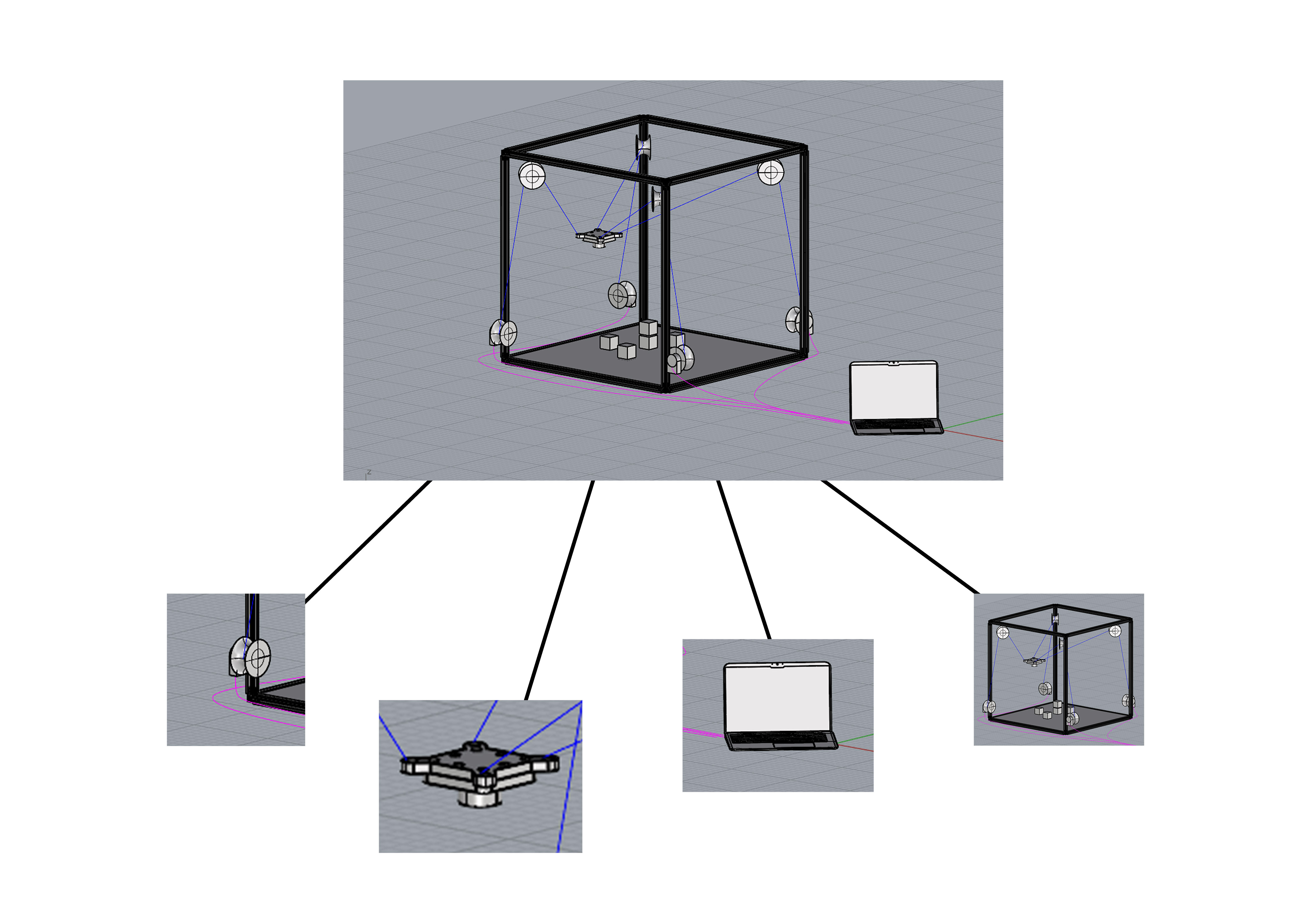
We started by discussing the different components of the project whilst weighing the amount of work each section would be assigned. Accordingly, we tried to mass the relevant amount of people and skills to each task. Initially the process was quite chaotic but once we started with the project, we were able to gauge each of the timeframes and the skillset discrepancies of each member to better assign them.

Because we started discussing the project before we completed the previous week (How to make Something Big), we could spread our workload over a greater period of time. I suggested that we try and complete the electronic component of the design before the weekend (it was Monday then) because if we might need the expertise of someone like Anthony or Quentin so that we can troubleshoot the following week. Everyone concurred.
Machine Description
The size of the machine was situated at 32inches to be able to fit through a standard US doorframe as we needed to think about the transportation of the machine.
We wanted the machine to be able to function on larger scales, such as attaching the pulleys to the corners of the room, and then be able to use a whole room as a frame, therefore we opted for pulleys for 3-dimensional movement, over a cartesian slider system like a conventional claw machine
First consultation
We met with the TAs at the CBA right after our meeting. There we discussed the plausibility of our project, the components which we will require and if the preliminary sections were correctly structured.
Quentin and Jake were excited about the project and suggested some things. 3 pulleys might be better than 4 due to the inherent stability of the triangle over the square. However a triangle will limit our movement to the interior of the triangle and not the whole square system and we ended up deciding on a square 4 pulley machine.
At that stage we wanted the machine to operate as a Tetris stacker but stacking irregular objects in 3d space would be quite a challenge. Alicia suggested that we make the blocks with magnets so as to be able to generate the shapes beforehand and stack them with a magnet system. Jake suggested that we take this one step further and instead of using blocks, we could use balls because they naturally slot into one another to form stable structures if its base is stable.
This first consultation revealed that the pully system is going to be the most challenging part of the build.
Block and Grabber
I was inclined to the Block and Grabber section of the machine. I think it would be a nice mixture of things which I could already do (Object Manufacturing) with an electronic component (The electromagnet).

Grabber Bracket Design and Manufacturing
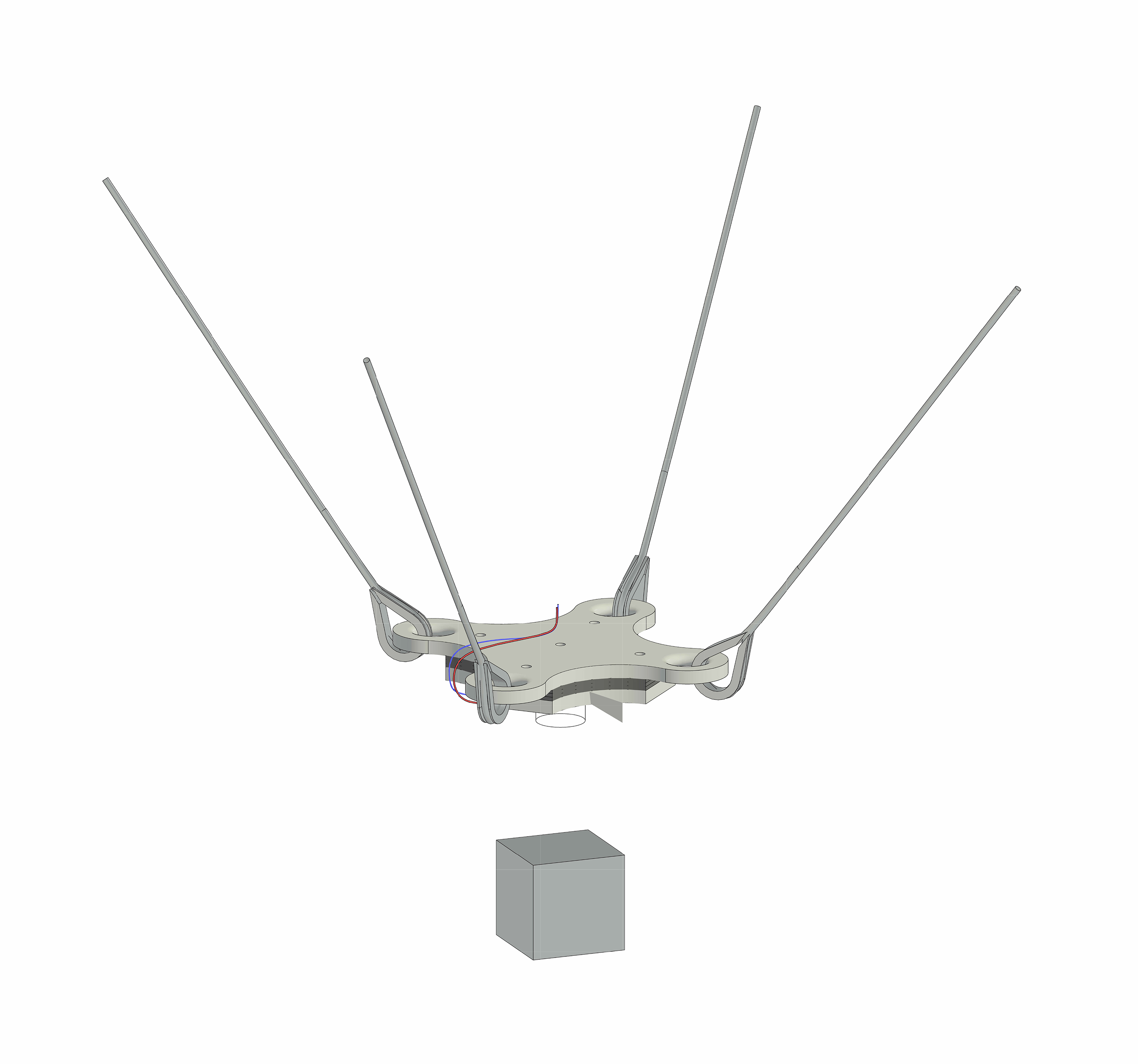
All of us (Me; Reishan; Ahzin; and Nour) met to discuss the assignment of tasks. I opted to do the bracket which joins the pulley cables to the electromagnet. There we more details than anticipated.
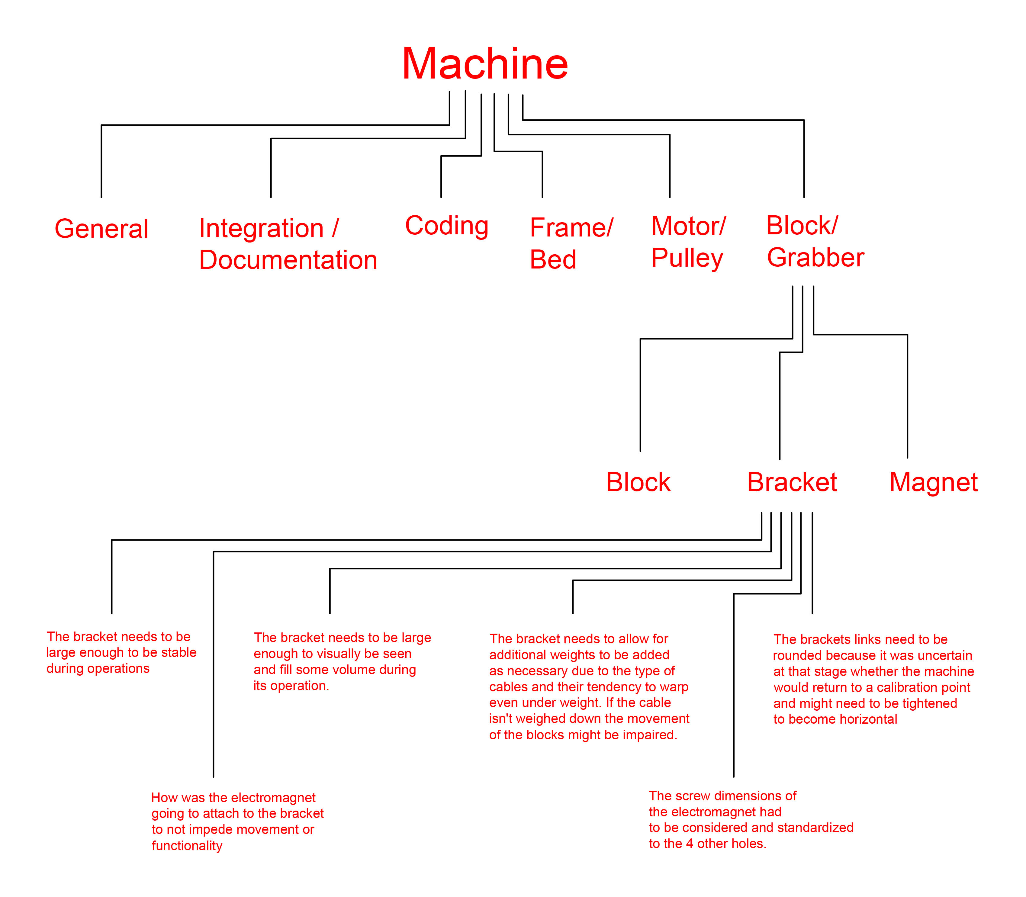
The manufacturing of the bracket was quite a simple 3D print, however the small steel weights had to be laser cut to match the area of the bracket and some small adjustments had to be made.

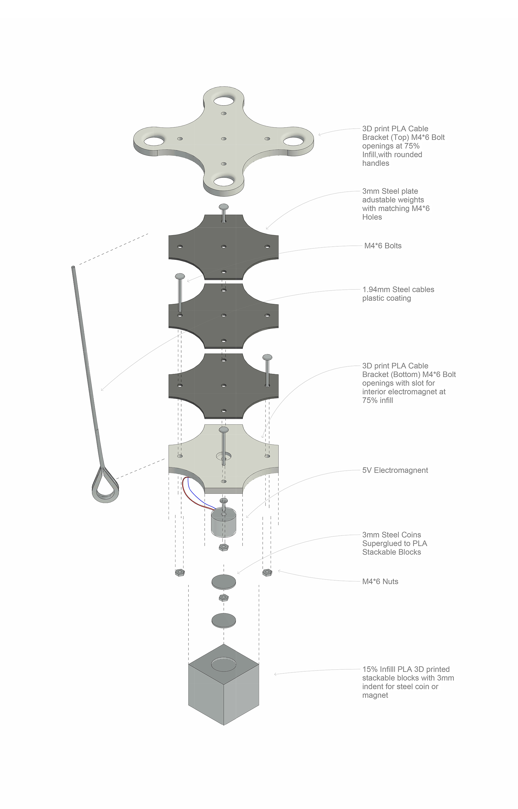
Design
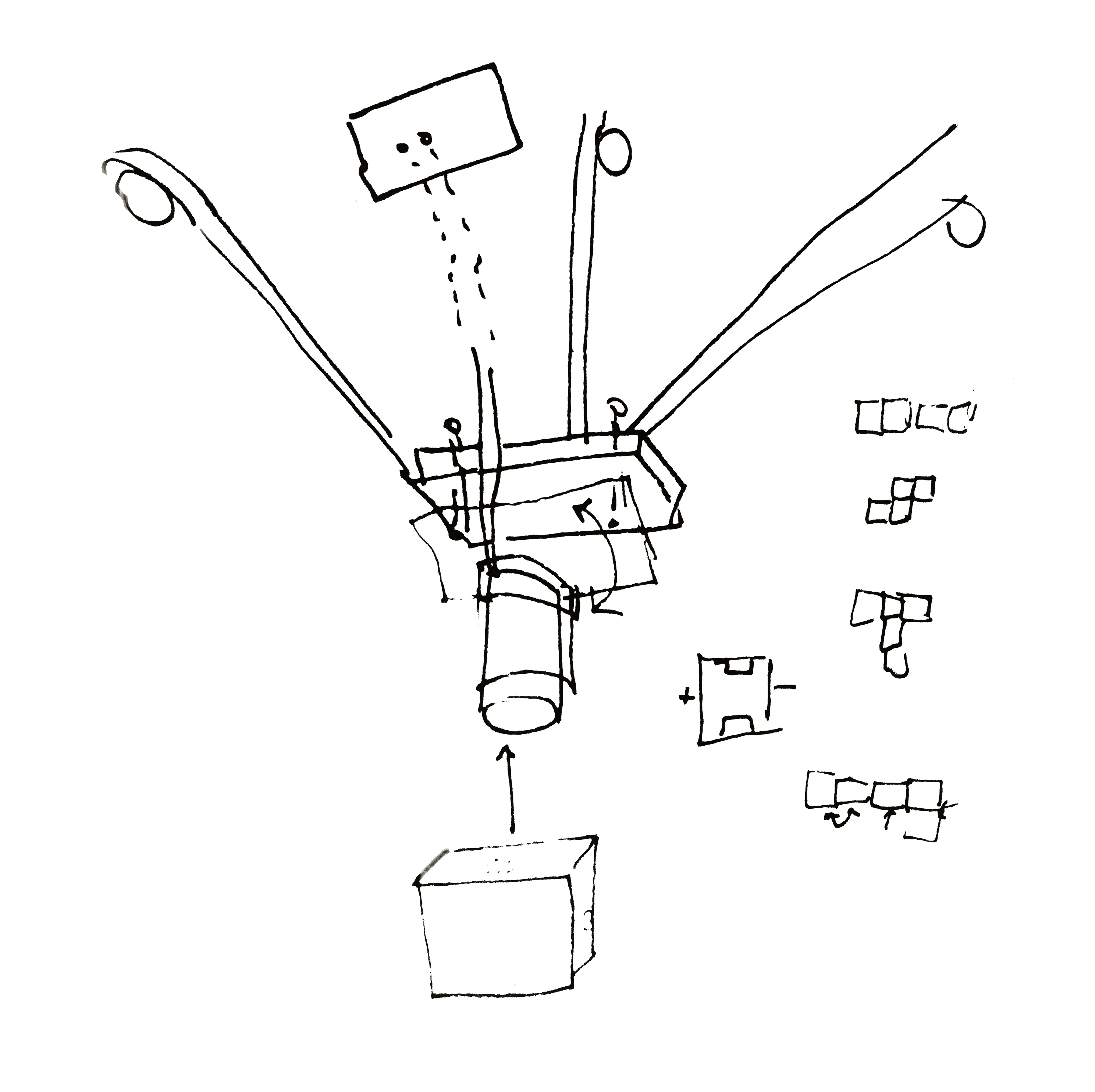
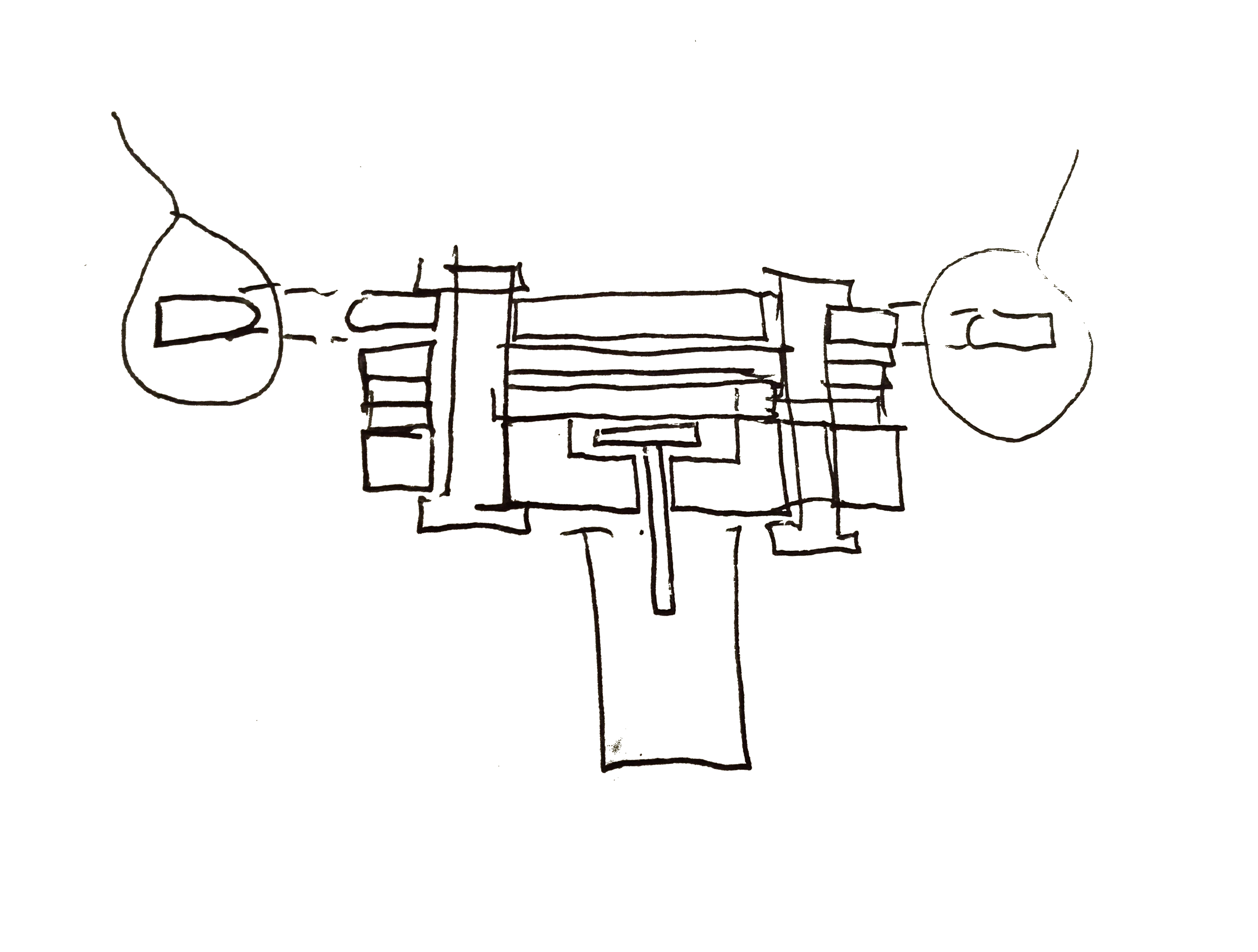
Second consultation
We started by testing some of the electronics and having the group come together before the final assembly of the machine. This was sort of the Midterm, and the next day would be the Final assemblage. The code was up and running and Jake helped us with testing the electromagnet which in turn led us to change the design of the Blocks.
Integration and Third consultation
After the blocks, brackets, components and wiring were tested the whole machine was assembled.
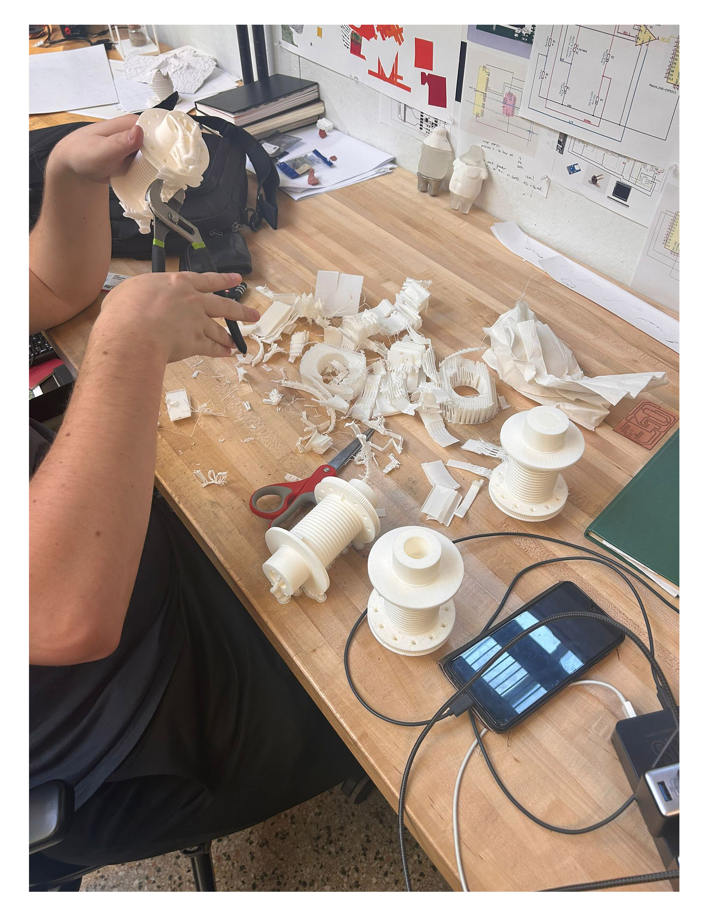
During the course of manufacturing, we hit some snags and luckily printed extra components as some of the other 3D printers were quite unreliable and didn’t finish their prints on time for assembly. It was important to diversify our inputs to minimize risk. Because some of the sub- groups were finished with their segments before other groups, we started helping where we could. I ran some 3D prints and started with the soldering of the electromagnet.
We used the Nasa splicing of wire method to successfully attach cables to one another. Their strength was impressive. Seeing as we stripped two ribbon wires to attach to the existing wires of the electromagnet, we covered each connection with capped on tape so as to isolate them from one another. After we soldered the wires, we tried to cut open some white heat shrink wrap tubes, to try and cover the exposed wires for aesthetic and mechanical reasons. We were unsuccessful in trying to heat gun them or use the soldering iron to close It because we cut open the tubes to place them around the wires post assembly.
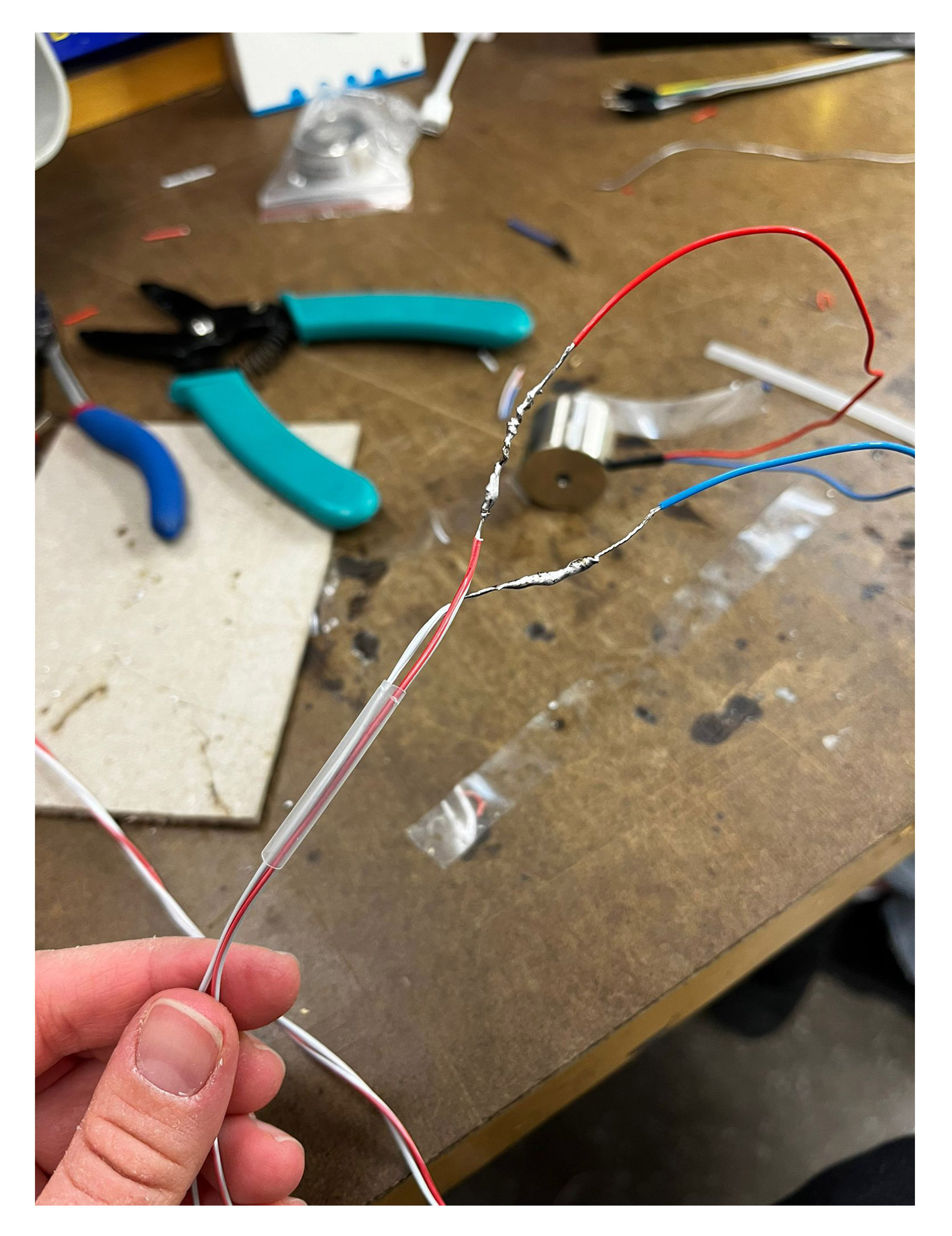
Eventually we settled for using a second layer of white insolation tape.
We came back from EECS to start assembling and testing the final product. Unfortunately, my week ended here, and I could not attend the final machine wee presentation due to family matters. However, at this stage I had done my part and was satisfied with what I had produced.
Other notes
Other notes
What was interesting about this week is that I built in a system to attach weights to the bracket, and did foresee the weight being an issue, but the group ended up attaching weights post assembly due to time constraints when I wasn’t there. I could see on some videos shared during the testing phase, that the bracket wobbled when it would move. Furthermore the cables were attached at a central point above the bracket.
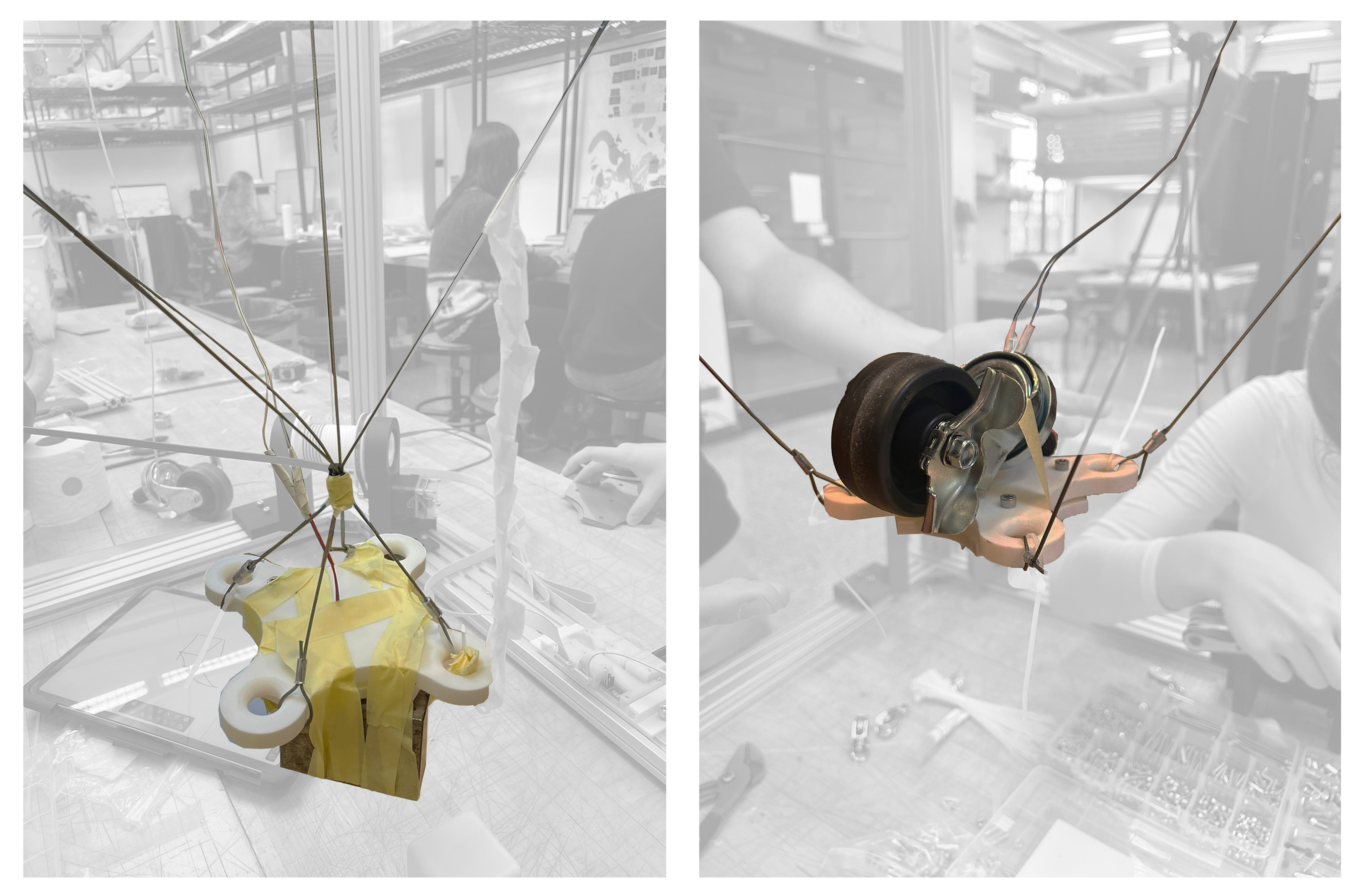
Was this a weight issue or cable issue?
Or maybe I didn’t make the purpose clear enough for the plates which needed to act as weights?
Or maybe it was too complicated to take apart a working machine just for adding additional weights?
Or maybe the surface area of the bracket was too large and made to be too unstable?
These are all questions which I hope to find out after the break?
Workflow

