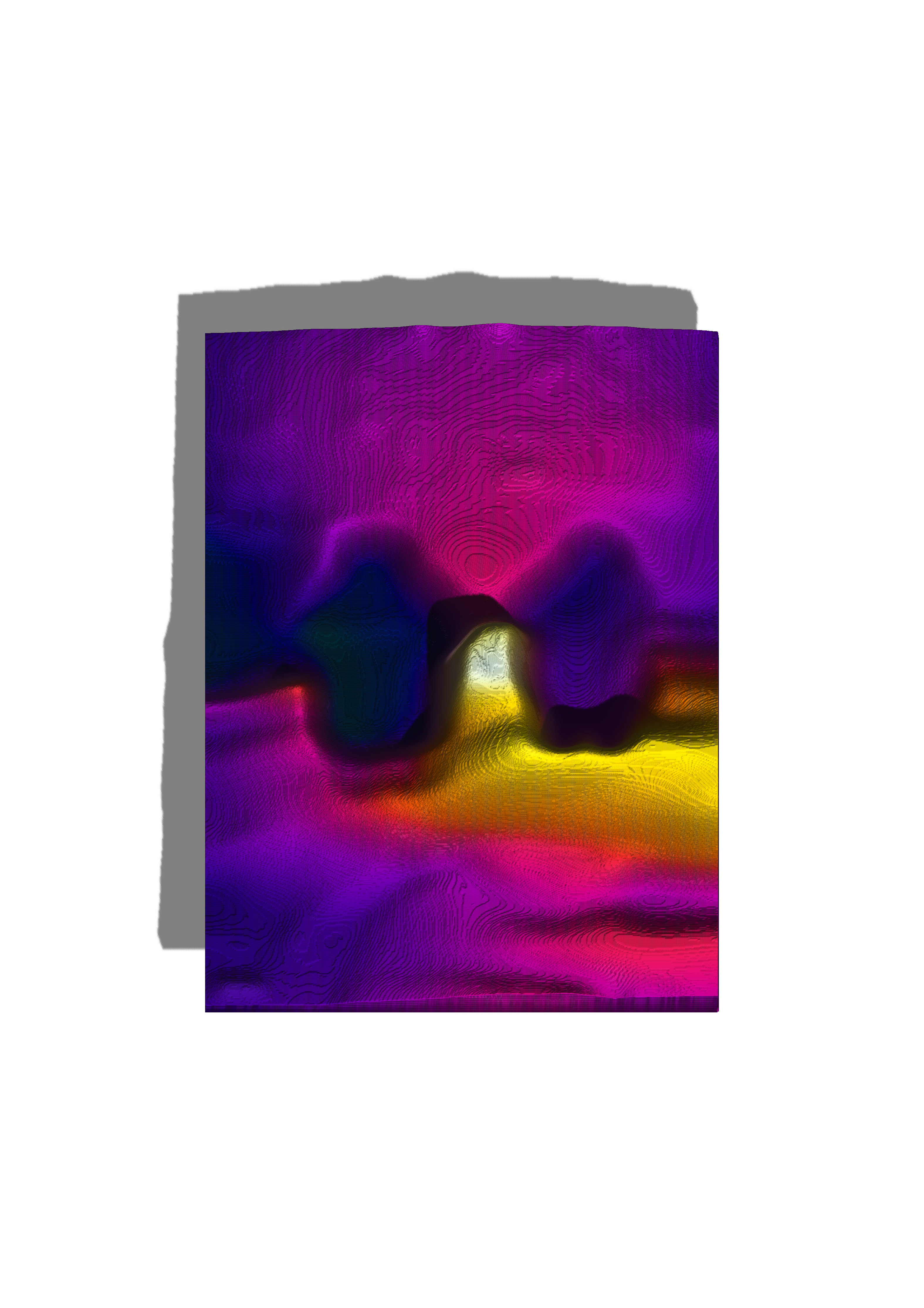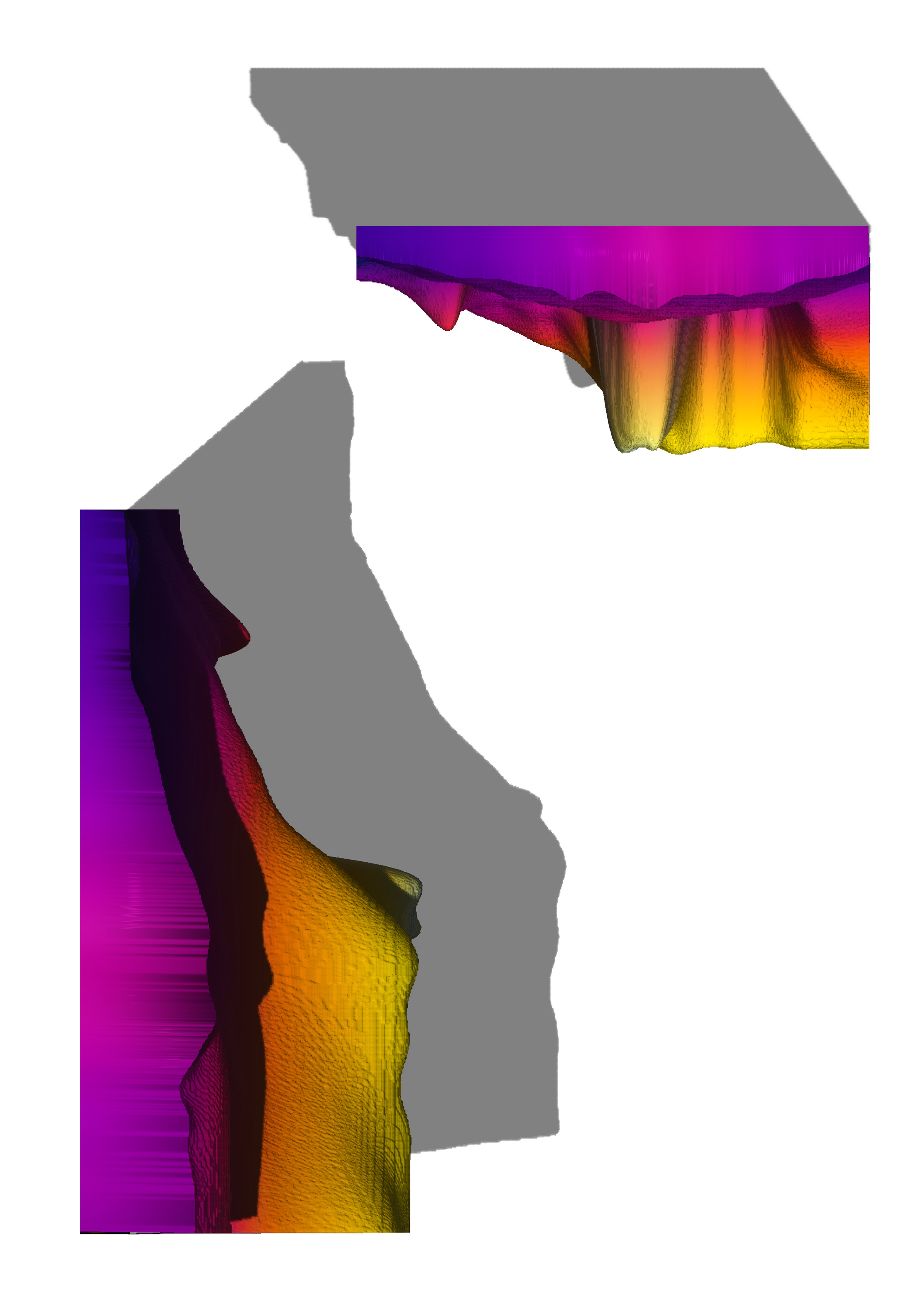
This week I decided to do experiment with two types of 3D printing methods, filament and powder printing. I had previously had things printed on 3d printers, so I am sort of aware of the limitations of the medium, but after interacting with the machines I have gained new appreciation for their limits.
I Started of by modeling my powder printing model, which was going to be the cross section of a scale prototype birdhouse. I started by drawing the profiles of bird’s wings, sweeping them in Revit and combining the shapes in blender.
I am still in the process of mastering blender – a program which everything I use it; I garner more and more respect for the art that is 3d modeling. There is a certain intuition which is needed to understand if your workflow is going to waste or save you time. My workflow usually does the latter. I added these shapes together and tried to re-mesh the joined geometry. Here I wasted 1.5 hours after my computer tries to generate the correct geometry.
After much struggling, I managed to join and decimate the geometry to simplify my workflow. What decimate does is it removes unnecessary information (which is usually stored in the form of geometrical points – or vertexes) and simplifies the shape, whilst still not losing all of the crucial details.
Then I used Boolean to carve the shape I wanted to powder print in the form of a cross sectioned square. I then exported this information to STL. Before that I made sure that the mesh was watertight (meaning I wanted to make sure that the mesh could be 3d printed).
Powder printing
Having worked with filament printing before, I was optimistic about my chances to make a success of it. I wanted to turn some mesh I found online into a kind of movable textile or fabric.
I had a vague idea of how this object functions before I worked with it. Initially the design was meant to be some kind or fidget toy. I then took the mesh apart to isolate a single piece of the system. Imagine taking apart a chain until you are only eft with a single ring.
I tessellated the module and made a 25x25 grid of the objects which was about 250mm squared on the bed of the 3d printer. The estimated time was 1day and 5hours.
I consulted the wisdom of my sensei (Jen and Sha), and they said that due to the nature of my print, It will take quite some time to print because there is little infill and many lines which the printer has to follow before completing a lap of the mesh.
Jen suggested that I test a small part of the mesh so as to see if the overhangs, rafts and the separations will be adequate so that if I decide on committing to a print which will take a day – it will at least do so successfully. I tested the geometry and 4 of the chains took 20 minutes to print.
Whilst it was doing so, I experimented on other variations where I decrease the amount of chains, decreased the height of each chain section and took the top and bottom off of each chain. I came to the realization that decreasing the amount and height was the best ways in which the speed of the print could be increased.
Workflow

Filament printing.
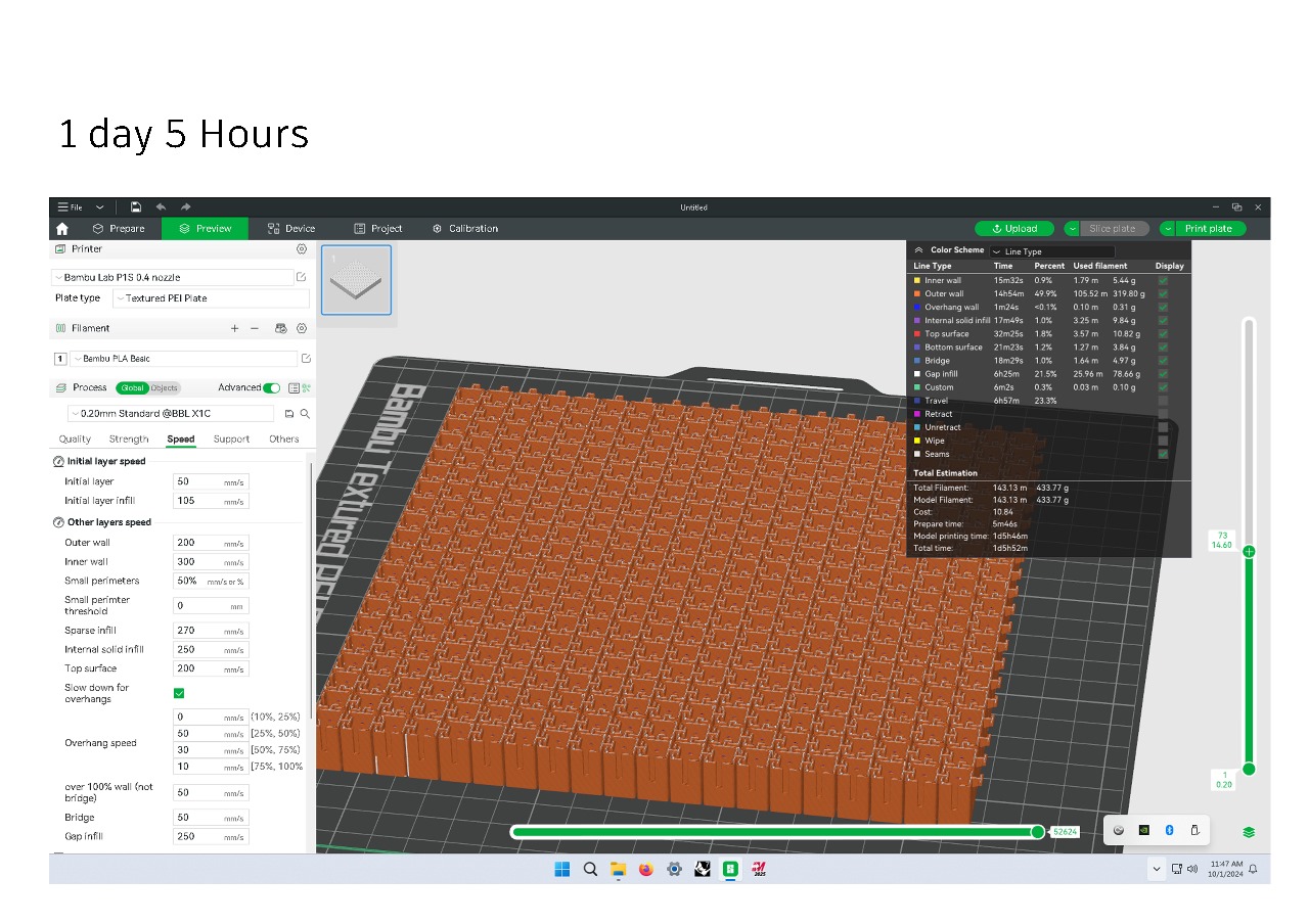
I was quite shocked when I discovered the initial amount of time it would take to 3d print the first iteration of the model. Then I remembered that there were several things which I could do to change the time of printing.
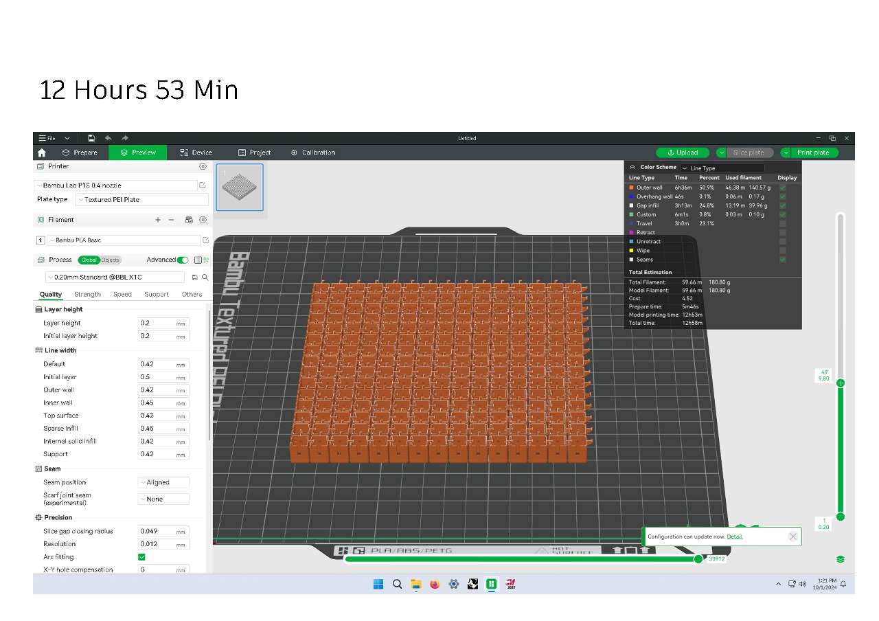
The obvious thing was to change the amount of material on the board by reducing the amount of chain links in the system. I however didn’t want to make the grid so small that the idea wouldn’t be carried over to the viewer. I had to keep looking.
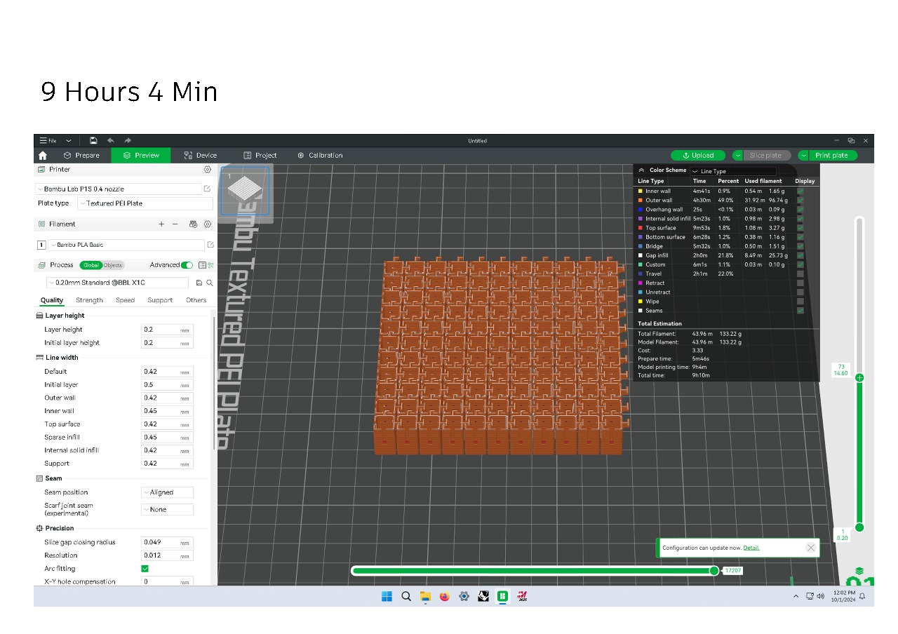
I Removed the top and the bottom of the links to see whether the lateral printing would have a substantial effect on the time it would take to print. It was better but still needed simplification.
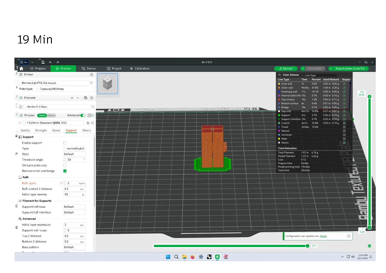
I printed a quick test print of the original links, to see if it would even still be possible to print at all. My test print confirmed that my suspicions that it would work so long as I do not neglect the crucial components like the thickness of the walls and its closeness to the sides of the other chain links.
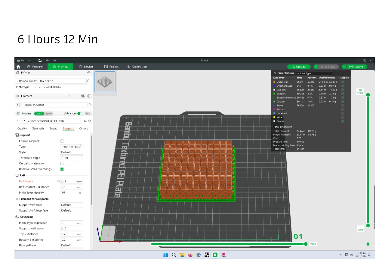
This image shows the final design which I settled on in the end. The final product speaks for itself.
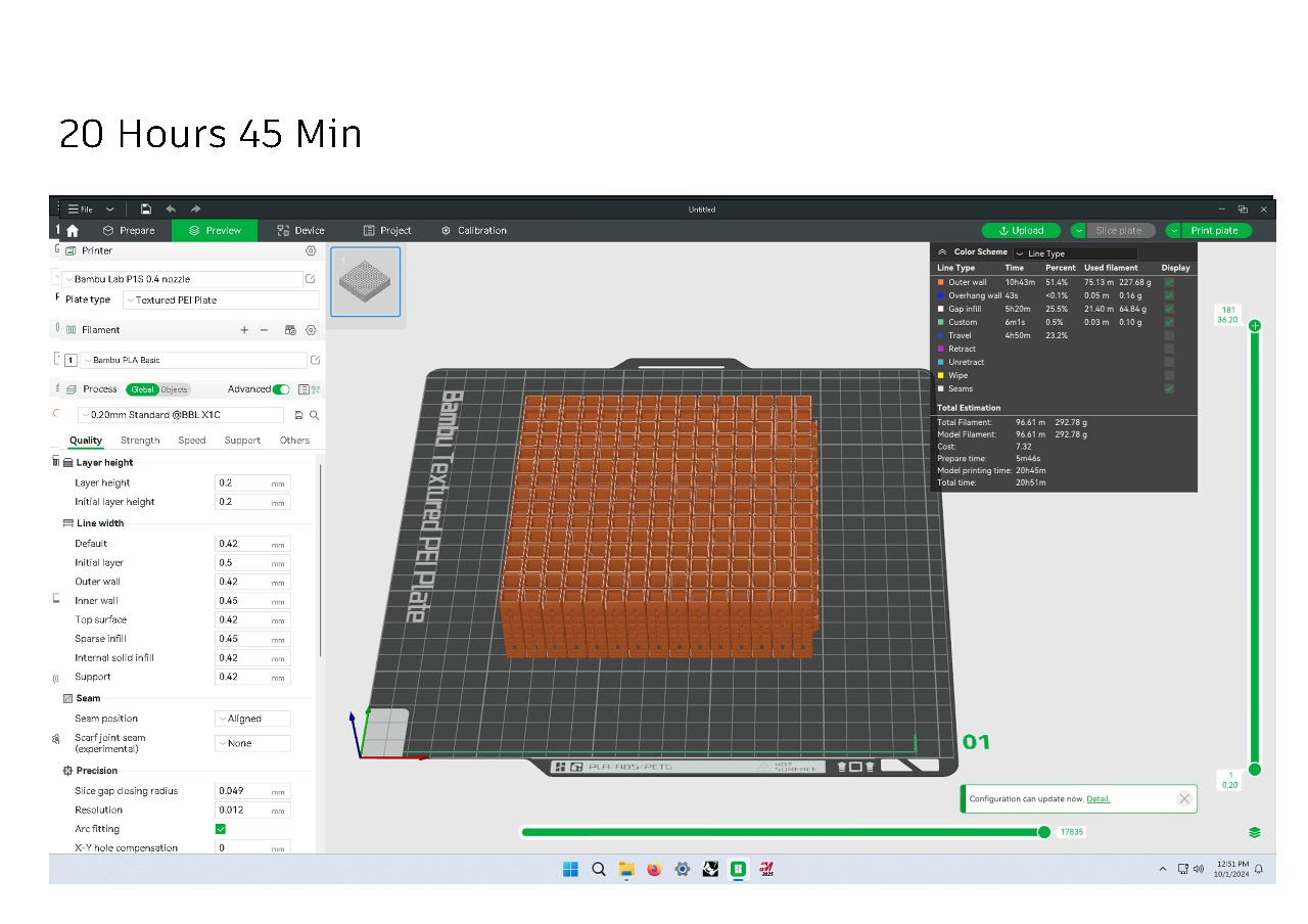
One of the earlier iterations where the individual height of the units was substantially higher, and the design also incorporated more components in a 15 square grid.
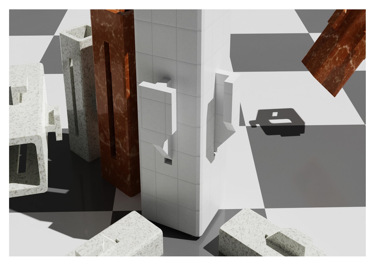
The geometry of the final model uses 45-degree angles to support the hooks on the inside of the system. This is a crucial detail seeing as the design does not leave any room for internal supports.
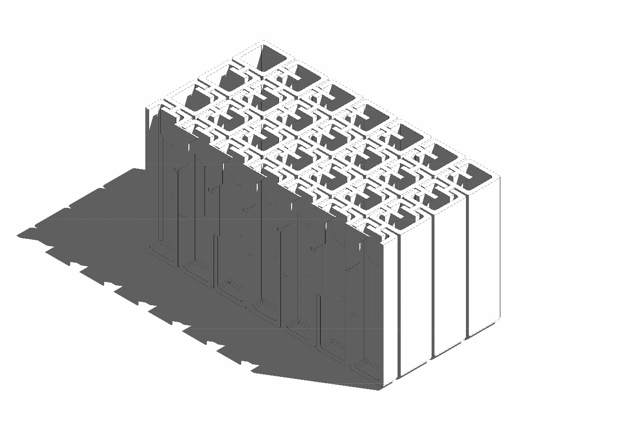
A cross section through both profiles of the system shows how the hooks and the slots interact with one another.
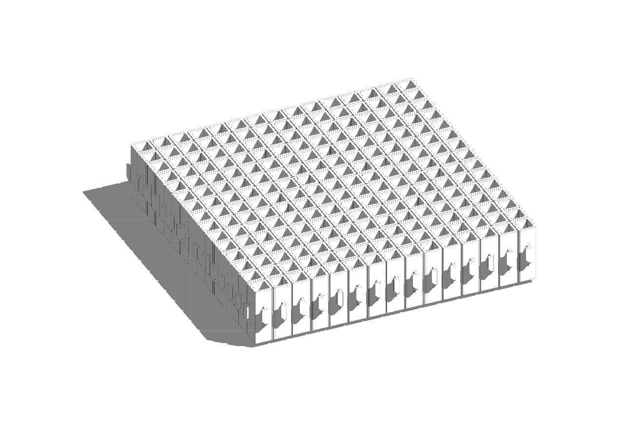
The completed grid
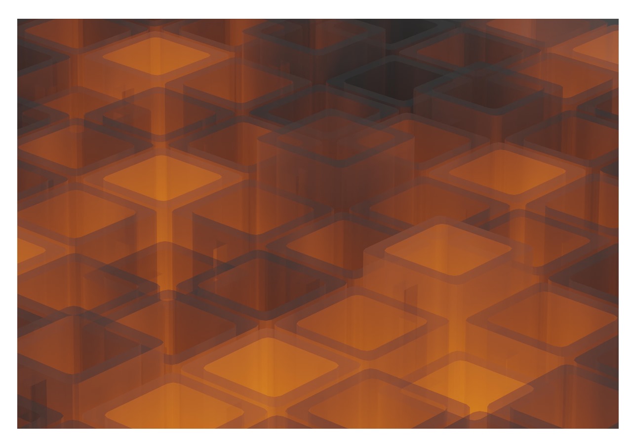
This image imagines what this might become if we were to use a transparent glasslike material, it could possibly become a lamp/ light or artistic light installation.
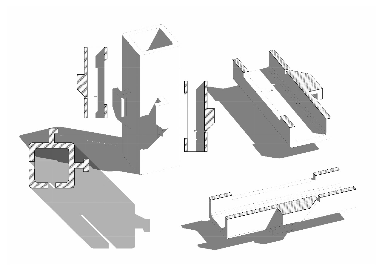
The details of a single ‘chain-link’.
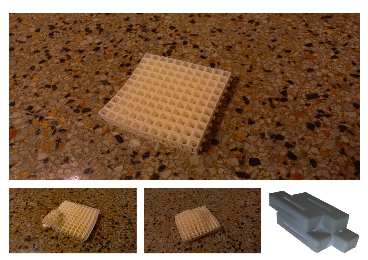
Images of the final product showing its flexibility and the test print in the bottom left corner of the image.
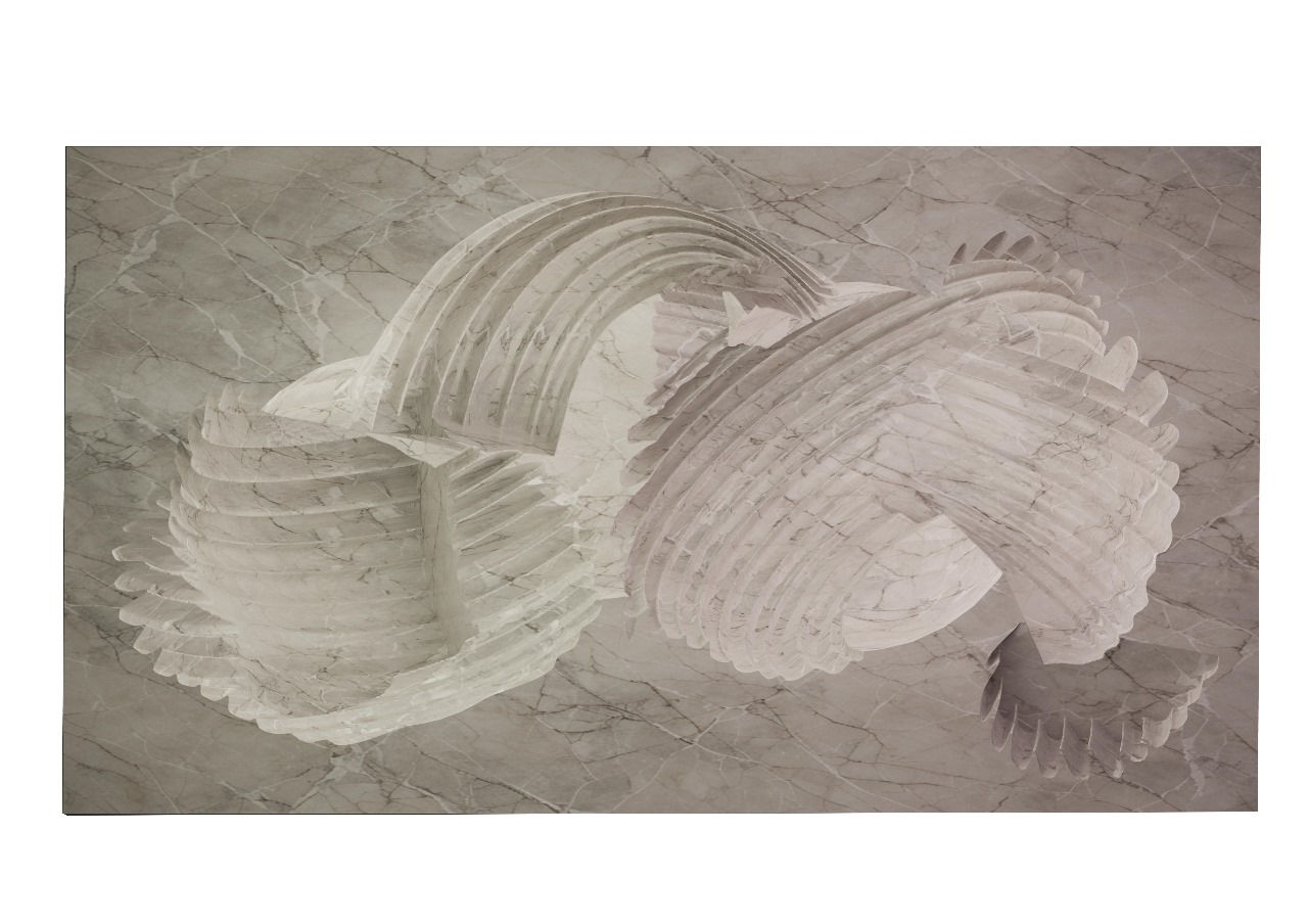
A render of the powder printed cross section
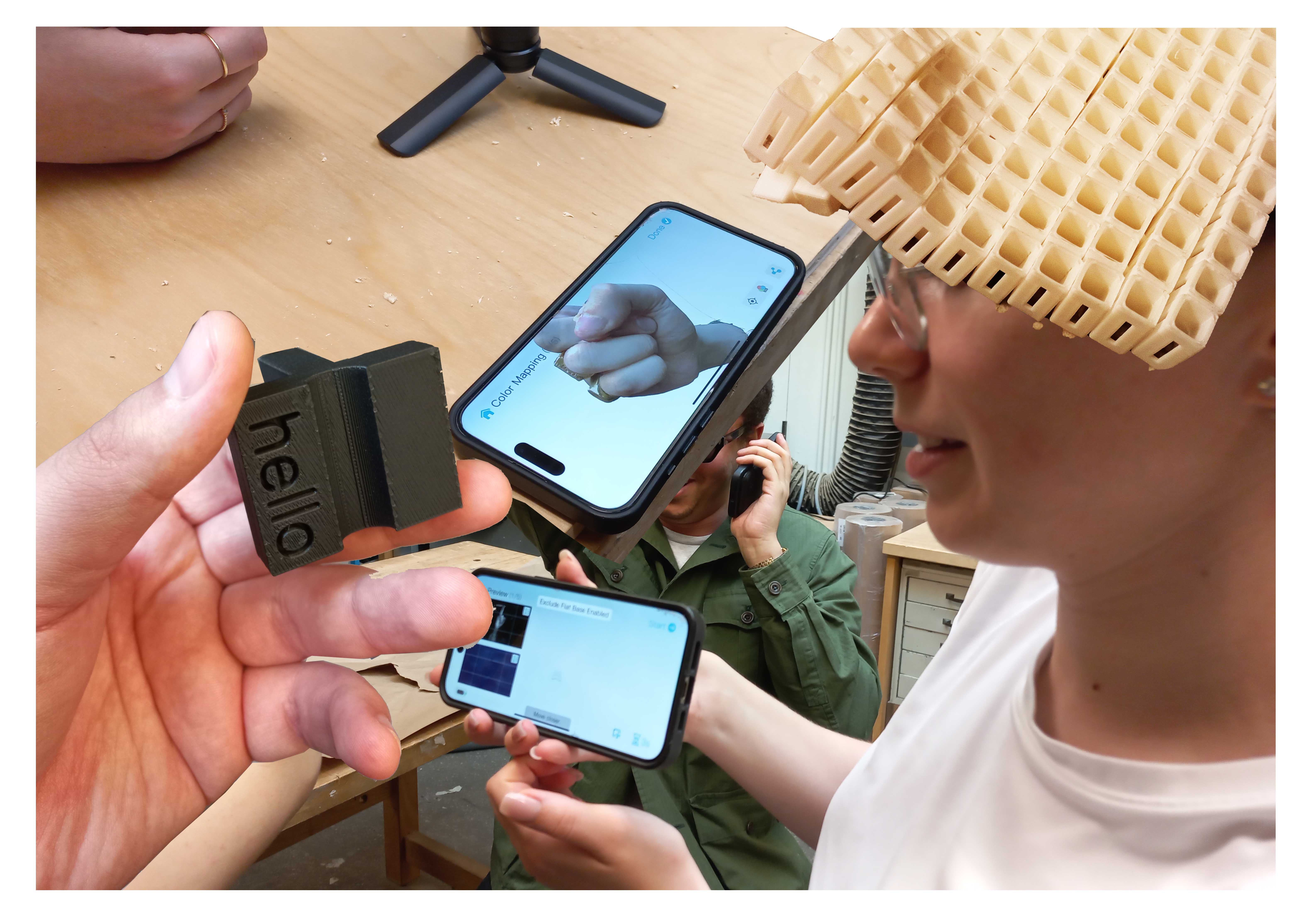
An image of the group project in scanning the hand of one of the group members
