

Networking
This week we were tasked to have a PCB board communicate with a website or between 2 PCBs.
I wanted to make a device which reads images and translates that to sounds. At this stage I was still in the process of making a sound generating machine from earlier weeks. I wanted to have this week to be a matter of having a PCB scan an image and send that perhaps to a website which translates it to sounds. I would then retrofit to the previous week to be able to broadcast this sound.
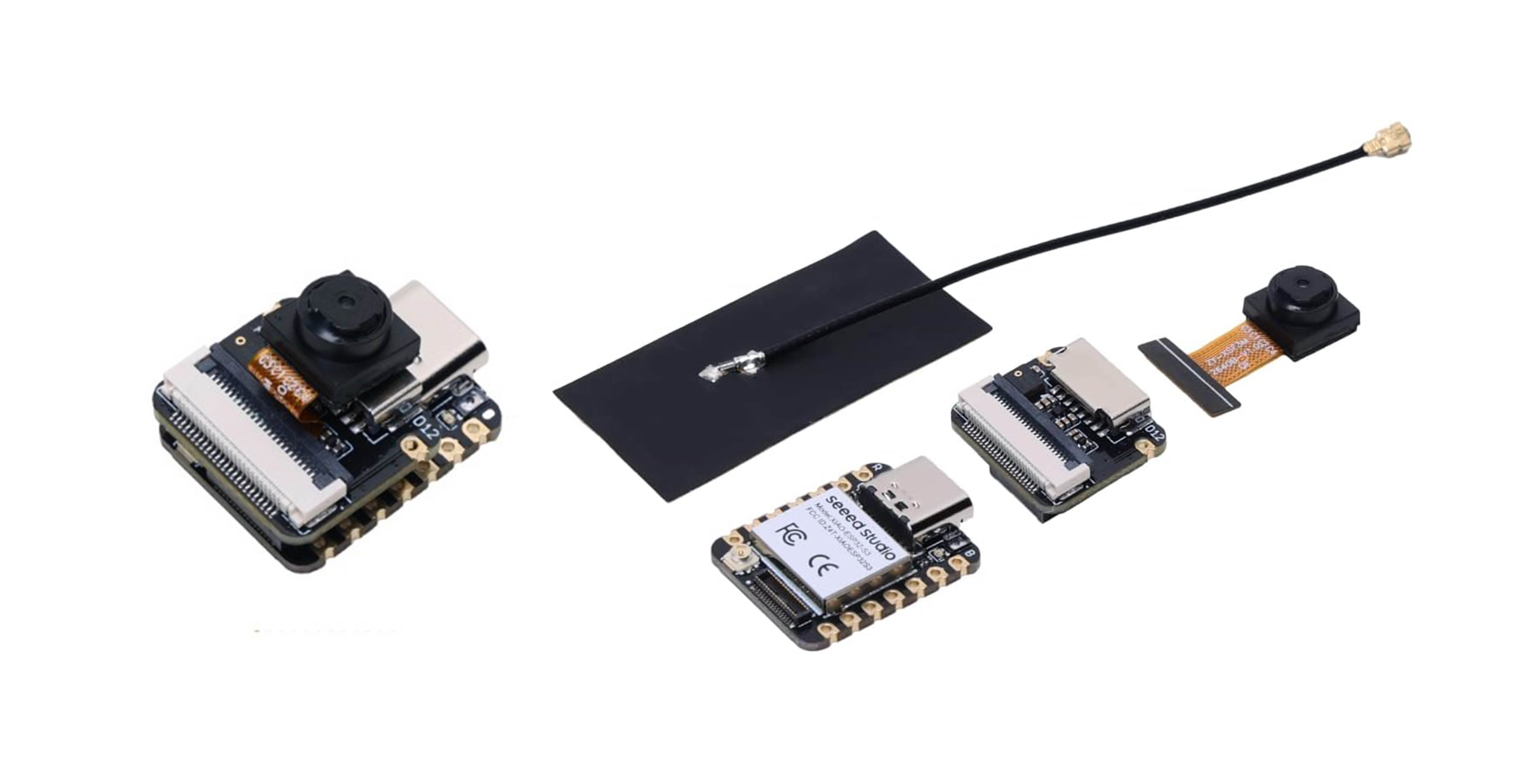
It was a bit of a challenge to get back on the horse of electronic design, but I started by re-familiarizing myself with the different types of Esp32 Xiao modules. I knew that to be able to scan I would need a module which would be compatible with a camera. The S3 sense would be perfect. Although I would need to keep in mind the design if it were to develop and evolve into another larger system.
I started by uploading the example code and made sure to check whether the code is being referenced throughout the rest of the CSS sheets. It verified correctly and then I discovered that it wasn’t working properly because the USB wasn’t functioning.
After that I ran into some trouble trying to upload the code again. The code was giving me errors and did not want to run. I then tried to run the system using Neil’s code from the HTMAA site. This was sort of a last resort at that stage and quite a long shot.
Troubleshooting
I started troubleshooting by first checking whether the correct serial port was selected. I removed the USB and reinserted it checking to notice which port disappeared and reappeared simultaneously also restarting it. I checked that the baud rate matched the serial input.
After this I followed the short video about the S3 sense on the site, checking to see that everything was similarly set up with the video as reference. I swapped out USB cables and still got the error message “A serial exception error occurred: ‘’ Write timeout - Note: This error originates from pySerial. It is likely not a problem with esptool, but with the hardware connection or drivers.”
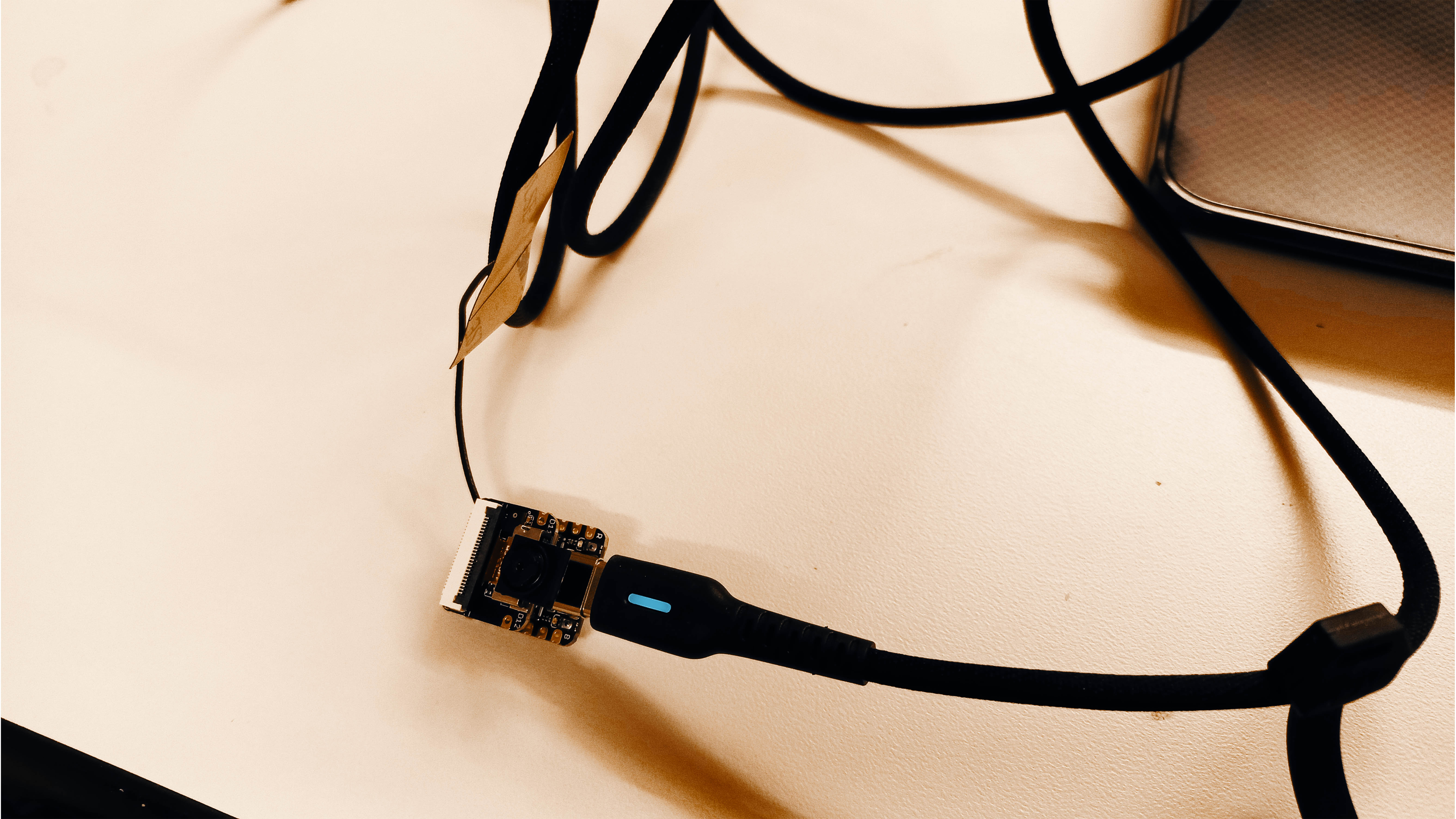
It looked like it was a hardware issue and Alec in the EECS helped me. I removed the camera unit and swapped the S3 for another one. The second one wrote, and I established that it was a hardware issue.
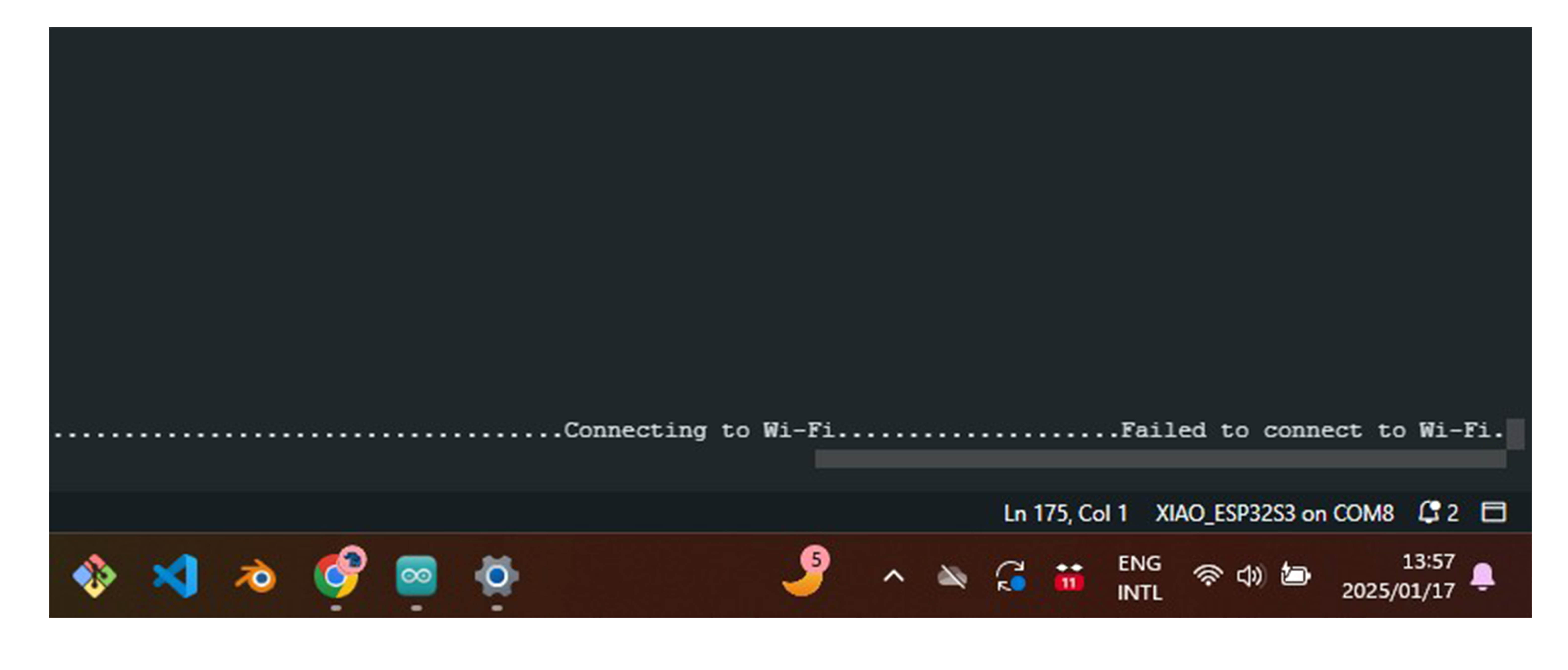
I then uploaded with the Wi-Fi module and camera attached. I found that reminding myself to compartmentalize my troubleshooting to keep deliverables to a minimum really helps. The serial monitor gave me an IP address, but it did not want to connect and kept on rebooting. Also, it gave me the message: Connecting to Wi-Fi……………. This raised my susspions that the problem could also lie with the Wi-Fi Network. The WiFi in EECS was an open network and I had my doubts about using that and modifying the code.
I connected to the normal MIT Secure network in the architecture department and got this error: E (9024) camera: Camera probe failed with error 0x105(ESP_ERR_NOT_FOUND) E (9024) gdma: gdma_disconnect(238): no peripheral is connected to the channel
After which I ran a camera test to try and see whether or not the fault lies with the camera or the connection with the camera. It gave me this error relating to the camera compatibility: C:\Arduino\Cam\camxiao\camxiao.ino:7:10: fatal error: camera_pins.h: No such file or directory 7 | #include "camera_pins.h" | ^~~~~~~~~~~~~~~ compilation terminated. exit status 1 Compilation error: camera_pins.h: No such file or directory
Troubleshooting 2
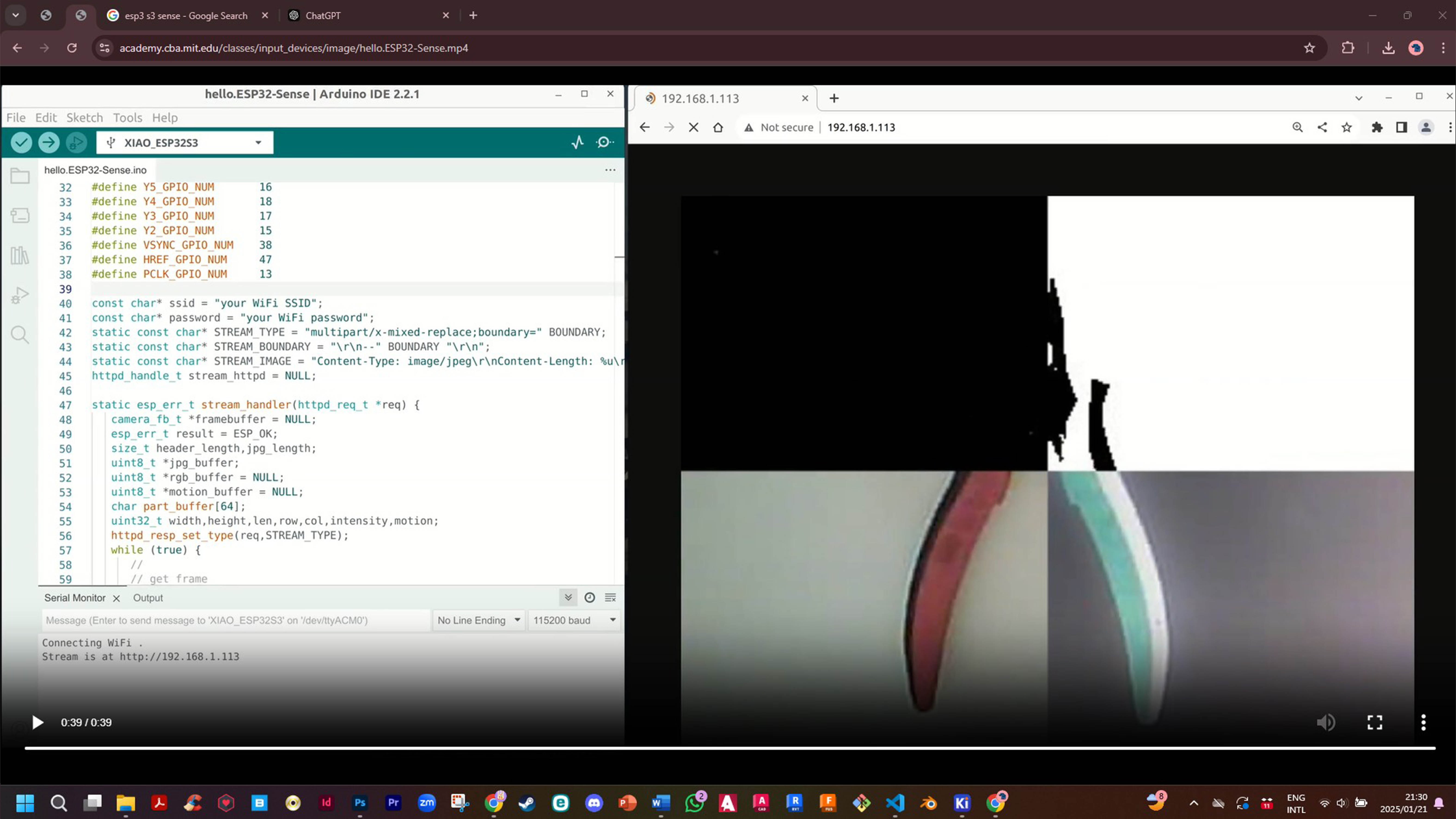
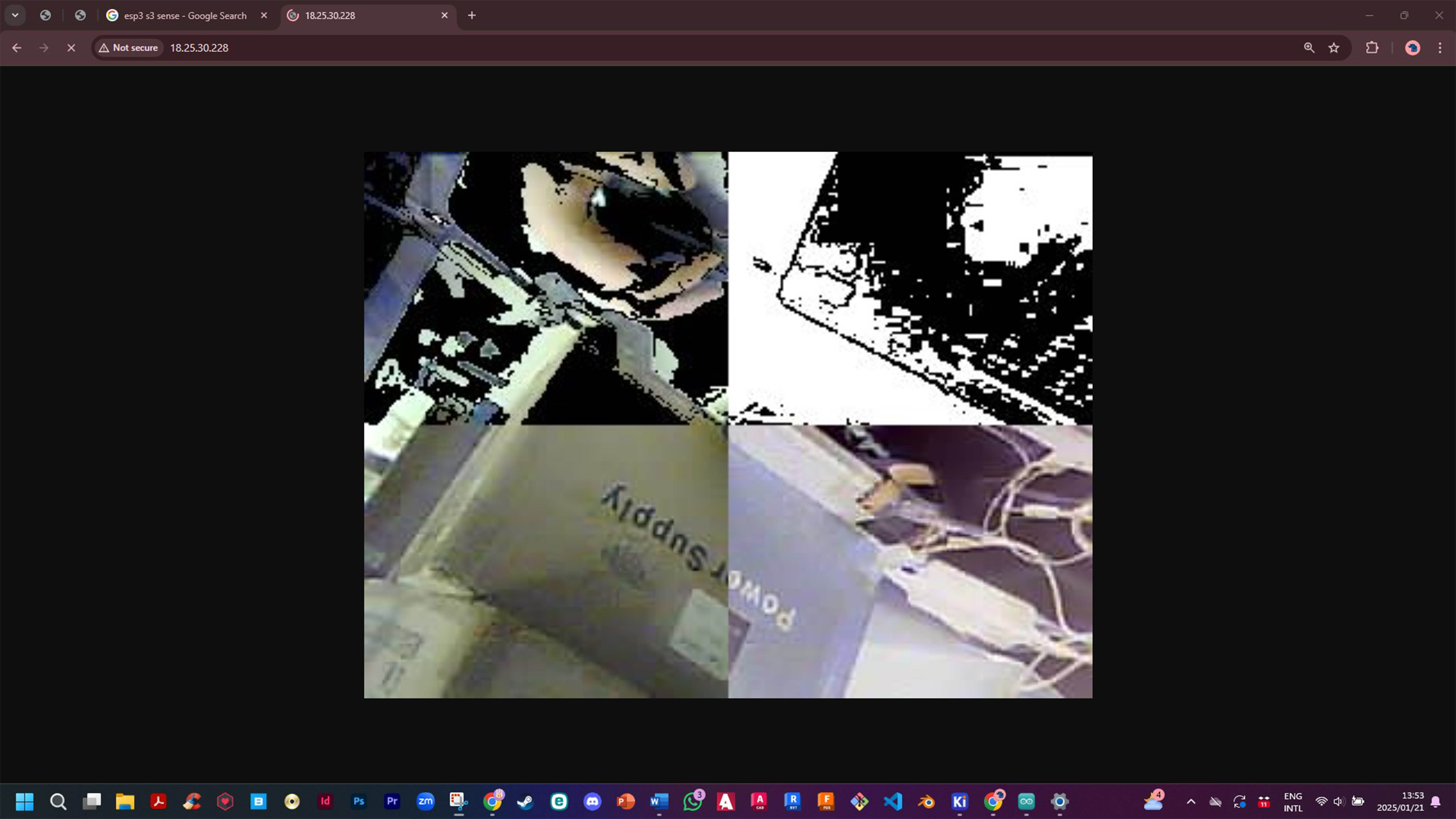
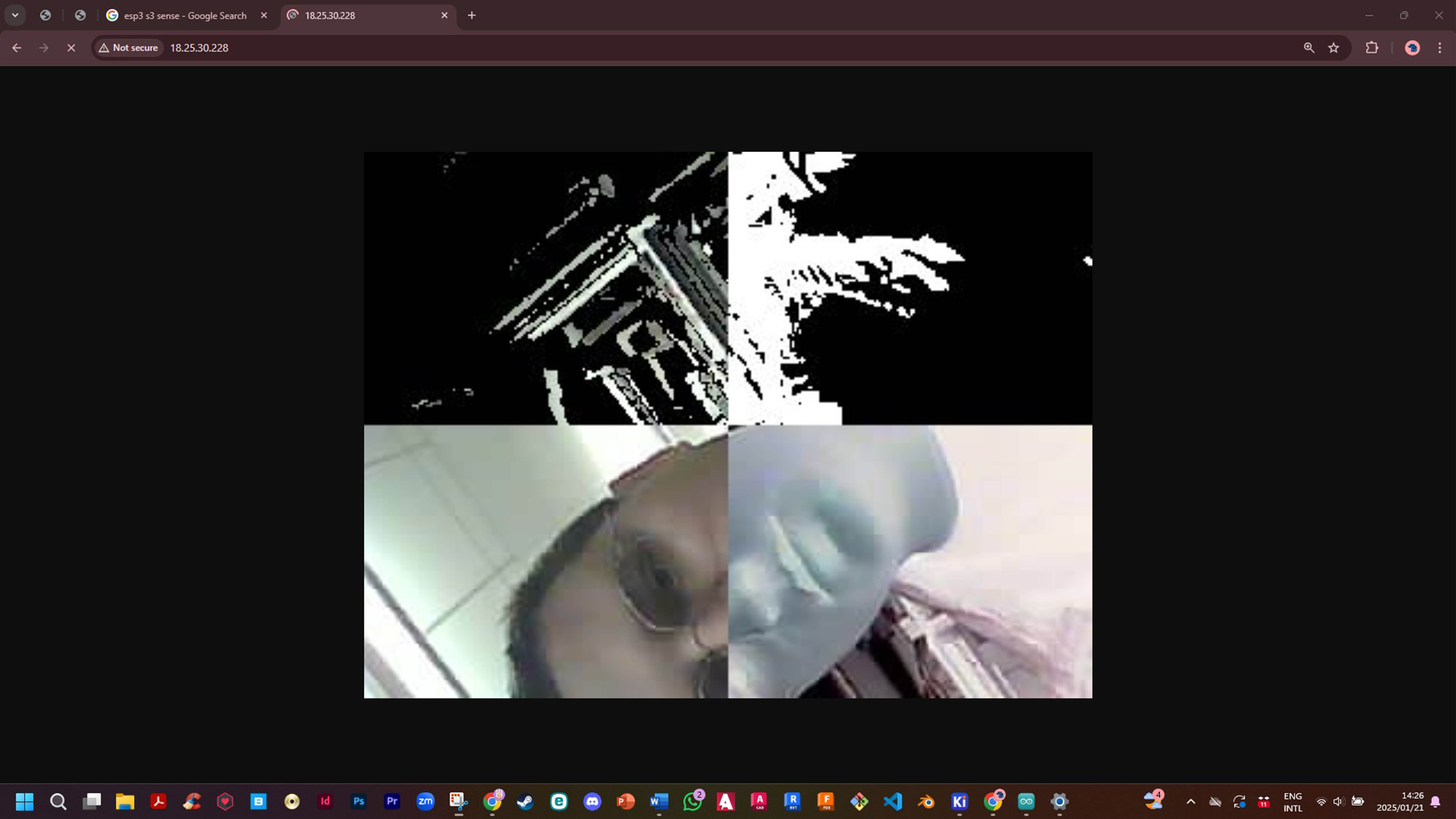
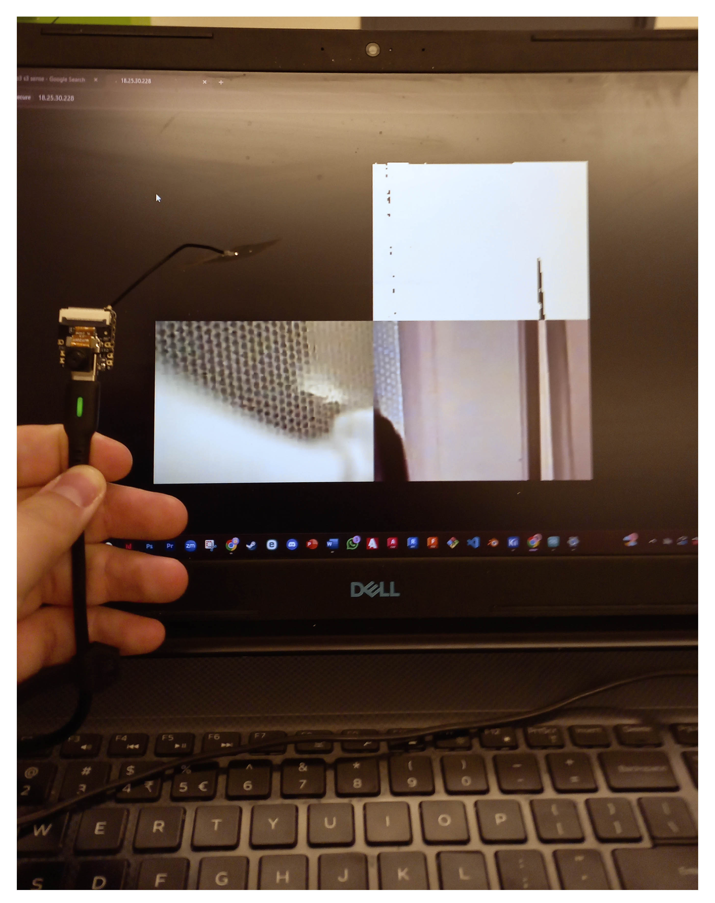
I came back a few days later and tried to run some debug tests on the S3. It still gave me many errors and then I consulted the massively helpful expertise of THE LEGEND aka Anthony! We troubleshooted the XIAO and then started by using another WIFI network. Anthony said that the EECS_Labs WiFI was on a 2.4 and 5 GHz network and that may cause problems. We used the "608_24G”, a new XIAO and a new USB-C Cable which eventually helped to visualize the stream.
Camera and Site integration.
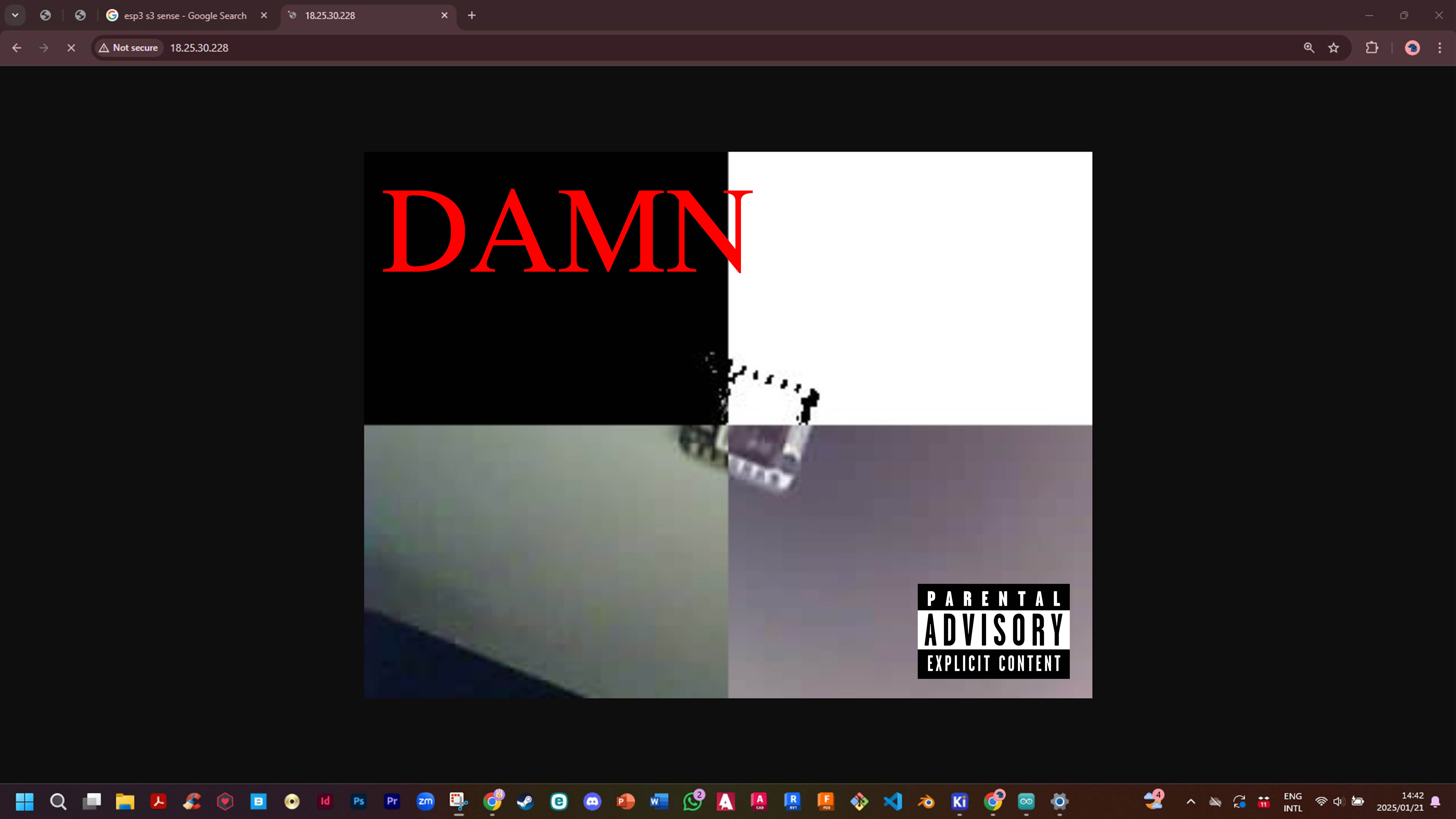
Workflow