Final Project — Sensitive Nightlight

Inspiration
For my final project, I'd like to make a night-light for grownups.
I would love to not turn on every single room light as I journey from my bedroom to the kitchen for water in the middle of the night.
However looking online, I'm not really seeing anything that looks visually nice.
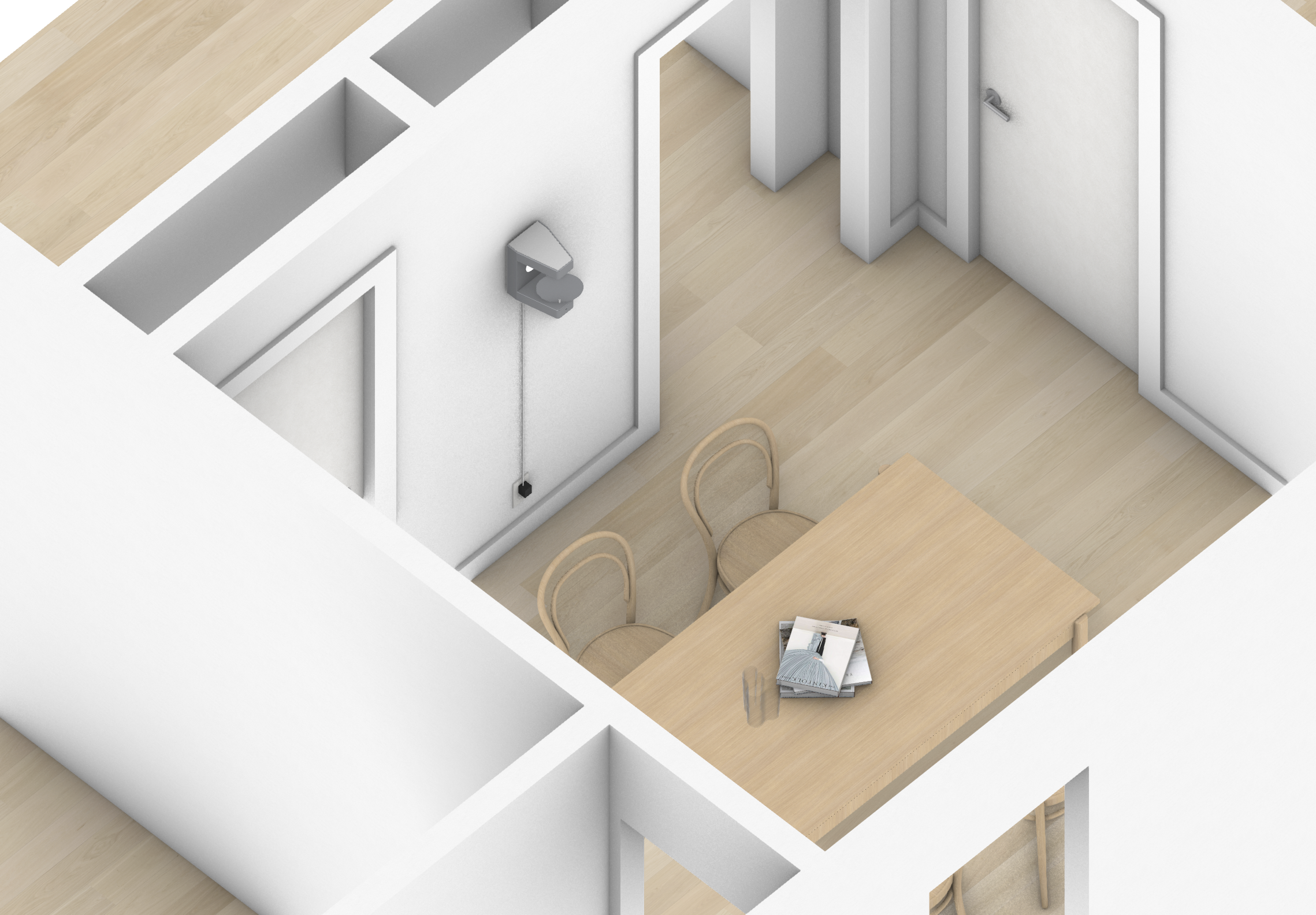
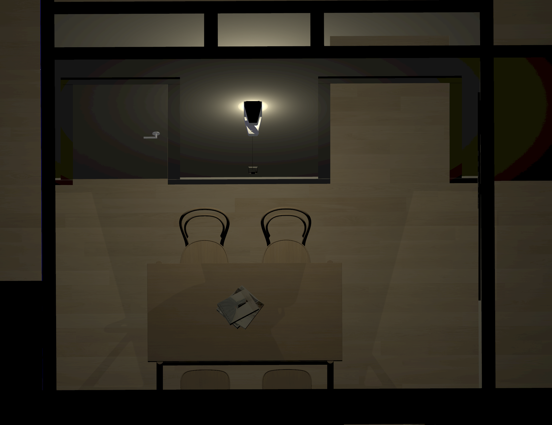
Not really like this...
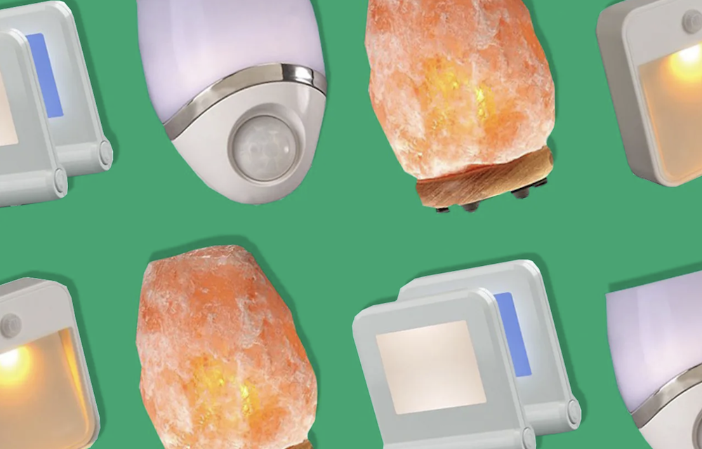
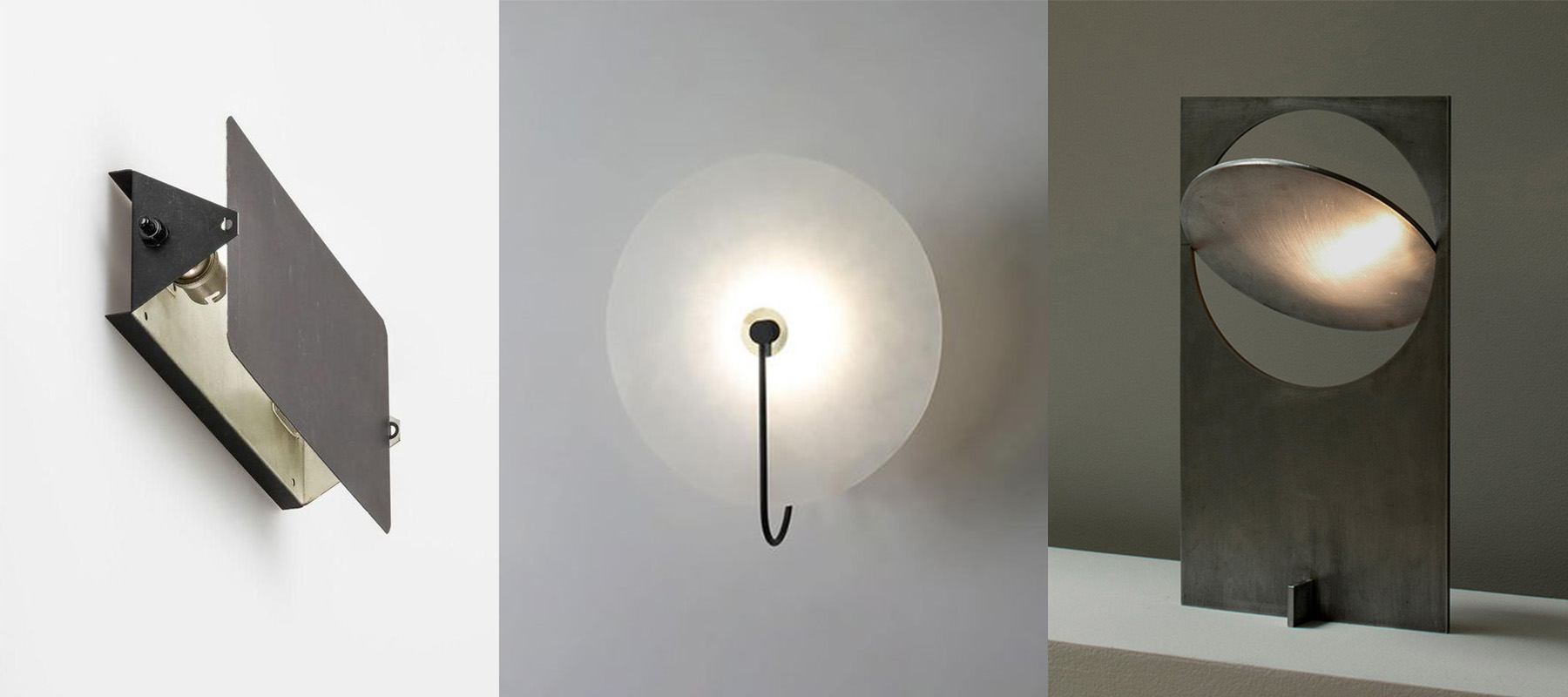
More like this...
My idea has two parts (using the spiral development method and if I have enough time to complete items). Part one is to have the light brigthen or dim depending on the distance of the person to the light. There should be no need for on/off switch controls.
The second part is having the "fin" rotate depending on the location of the person.
Concept
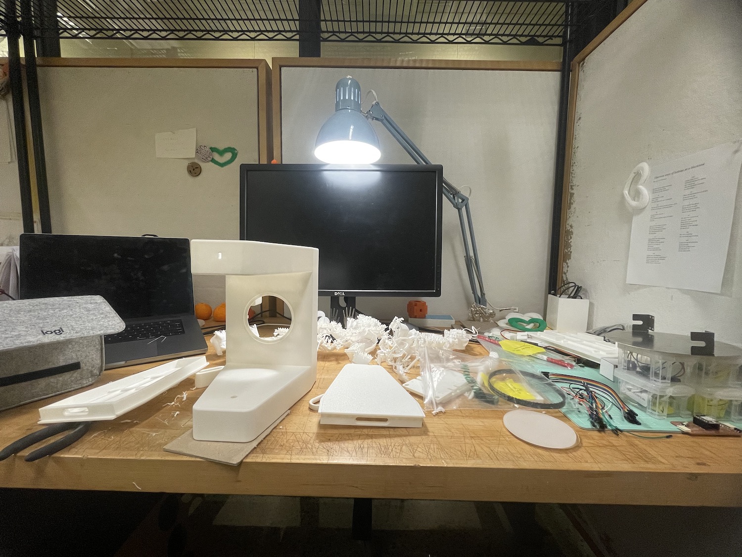
After looking over some references, I started with basic blocking and general vibes of the project.
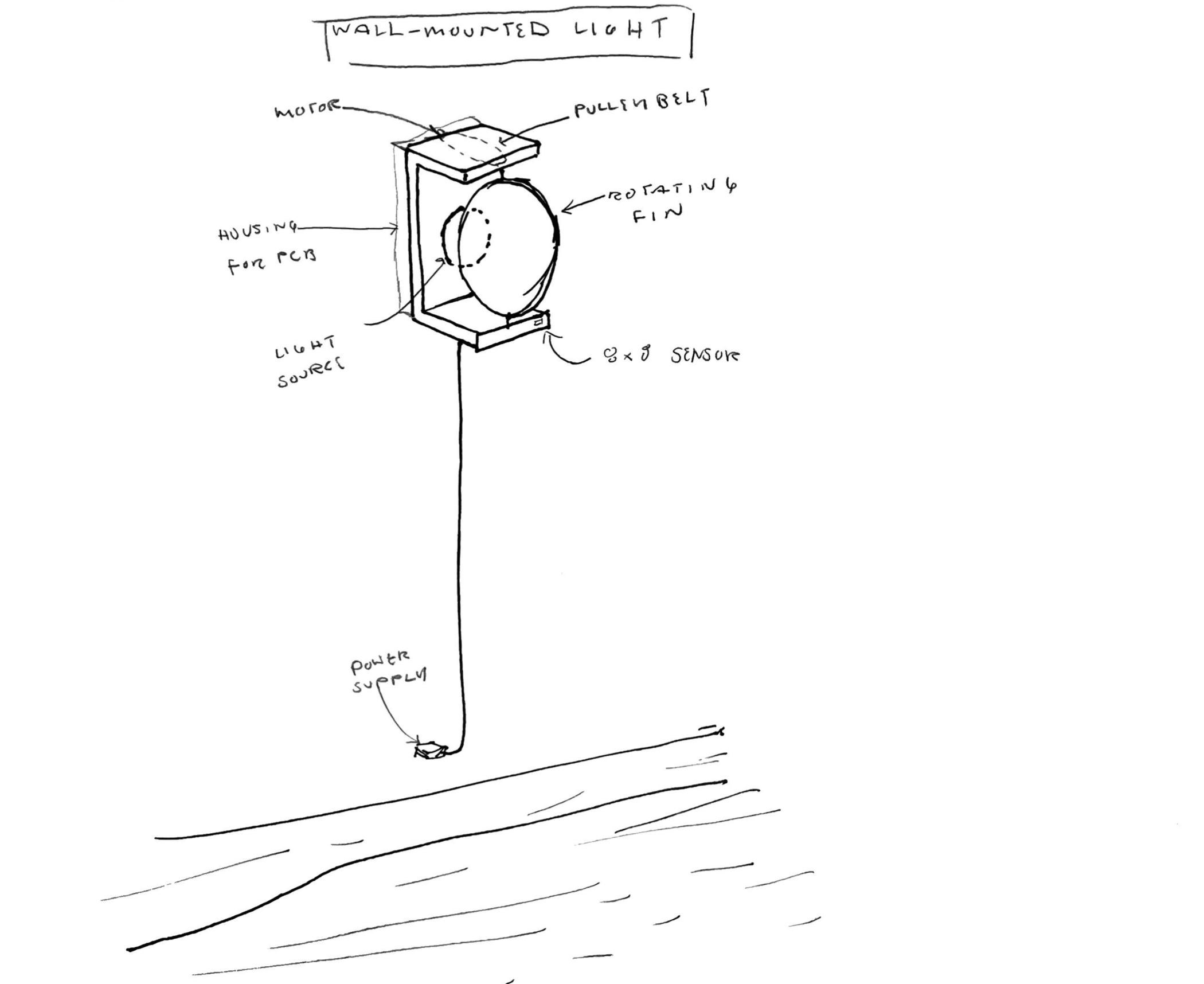
After a few weeks, I made a sketch to get the system/parts/ and overall input and output devices developed.


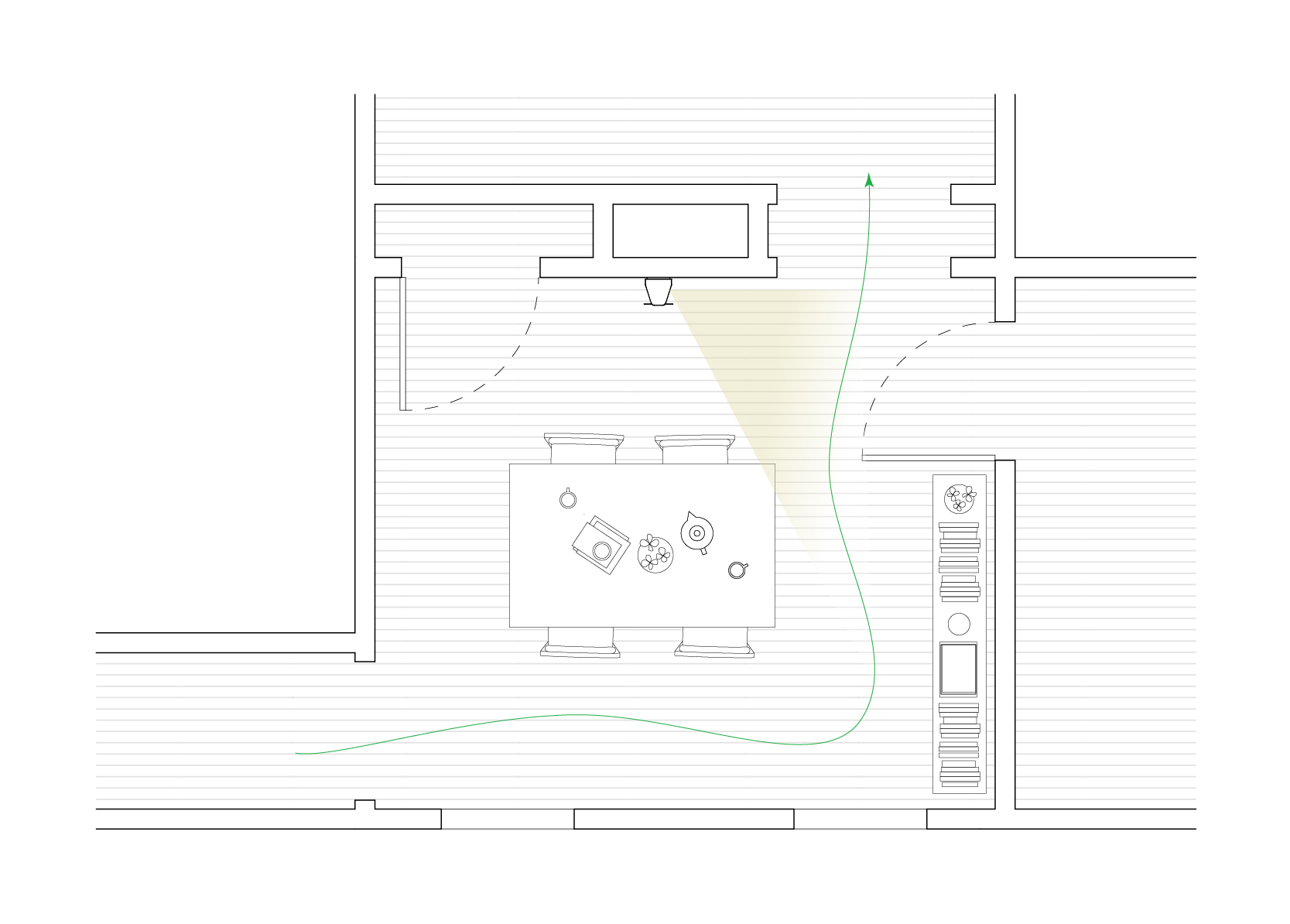
I wanted to design the piece based on the context of my apartment. The layout of my place is a bit weird, with no hallways and the rooms all connecting with one another.
Another issue is the the flush mounts on the ceilings all have pull chains, and not switches, so late at night turning the corner
I trip over myself. The idea is that my lil lamp tracks my movements, making sure I'm always lit as a walk by.
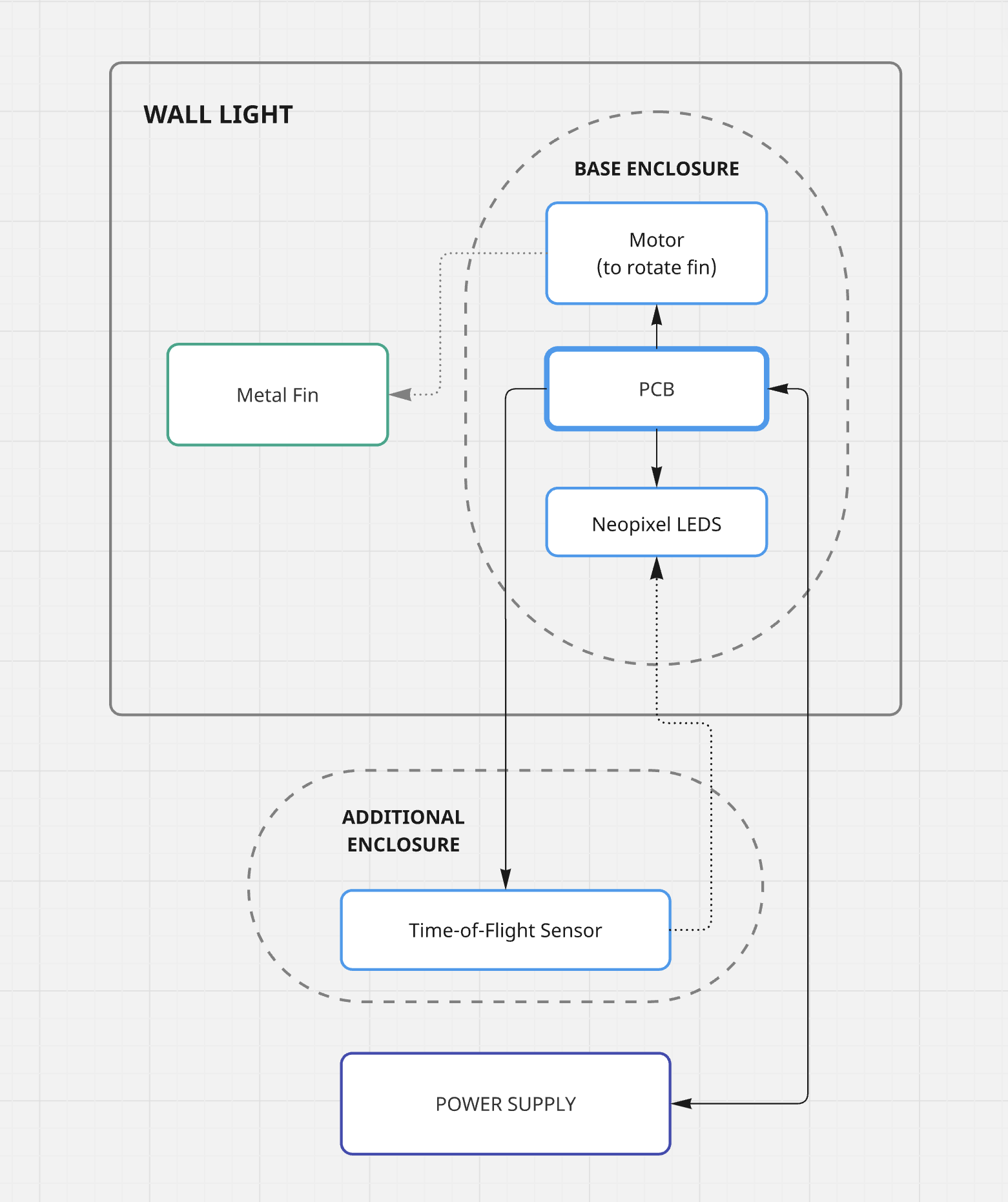
System Diagram
Weekly Updates and Schedule
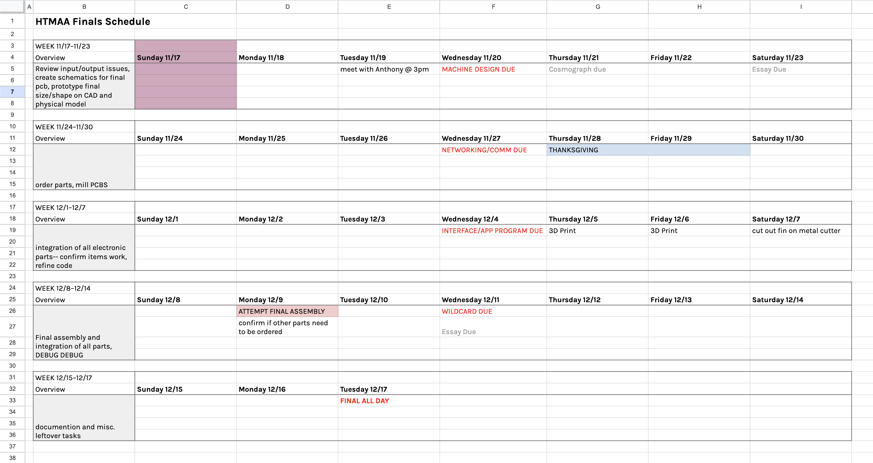
I did a lot of the work in parallel with eachother so I broke down the process by each section of the project!
Input/Output/PCB Design
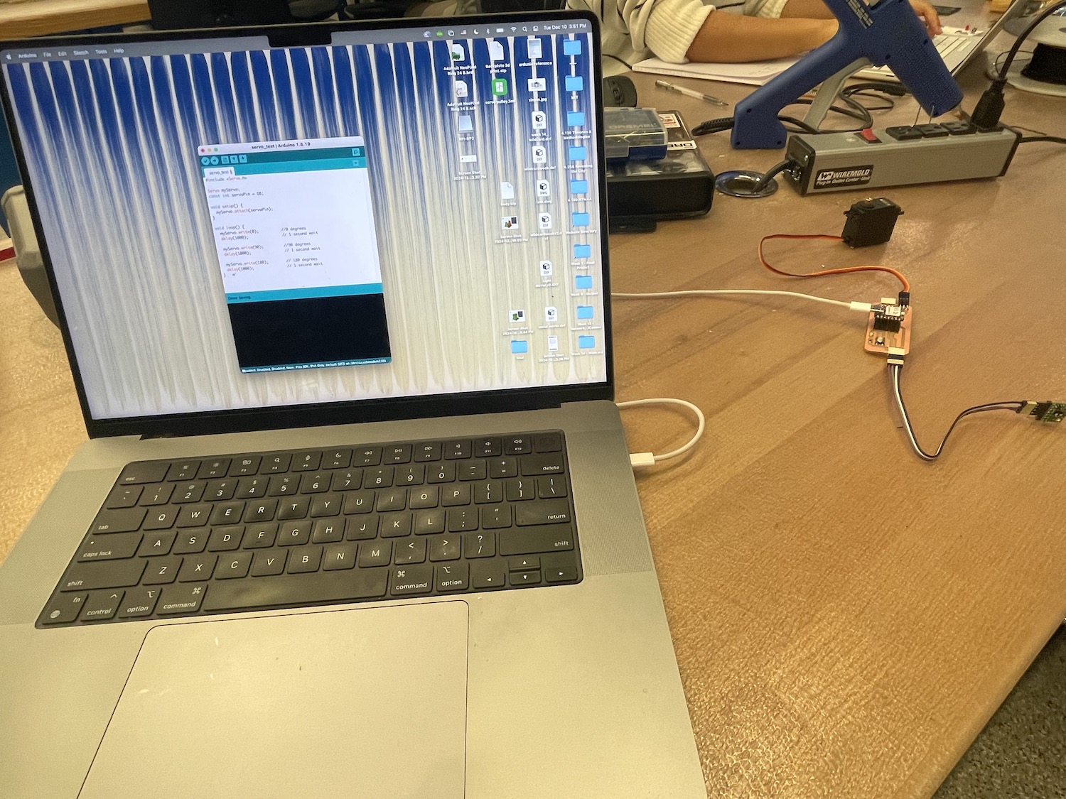
After output week, I needed to visit Anthony to figure out why the servo would stop moving.
I assumed it was a power issue but wanted to double check. After a few minutes of playing around with the code,
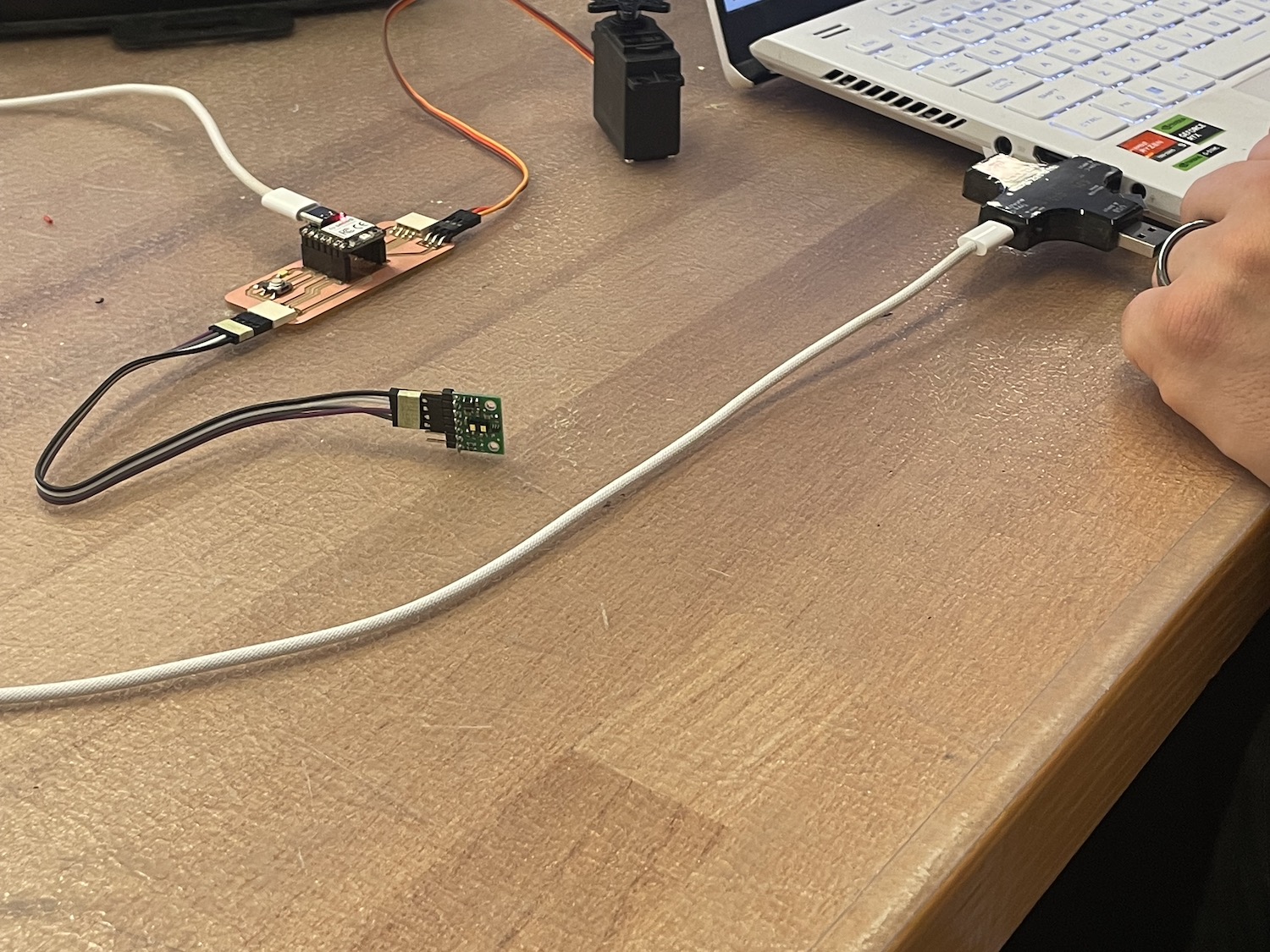
Anthony used a little amps reader to test the servo in both the standard size and mini size.
He said that while the microcontroller should have enough to power the servo, plugging it into my computer cuts the line. Hence why Arduino struggles to find the serial port afterwards.
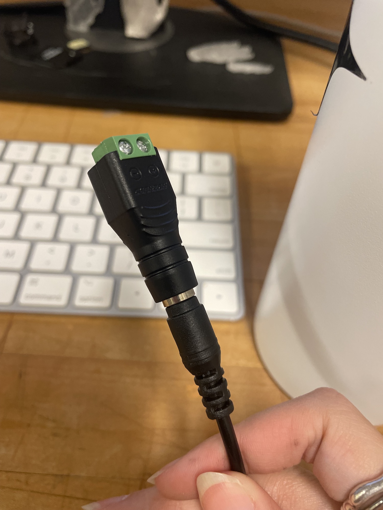
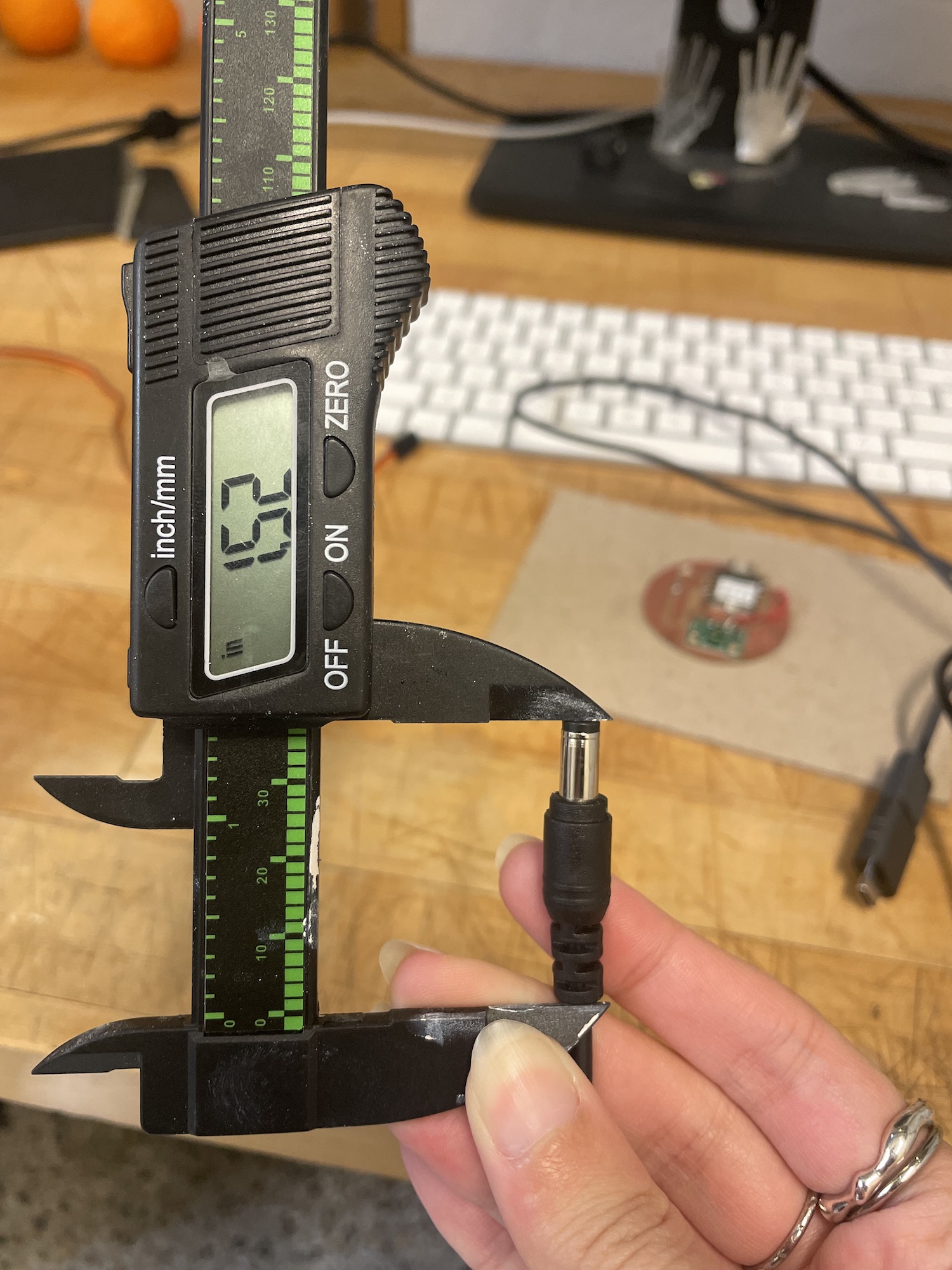
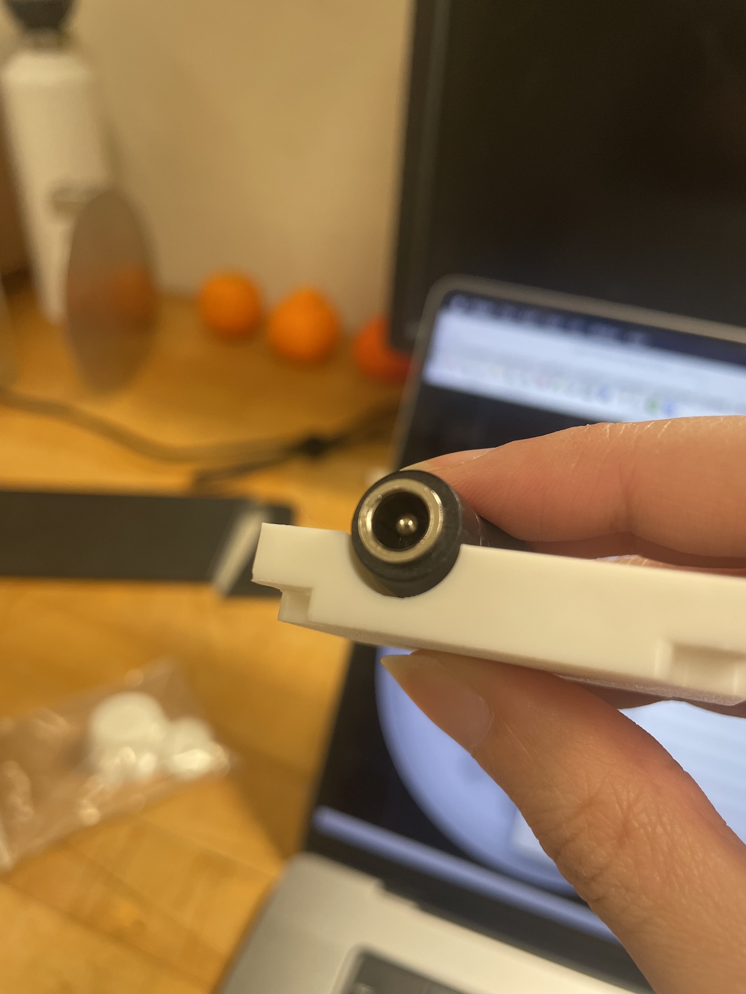
I decided to add an additional 5V power line using a DC jack.
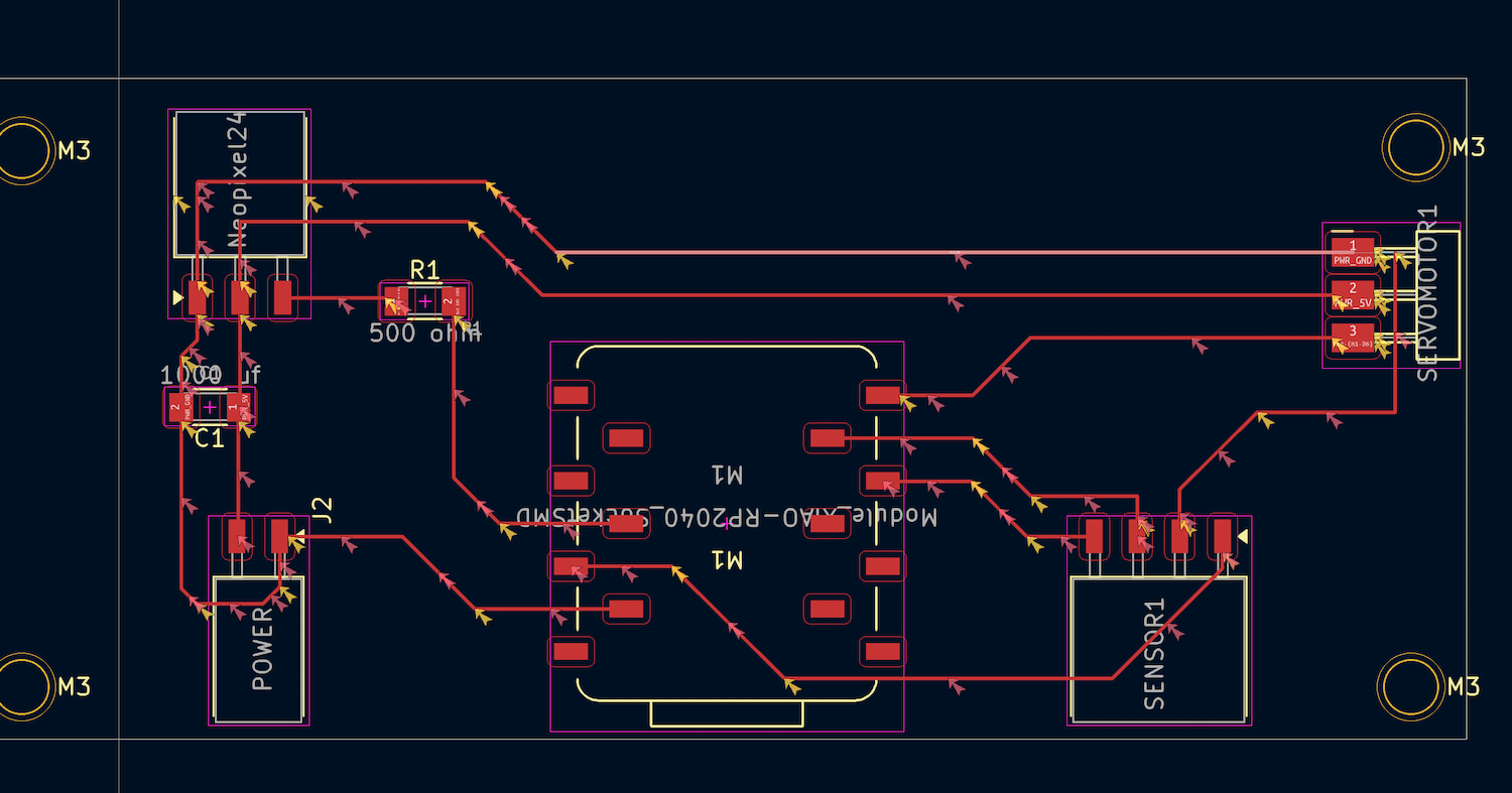
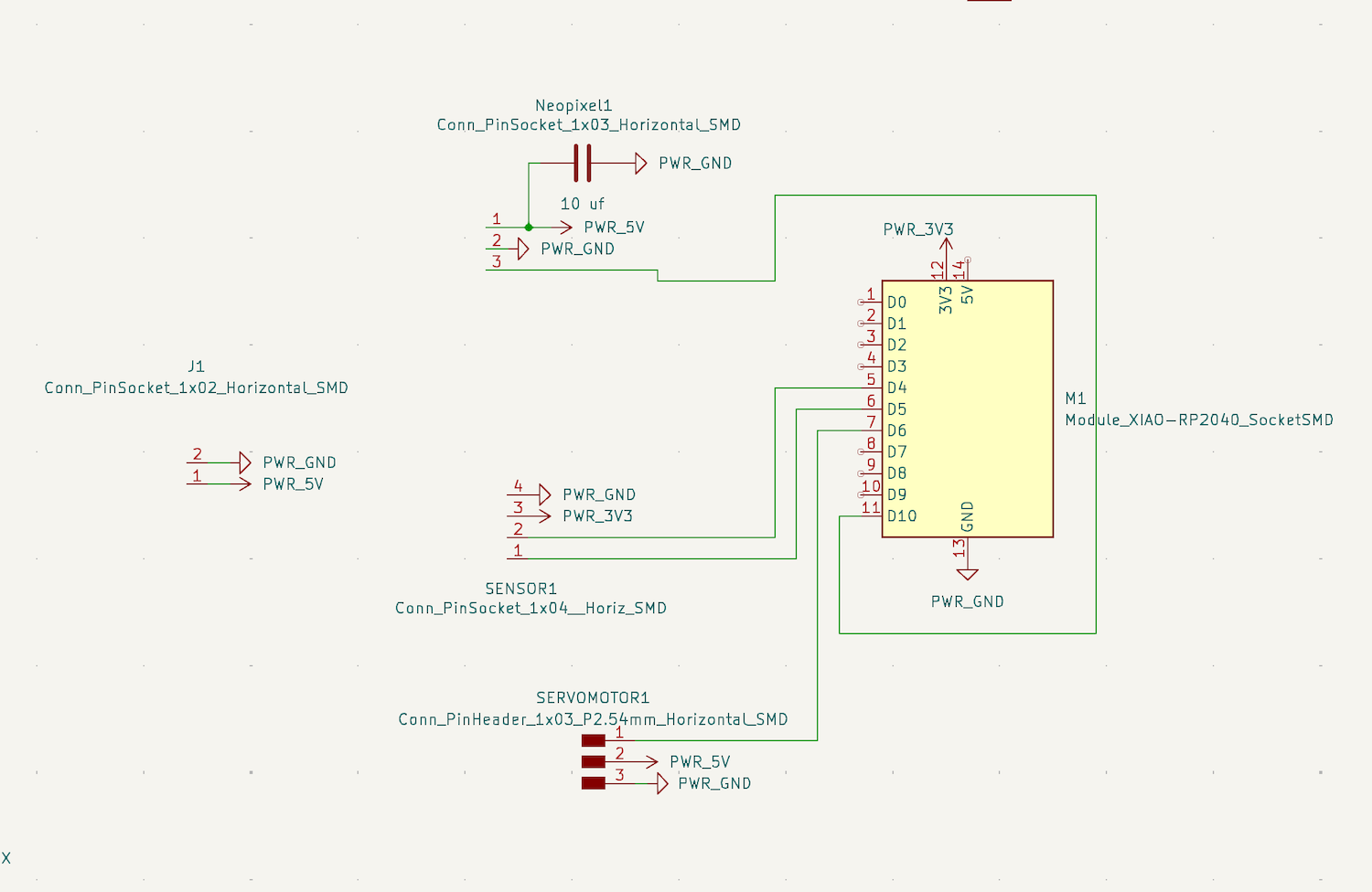
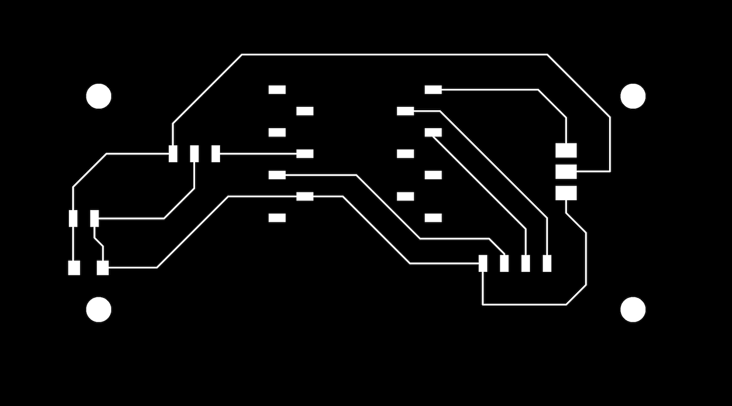
Using input and output week as a launch pad and chatting with Anthony, I went to develop the file board for my project.
Using connectors for each component, the idea was to be able to plug and play with the board, as well as noting if any part failed, I could easily swap out a piece.
Anthony reviewed the board and said it was fine, besides noting I may not need a resistor from my LED to the microcontroller.
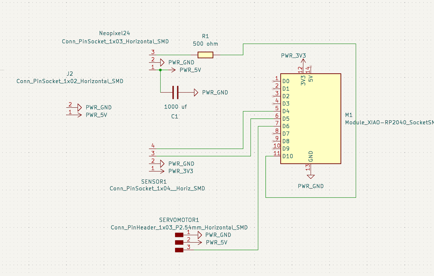
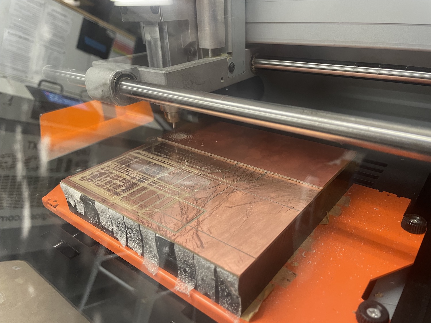
I added in a O resistor just in case. And so I got to milling!
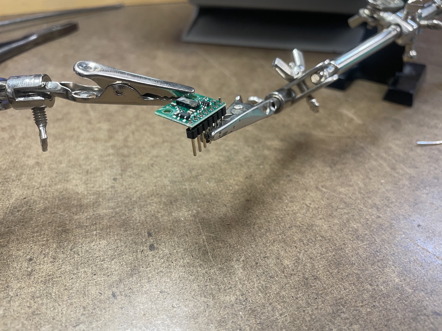
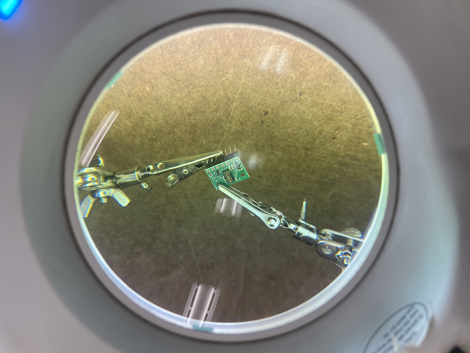
The soldering process I thought I had but I was really struggling. I realized I was using lead-free solder this time... I recommend the lead if you aren't consistently soldering and turn on the fan.
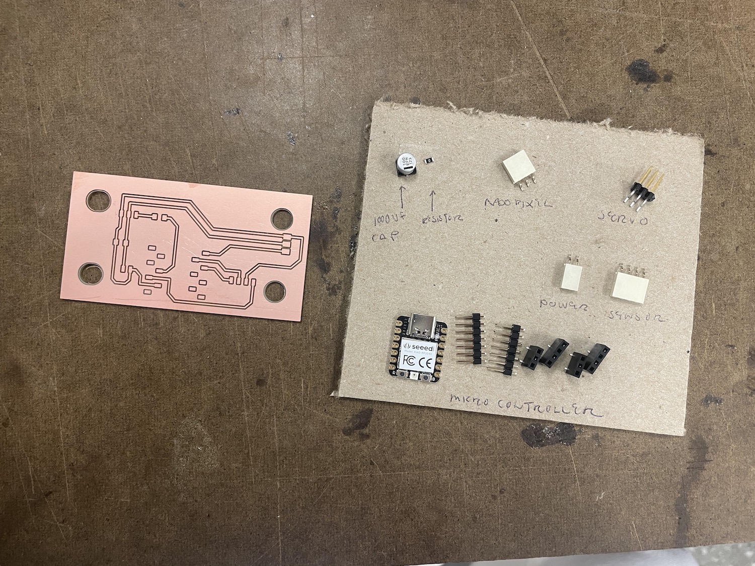
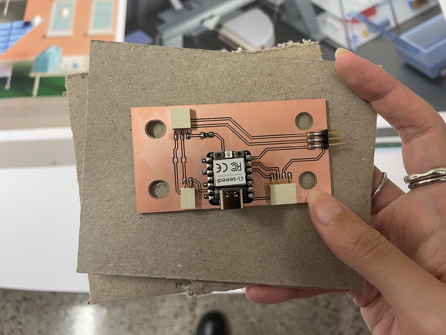
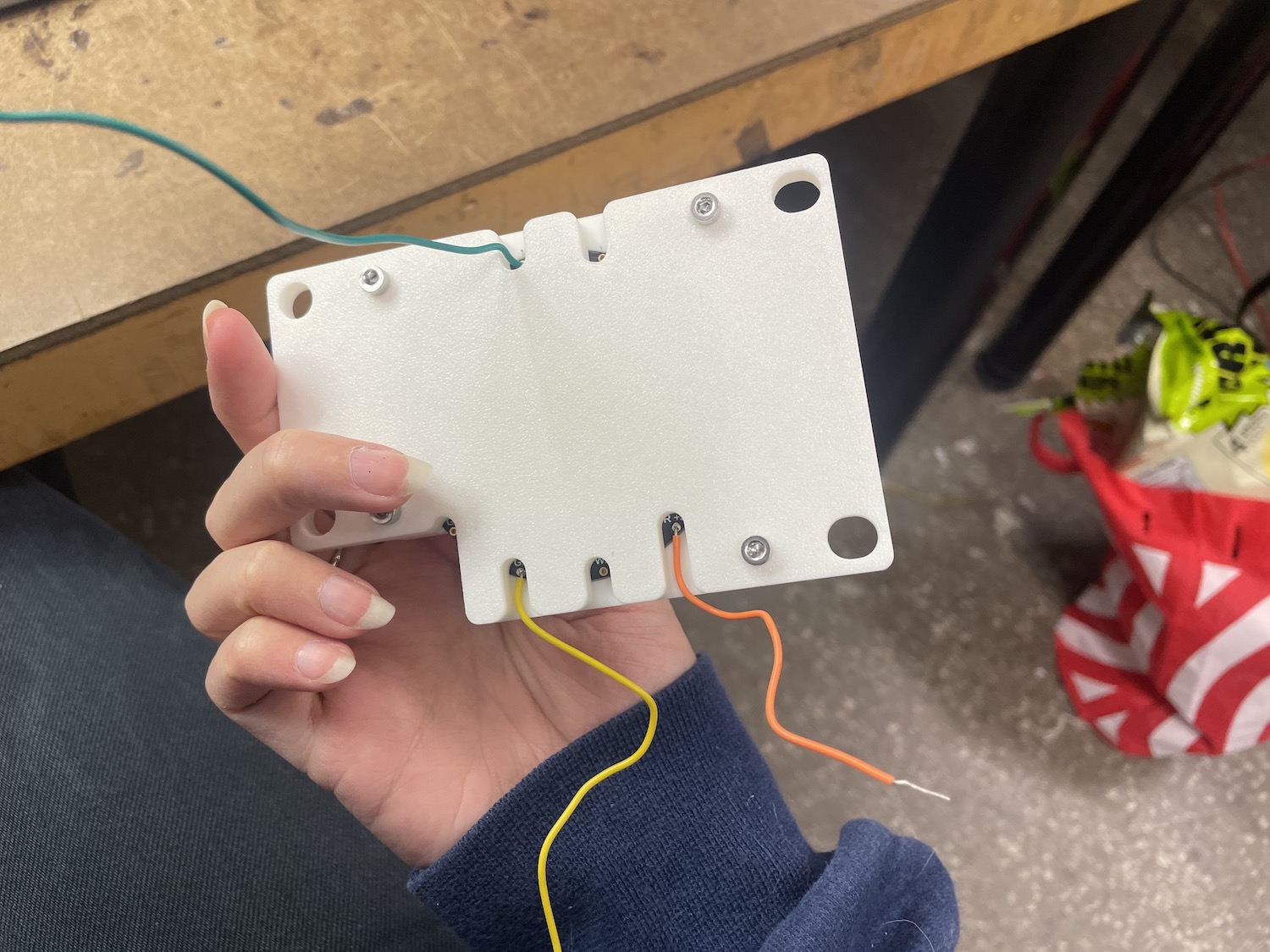
I realized my first mistake.. the connections to all my parts were slightly in the wrong location, making it really hard to turn the cables to plug in.
Bcause of that, it was unable to fit into my mount. It was also sitting really low in the mount. At this point, I had to go on with the testing and integration, knowing I'd need to redo the board.

Couple days later and I made some adjustments to the board, including shifting all the connectors in a bit.
For next time, I would swap to vertical connectors but it looks good sitting in the board.
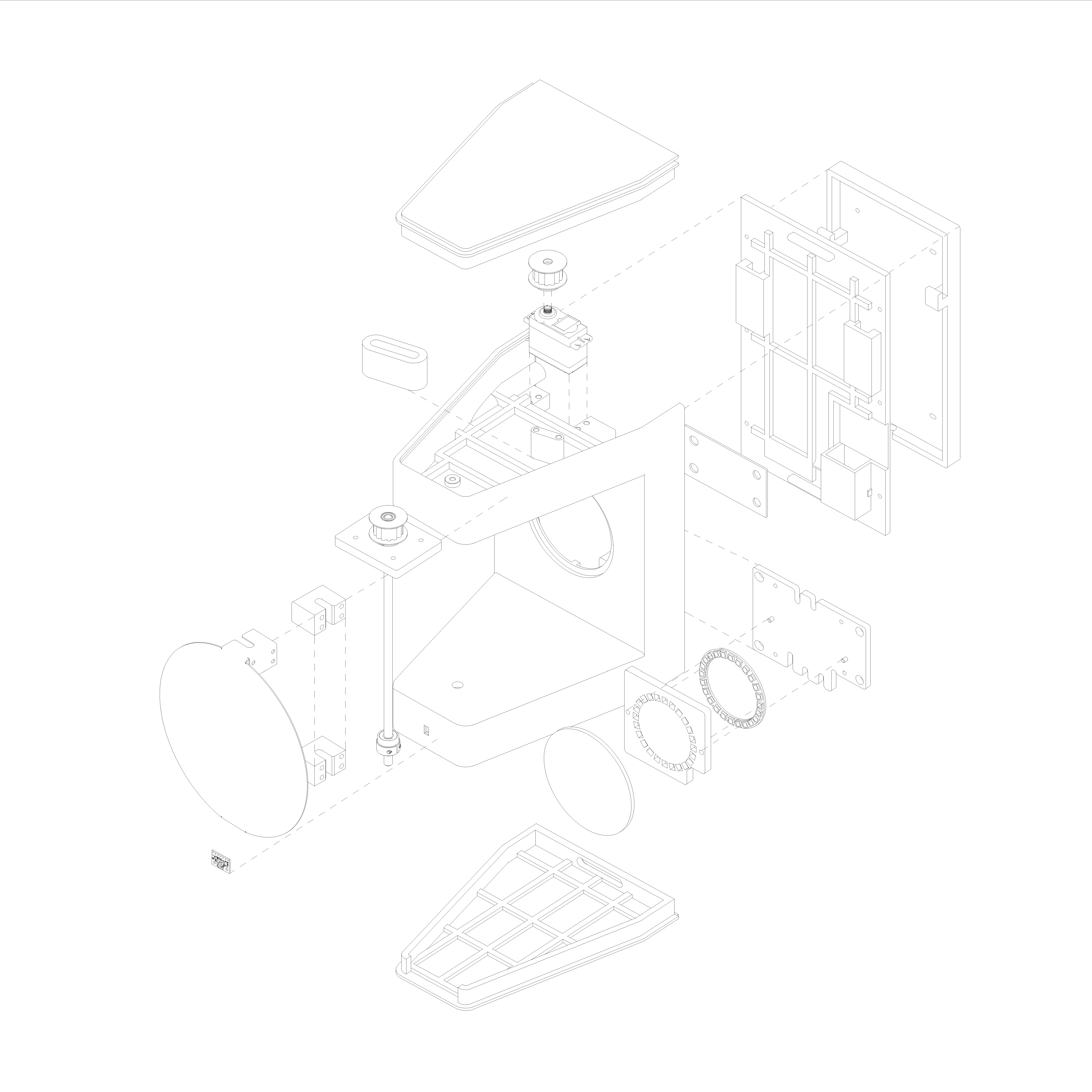
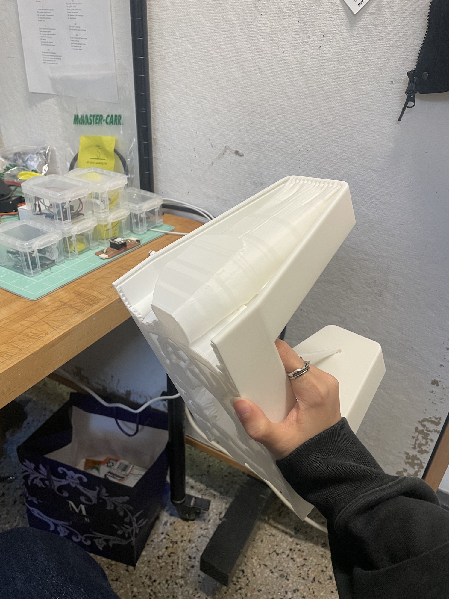
Main Body
For the main body, I started with the orginial sketches as a baseline.
I consulted my Mech-E friend to best develop something that worked on clean cable management in a tight space.
The original design was a bit more squared off so I tapered the ends that held onto the fin.
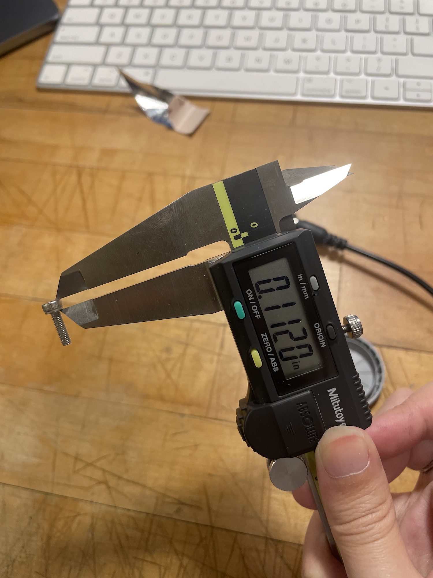
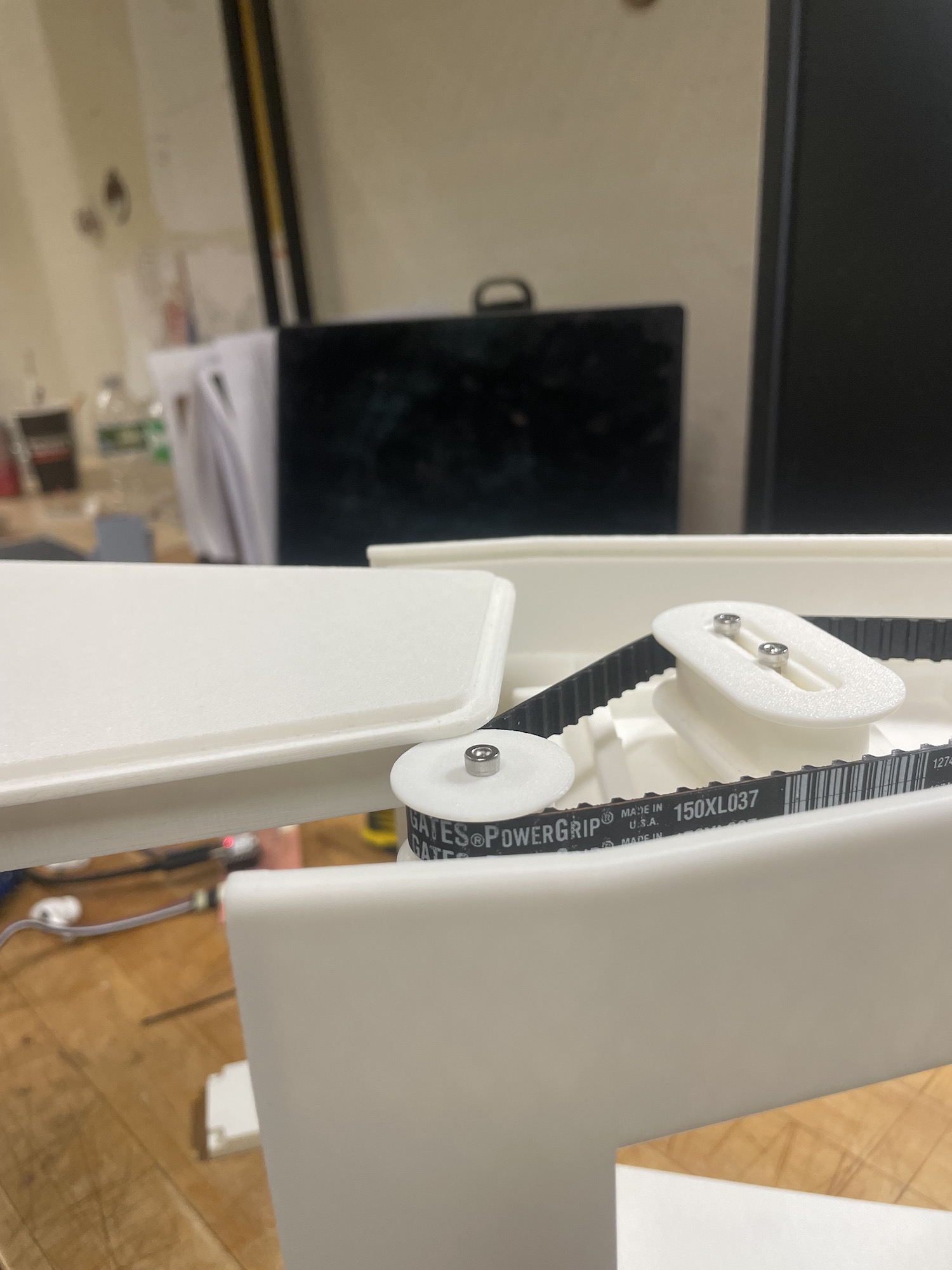
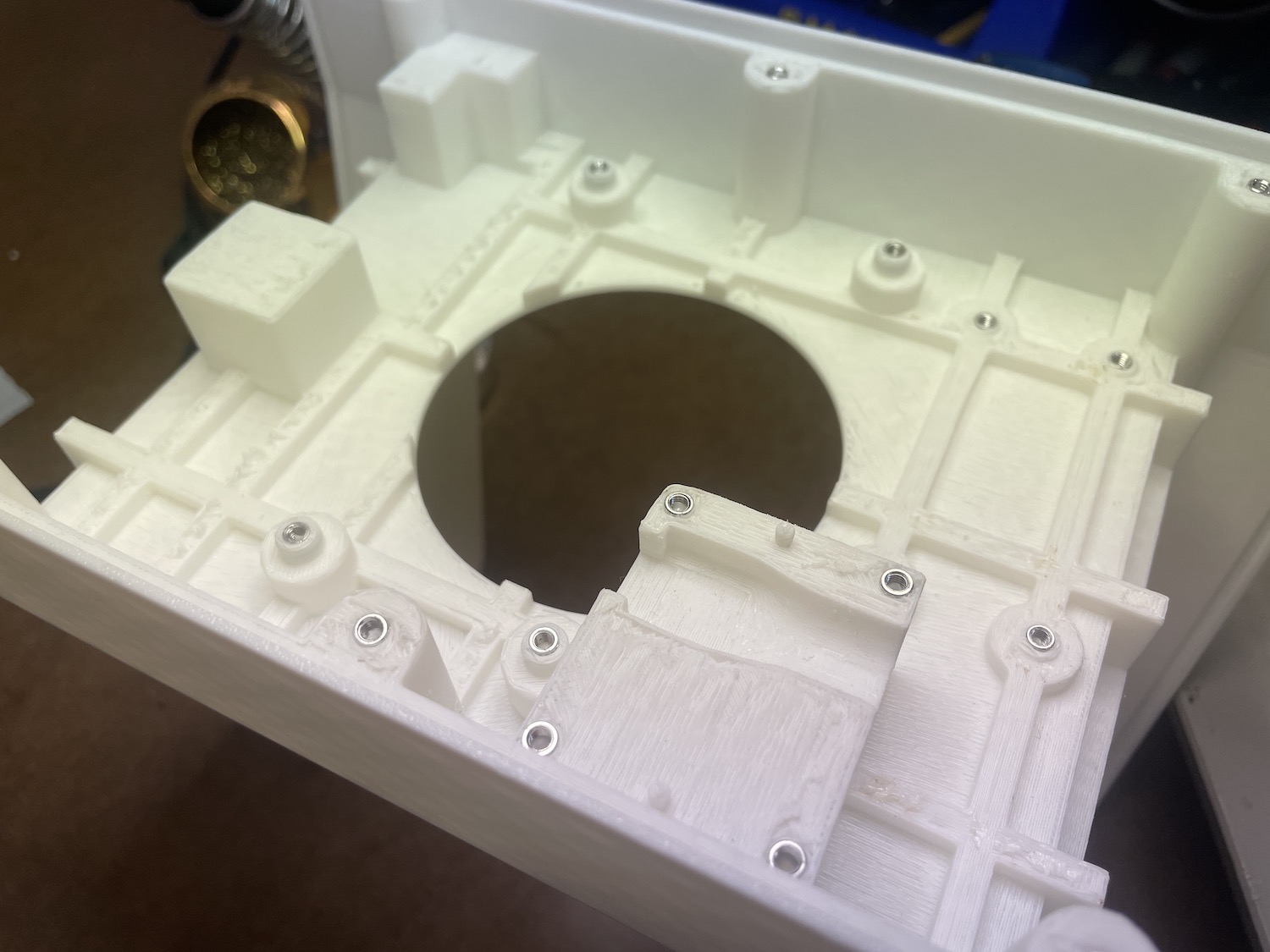
From there, it was a lot of trial and error for the parts to all fit together with both the pulley belt and servo, LED ring,
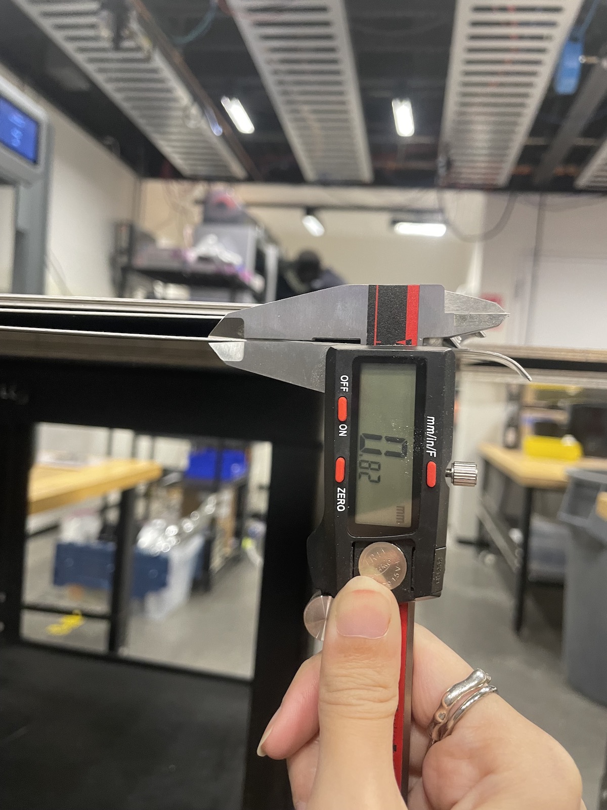
sensor, and PCB all held within a 1.5" thick base. I wanted the individual parts to each have specific place, so I used the caliper a lot during this time.
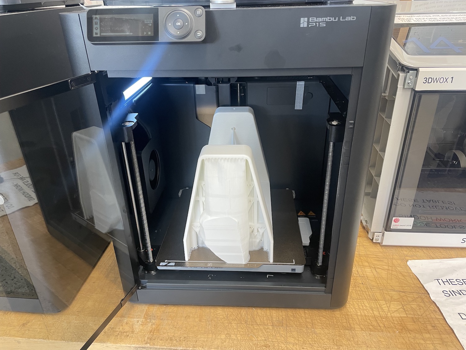
I started printing the parts early as I was afraid the machines would be full during finals time. The main body shell had to be sized by the limitations of the bambu (256mmx256mmx256mm).
I learned quickly that while they market the printer with those sizes that in not the case. I think roughly, especially if you are printing supports the limit is 248mmx248mm.
The print was originally going to take 29 hours with high quality... so I went back to standard print which ranged from 15-18 hours depending on rotation.
I struggled with the supports as the slightest shift made the shape to big. Finally I put the print in.. only for it to fail 2 hours in.
This stressed me out a bit so I waited a bit longer for the second round to make sure everything stuck to the bed.
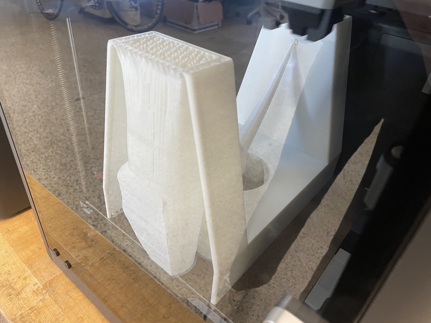
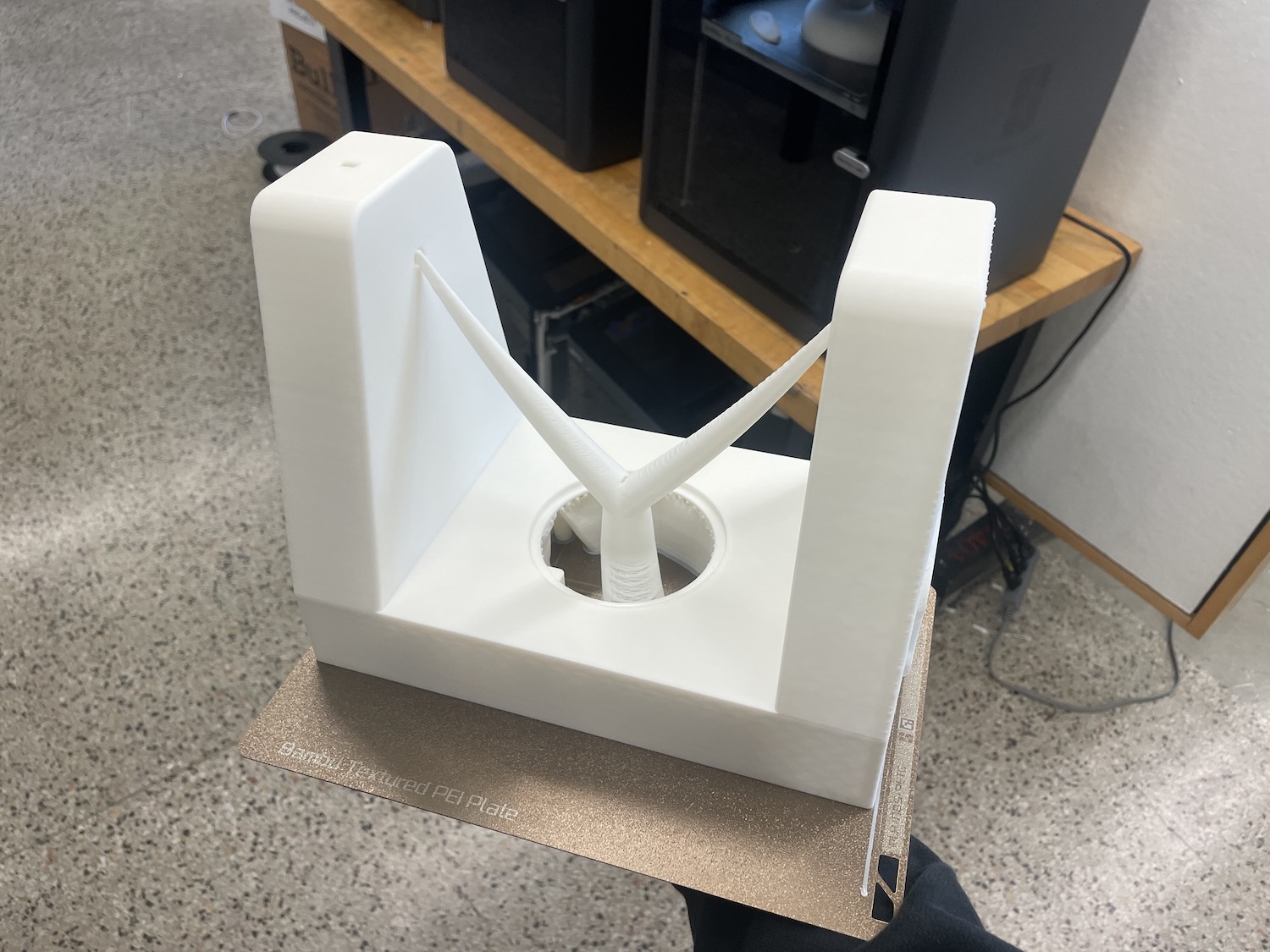
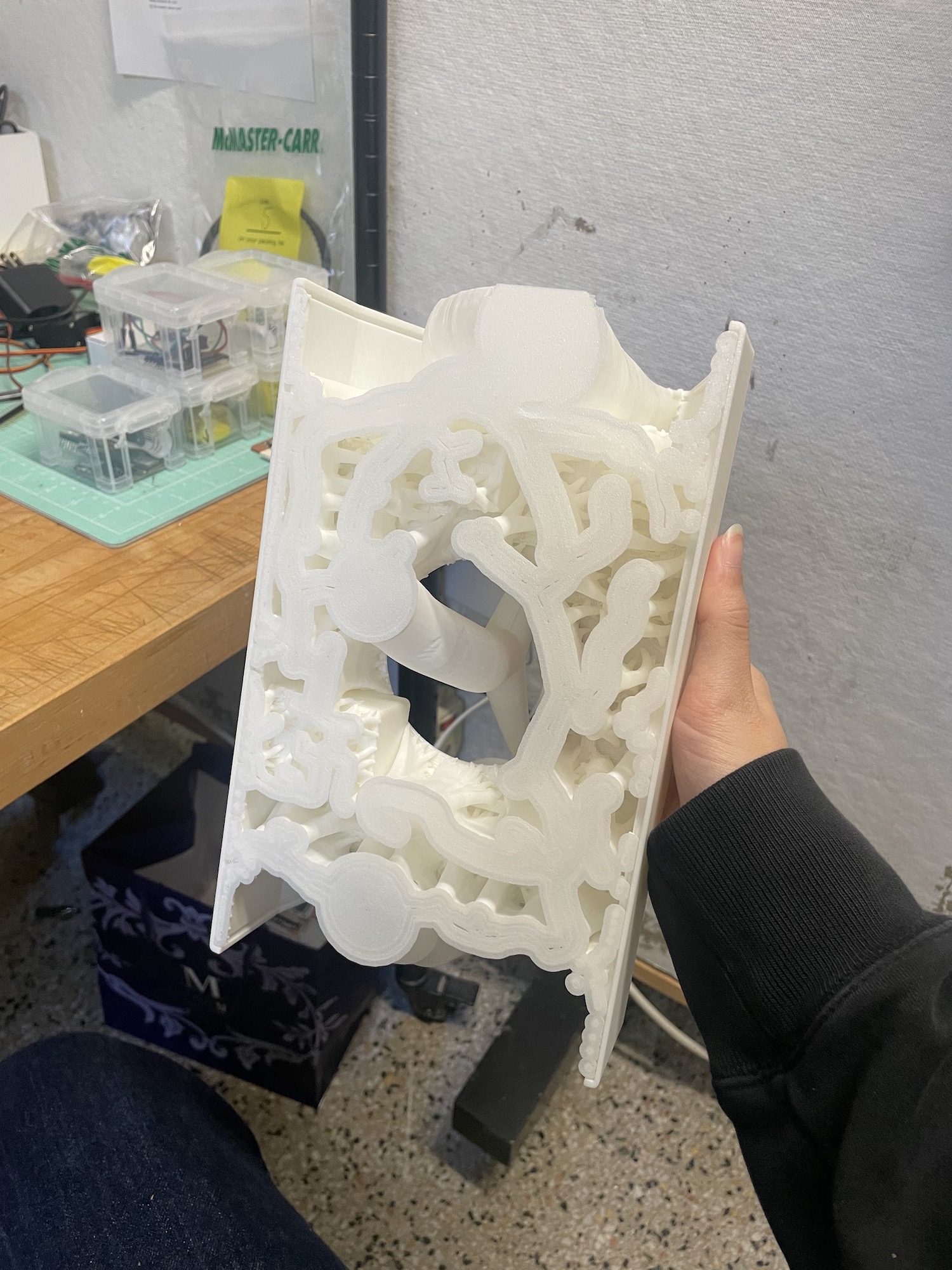
The supports that were generated felt a bit parasitic but cool, so I was sad to tear it all off. This was also a bit of a process.
The other parts were a bit easier to print, all ranging from 2-5 hours on .16 high quality prints. I had to reprint the servo pulley quite a few times in order to get the right size, as well as later reprinting so the screw nests into it.
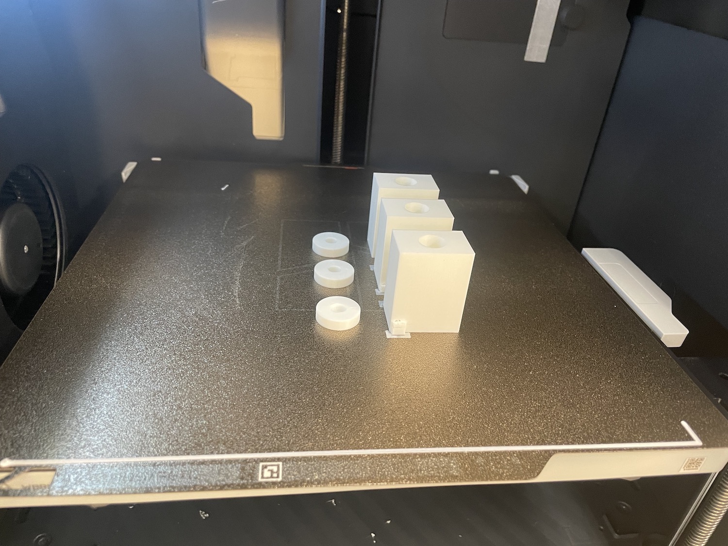
Another part that needed a lot of patience was the top and bottom parts, which needed a bit of sanding in order to slide in. I had to reprint the top as it kept hitting the gears above.
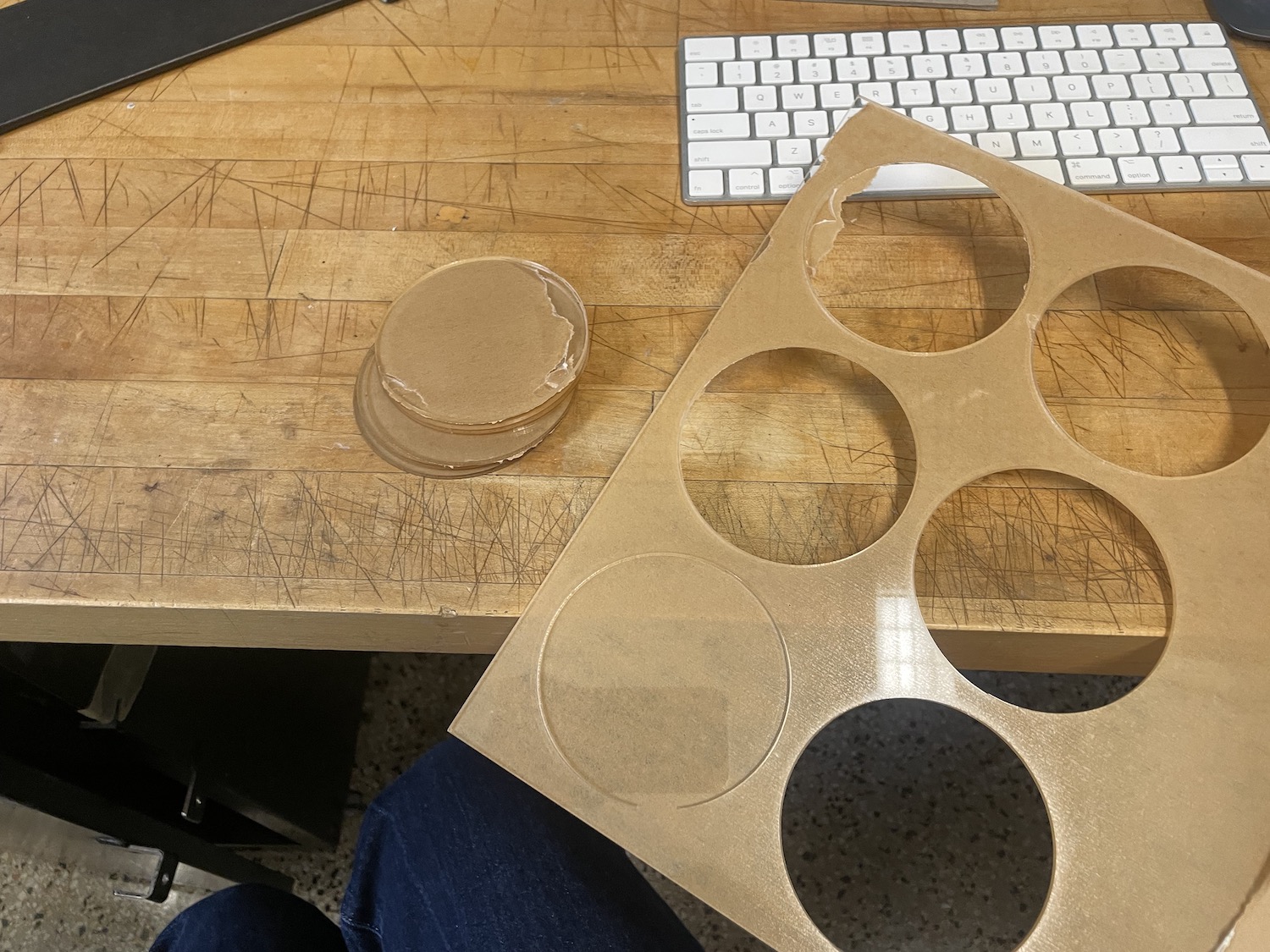
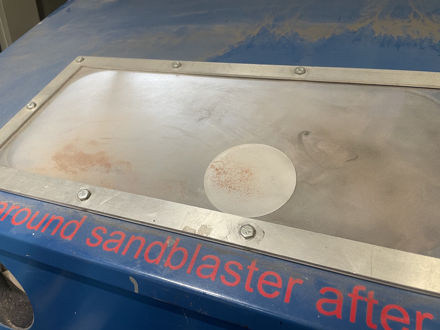
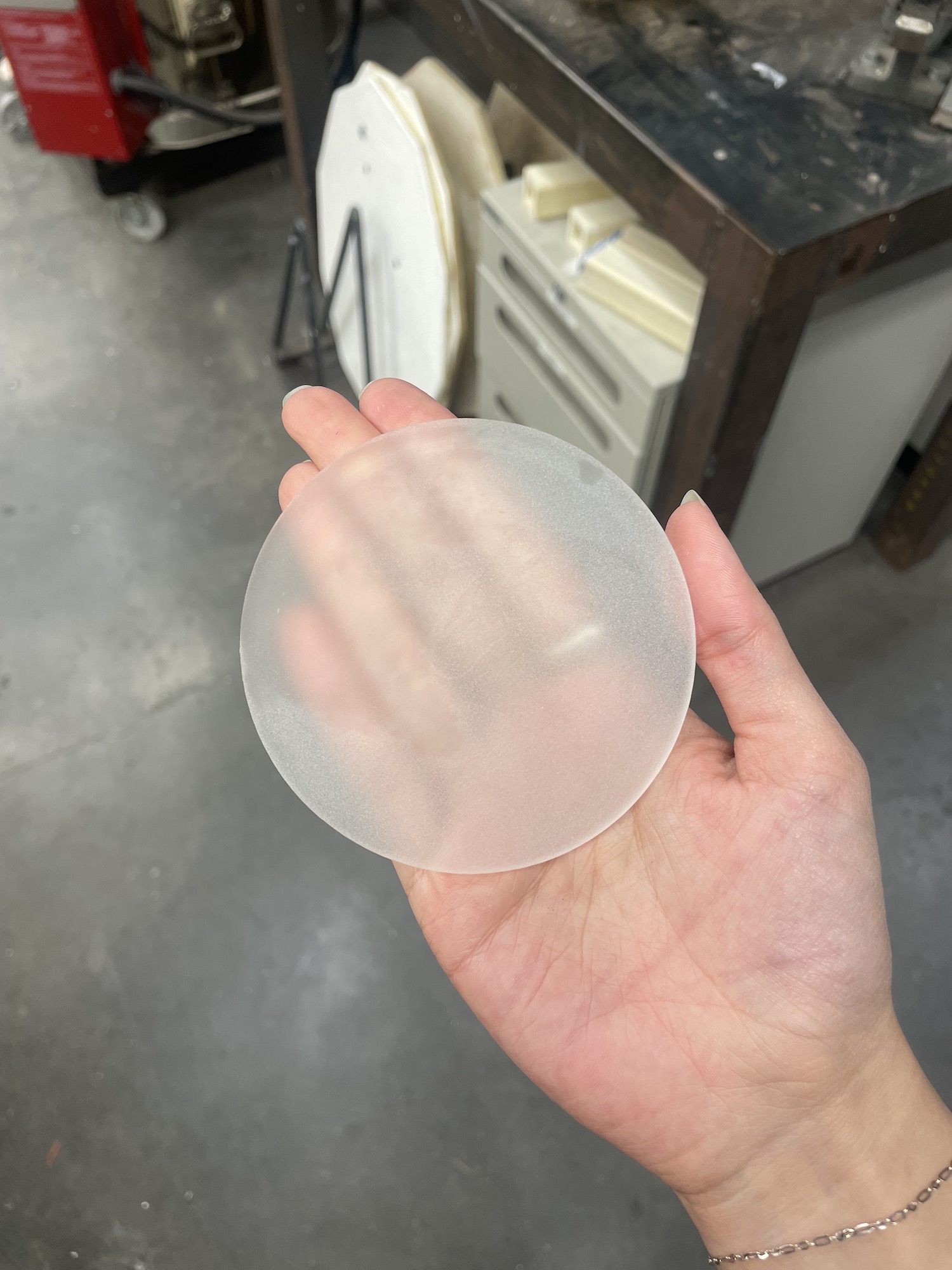
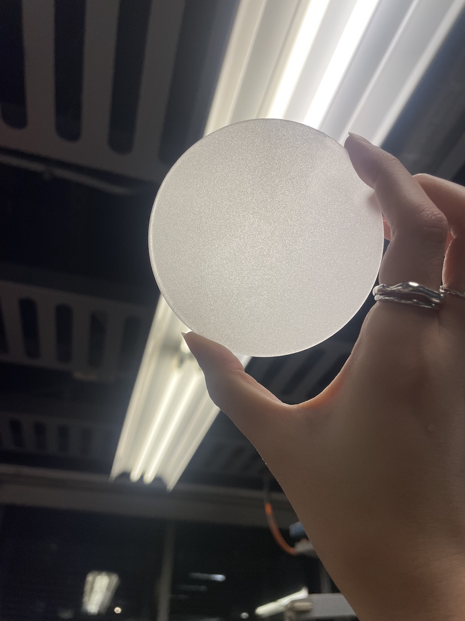
For the window lense, I was orginially going to get a translucent plastic sheet but saw it was quite expensive. Someone had suggested sand basting clear acryilic to get a similar look.
Dan the shop manager at Mars Lab was nice enough to walk through the sandblasting and suggested spray painting the back to help hide the individual pixels from the neopixel.
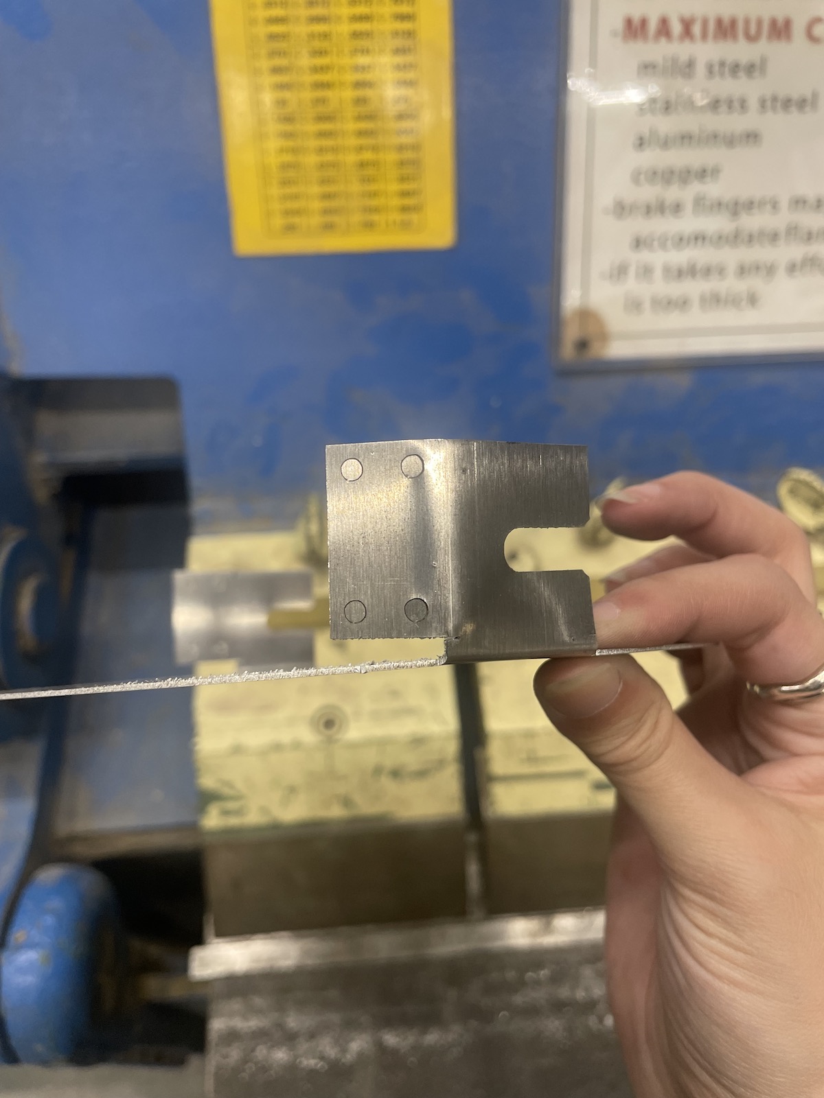
Metal Fin
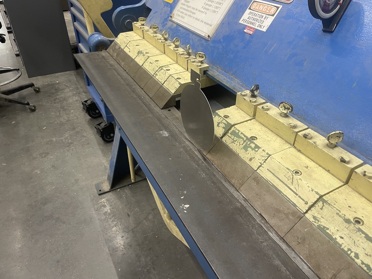
During wildcard week, I cut out the fin using the metal laser cutter (Fablight) along with my wildcard project. I ended up using the stock that was around.
For the design, I needed something that was able to come on and off the rod easily. I created these tabs to screw into some 3D printed parts.
Folding was a bit of a struggle with the first pass so I upped the strength of the raster lines to be able to fold it with just my hands.

Integration/Assembly
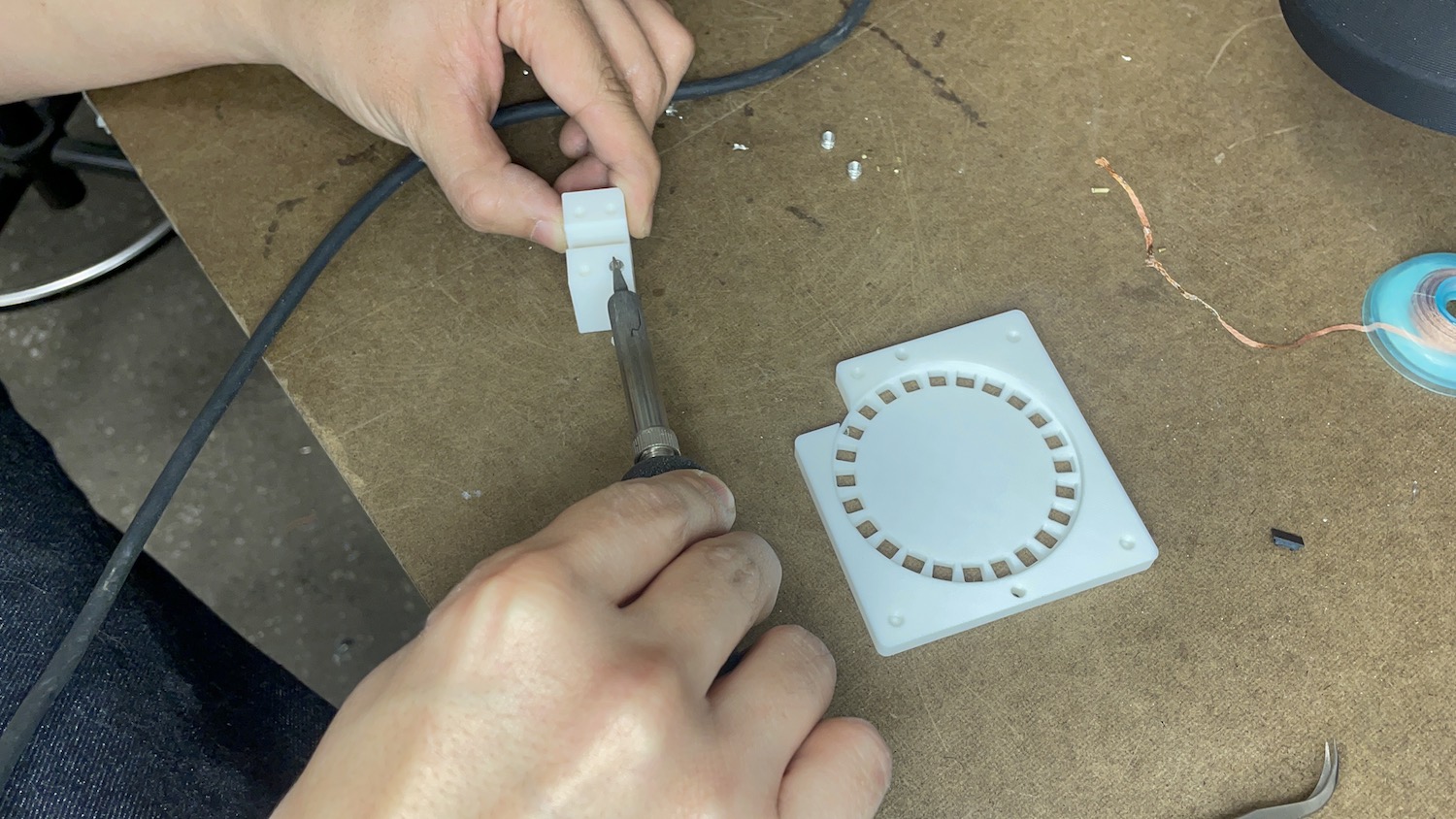
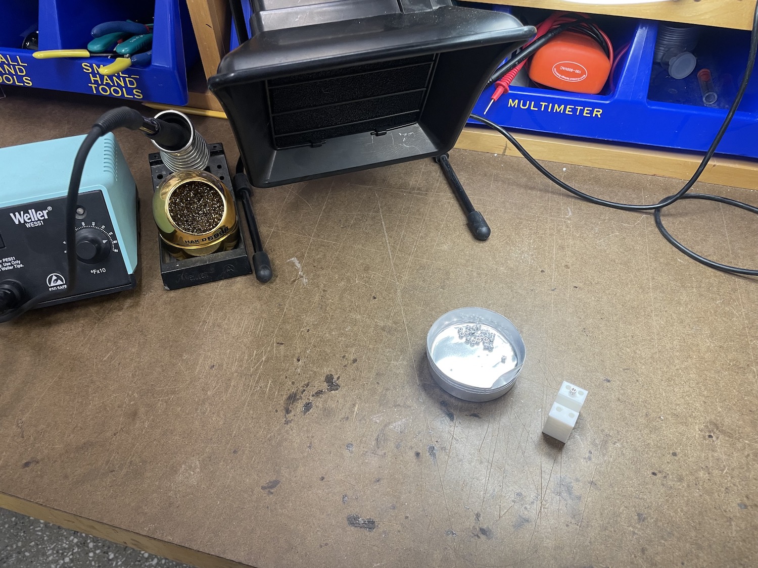
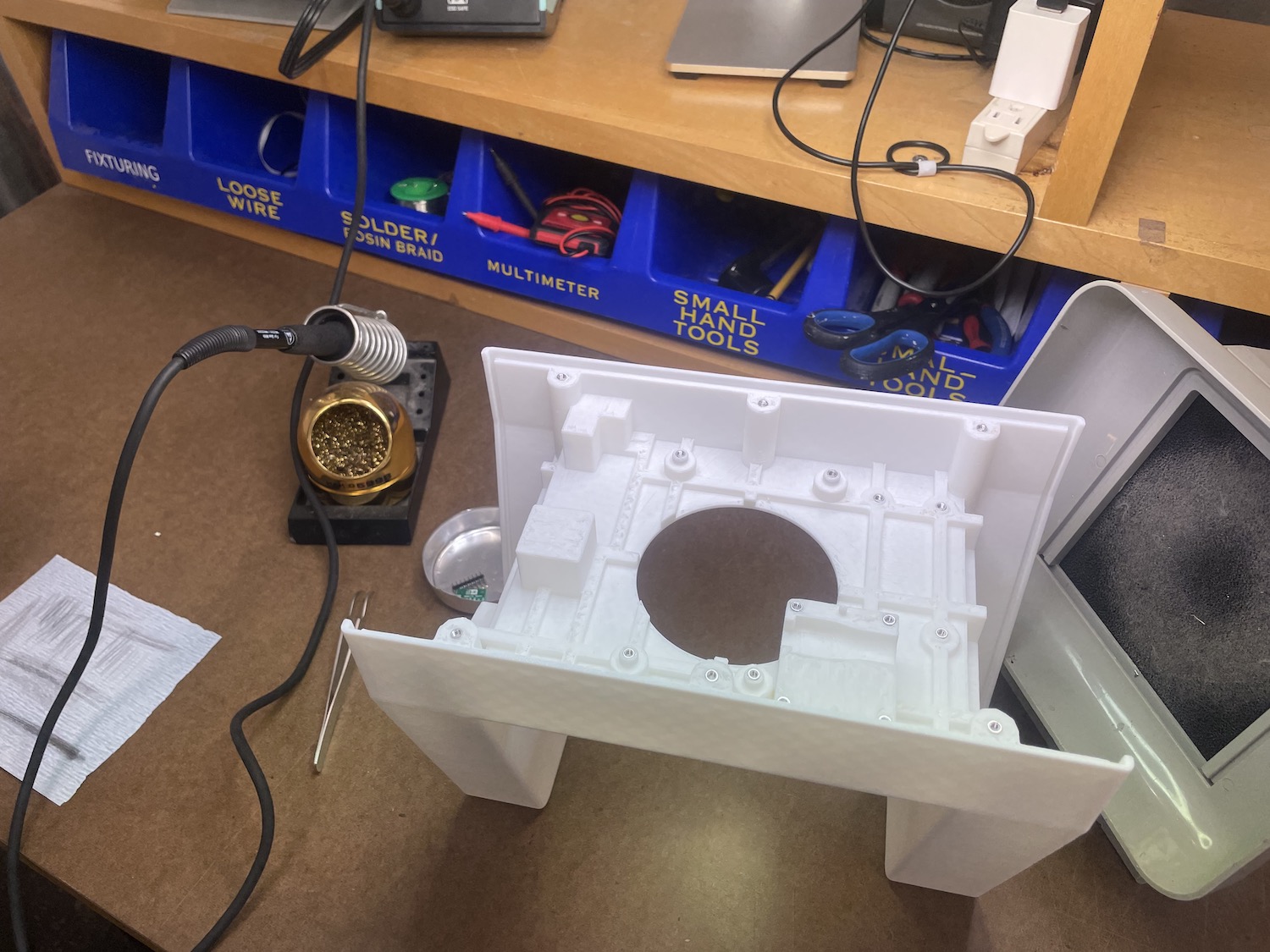
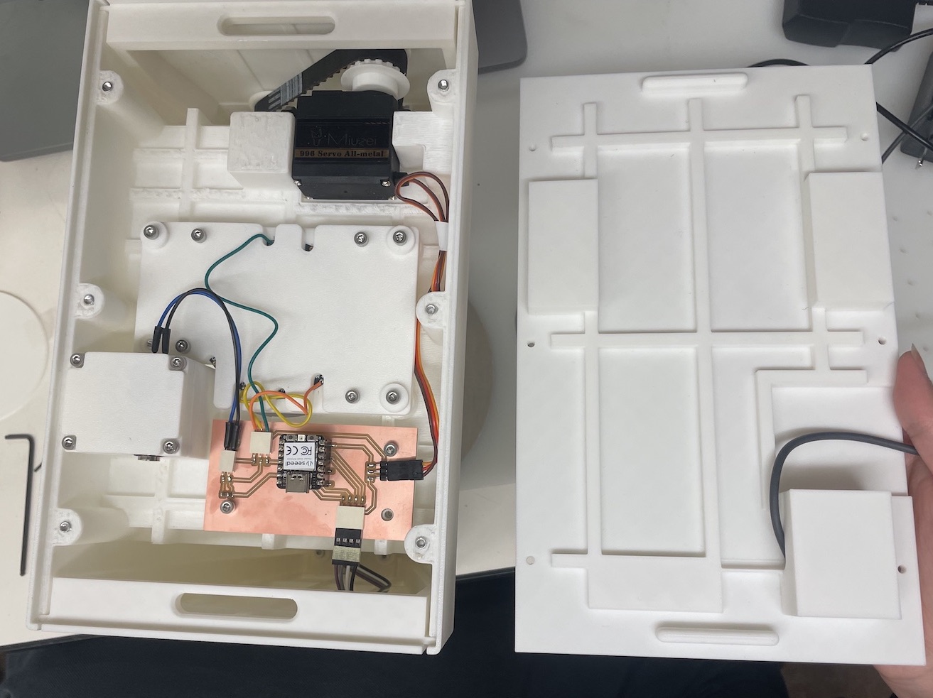
Since a lot of the base was 3D print, I was told to add heat inserts in order to properly screw everything in. I got a tutorial using the archshop's soldering iron
and began my long long journey of melting it into the print. Overall, it took about 1 hour over 40 heat inserts. Surprisingly, every part of the 3D print seemed to fit,
minus the pulley belt, which wasn't able to have any tension. The fix was to reprint the top part have it come around like a triangle.
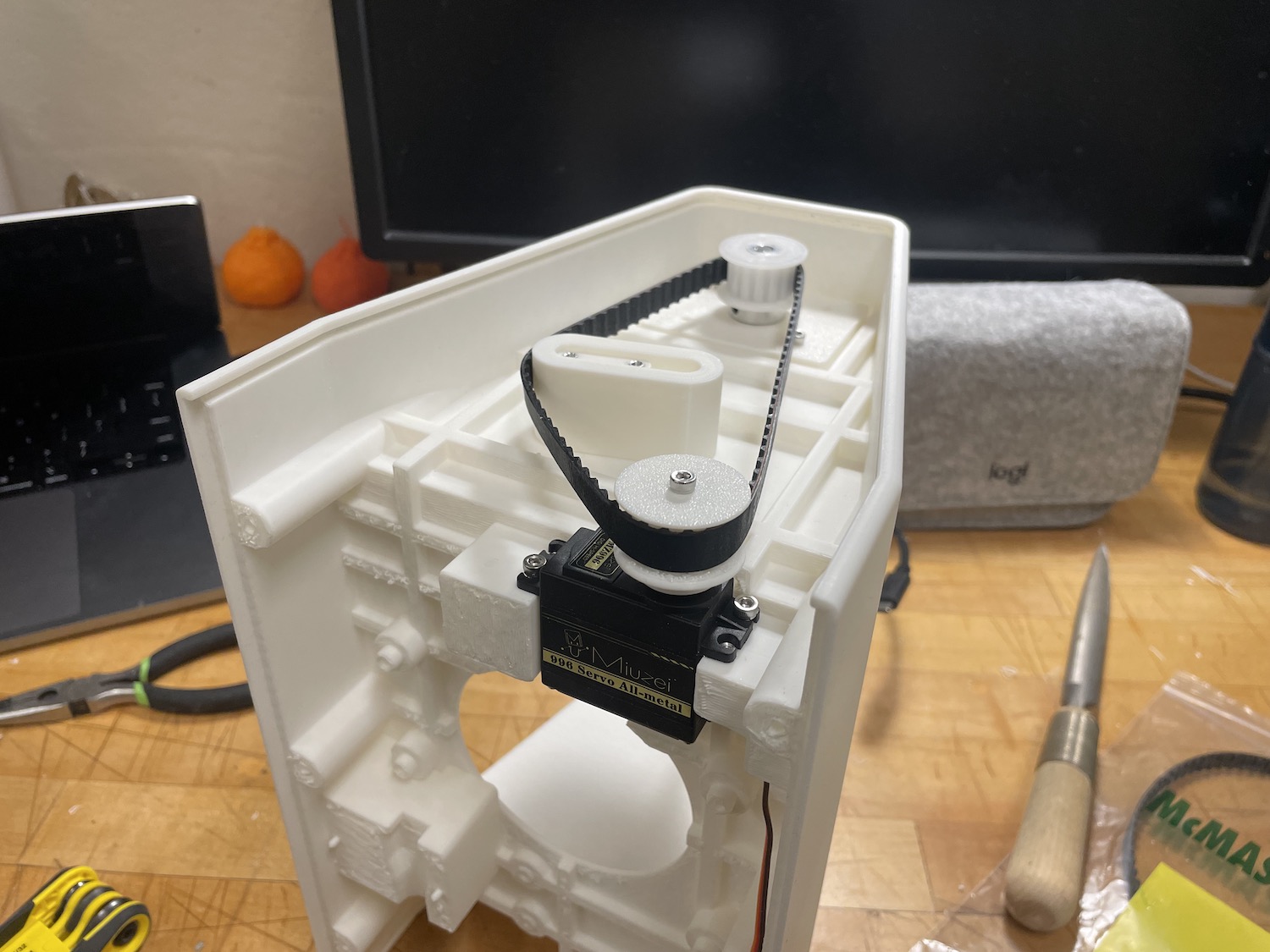
Here is me testing the servo by itself and with the sensor!
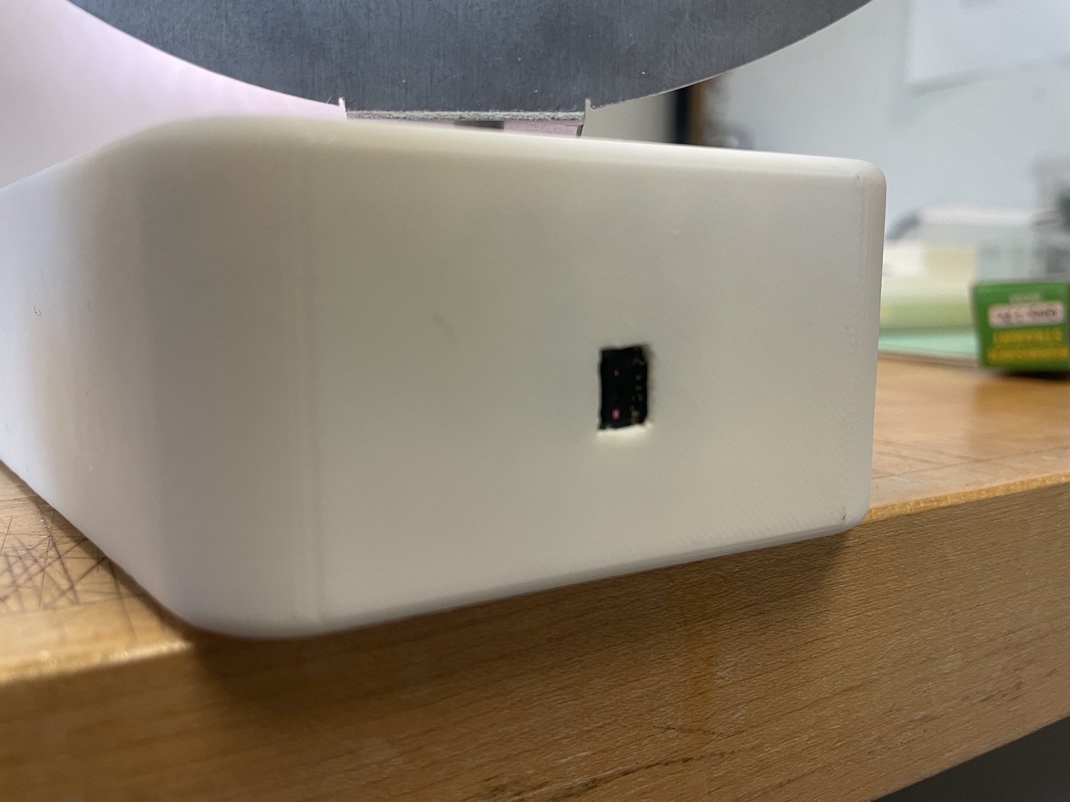
Another problem was that the sensor hole wasn't large enough and the sensor was reading the edges of the opening instead of straight ahead. Anthony suggested taking a dremel to open the hole a bit more.

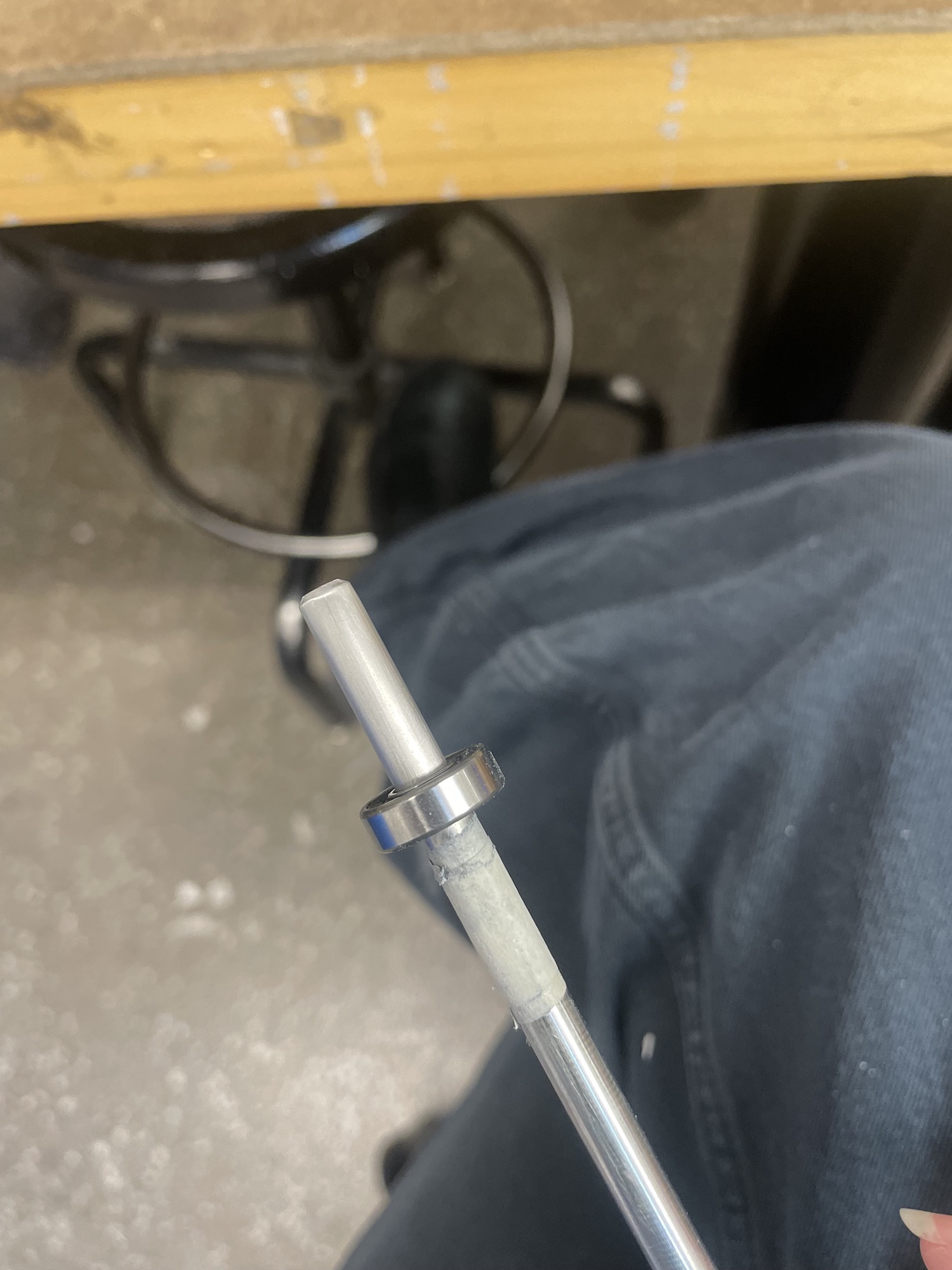
The ball bearing wasn't fitting on the rod without extreme pressure, so I needed to sand down the edges in order to properly fit!
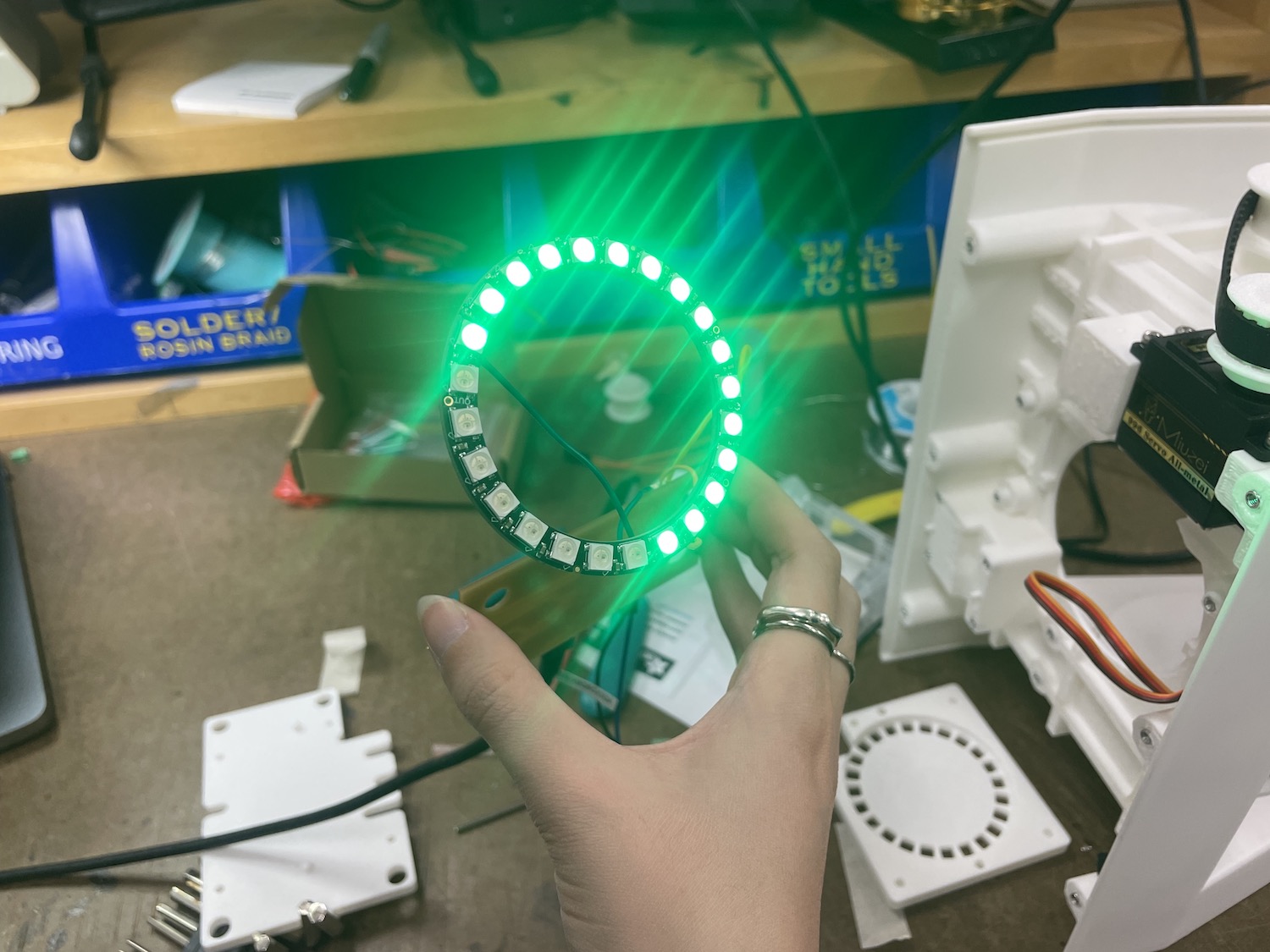
I was scared because my leds got lost in the mail and I had to quickly reorder. As well, you needed to solder directly to the LED so it was one and done situation.
Overall it worked out well and I was able to power it quickly.

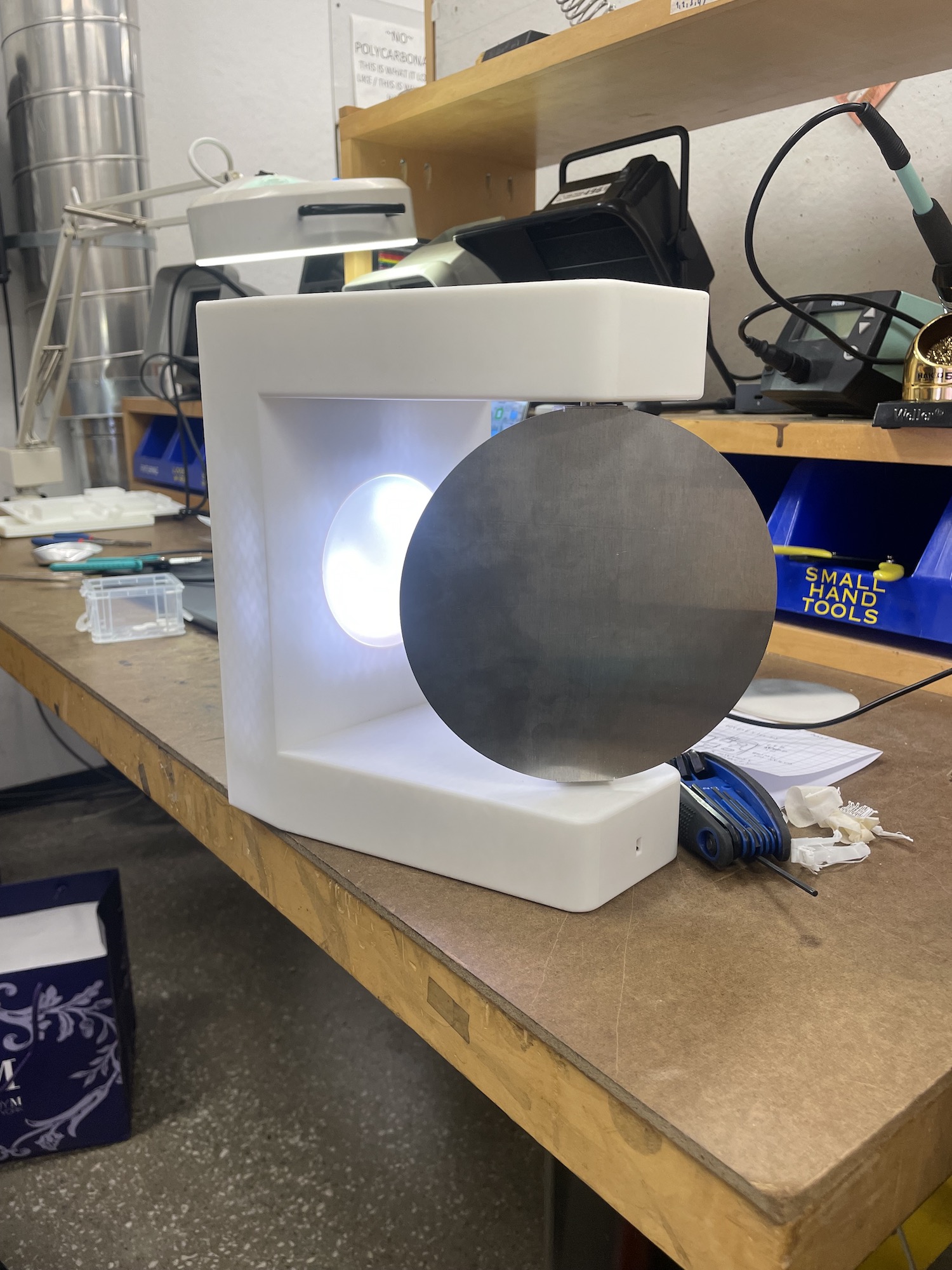
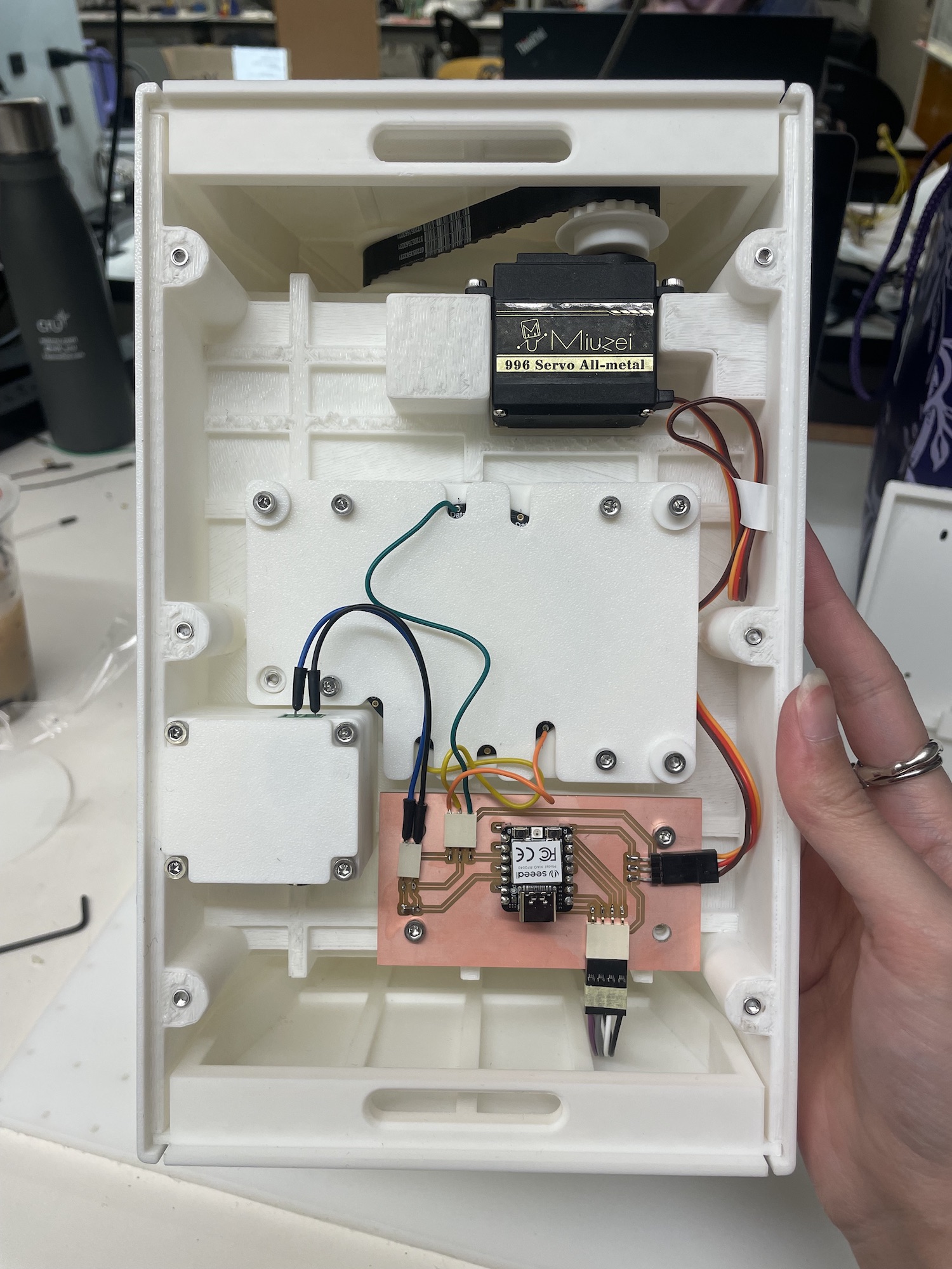
After screwing everything in, here it is! I'm pretty excited that it all turned out well (even though it needs to be covered up..)
Code/Debugging
Once all pieces were assembled, I tested out each invidual component to make sure they all worked. Surprisingly, it did and went smoothly.
This should have been a sign that things were about to go very badly. I went to office hours with Anthony to have the code for the sensor be more accurate.
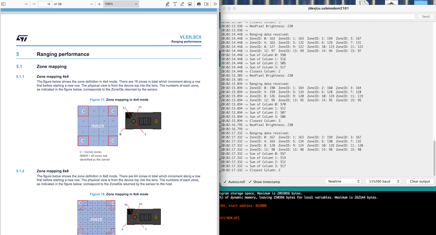
We looked over the datasheet (my bad I should have looked more in depth before), and noted that the sensor would need to be adjusted for the fact I had rotated it in the project.
What was a simple fix, some how took 6 hours. First I needed to take a sum of the columns, and then flip the columns to be rows.
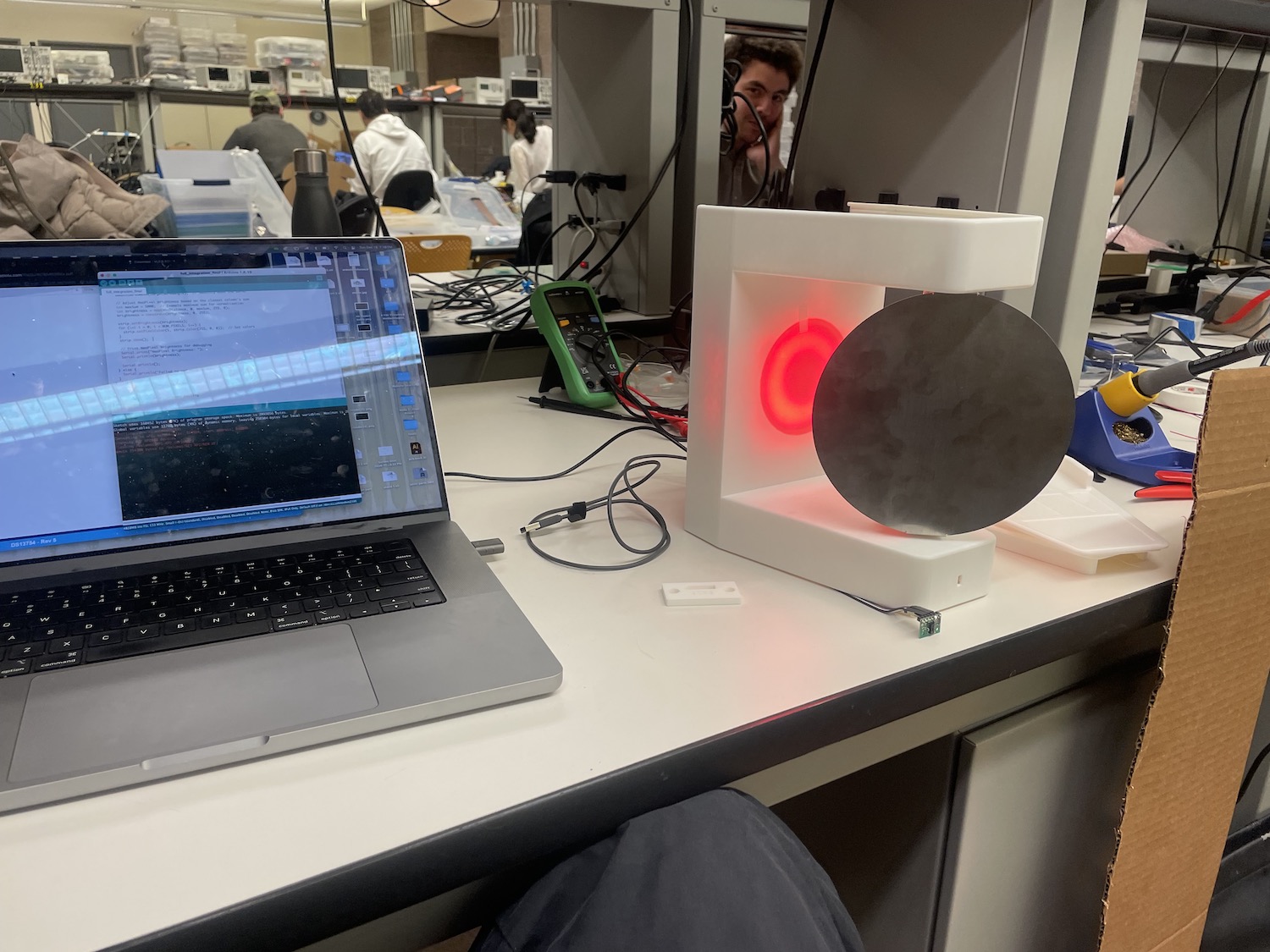
Testing over and over again. The lights were set as red to represent my current mood. Since she was aggressively turning back and forth, she was affectionally coined as an angry robot.
I smoothed out the turning motion, as well as the neopixels dimming and brightening based on location. I do think the light color shifting aren't as noticeable,
but in general it works.
Final code:
    #include
        #include
        #include
        #include

        // sensor and servo setup
        SparkFun_VL53L5CX mySensor;
        VL53L5CX_ResultsData measurementData;
        Servo myServo;

        int servoPin = D6;
        int imageResolution = 0;
        int imageWidth = 0;
        int currentServoAngle = 90;

        // NeoPixel setup
        #define NEOPIXEL_PIN D10
        #define NUM_PIXELS 24
        Adafruit_NeoPixel strip(NUM_PIXELS, NEOPIXEL_PIN, NEO_GRB + NEO_KHZ800);

        //4x4 resolution rows and columns
        const int NUM_ROWS = 4;
        const int NUM_COLS = 4;

        // zone IDs
        int zoneIds[NUM_ROWS][NUM_COLS] = {
          {12, 13, 14, 15},
          {8, 9, 10, 11},
          {4, 5, 6, 7},
          {0, 1, 2, 3}
        };

        // smoothing out servo
        void smoothServoMove(int targetAngle, int stepDelay = 15) {
          if (targetAngle > currentServoAngle) {
            for (int angle = currentServoAngle; angle <= targetAngle; angle++) {
              myServo.write(angle);
              delay(stepDelay);
            }
          } else {
            for (int angle = currentServoAngle; angle >= targetAngle; angle--) {
              myServo.write(angle);
              delay(stepDelay);
            }
          }
          currentServoAngle = targetAngle;  // Update the current angle
        }

        void setup() {
          Serial.begin(115200);
          delay(2000);  // Sensor startup delay

          Wire.begin();
          Wire.setClock(400000);

          Serial.println("Initializing sensor board. This can take up to 10s. Please wait.");

          if (!mySensor.begin()) {
            Serial.println(F("Sensor not found - check your wiring. Freezing."));
            while (1);
          }

          Serial.println("Sensor initialized successfully.");

          mySensor.setResolution(NUM_ROWS * NUM_COLS);
          imageResolution = mySensor.getResolution();
          imageWidth = sqrt(imageResolution);

          myServo.attach(servoPin);
          myServo.write(currentServoAngle);

          // start up NeoPixel
          strip.begin();
          strip.show();
          strip.setBrightness(0);

          delay(5000);  // Delay before starting ranging
          mySensor.startRanging();
        }

        void loop() {
          if (mySensor.isDataReady()) {
            if (mySensor.getRangingData(&measurementData)) {
              Serial.println("Ranging data received:");

              // array sum of distances for each column
              int sumPerColumn[NUM_COLS] = {0};
              int minDistance = 99999;
              int closestColumn = -1;

              // sensor data in a 4x4 grid
              for (int row = 0; row < NUM_ROWS; row++) {
                for (int col = 0; col < NUM_COLS; col++) {
                  int flippedCol = NUM_COLS - 1 - col;
                  int index = row * NUM_COLS + flippedCol;
                  int distance = measurementData.distance_mm[index];

                  // debugging
                  Serial.print("Zone ");
                  Serial.print(zoneIds[row][col]);
                  Serial.print(": ");
                  Serial.print(distance);
                  Serial.print("\t");

                  int columnGroup = zoneIds[row][col] / 4;

                  sumPerColumn[columnGroup] += distance;
                }
                Serial.println();  // Newline at the end of each row
              }

              // closest column
              for (int col = 0; col < NUM_COLS; col++) {
                if (sumPerColumn[col] < minDistance) {
                  minDistance = sumPerColumn[col];
                  closestColumn = col;
                }

                Serial.print("Sum of Column ");
                Serial.print(col);
                Serial.print(": ");
                Serial.println(sumPerColumn[col]);
              }

              // debugging
              Serial.print("Closest Column: ");
              Serial.println(closestColumn);

              // map closest column to a servo angle
              int targetServoAngle = map(closestColumn, 0, NUM_COLS - 1, 0, 180);
              smoothServoMove(targetServoAngle);  // Smoothly move the servo

              // NeoPixel brightness
              int maxSum = 5000;  // Example maximum sum for normalization
              int brightness = map(minDistance, 0, maxSum, 255, 50);
              brightness = constrain(brightness, 50, 255);

              strip.setBrightness(brightness);
              for (int i = 0; i < NUM_PIXELS; i++) {
                strip.setPixelColor(i, strip.Color(255, 180, 100));
              }
              strip.show();

              //debugging
              Serial.print("NeoPixel Brightness: ");
              Serial.println(brightness);

              Serial.println();
            } else {
              Serial.println("Failed to get ranging data.");
            }
          } else {
            Serial.println("Sensor data not ready yet.");
          }

          delay(500);
        }
Final Thoughts
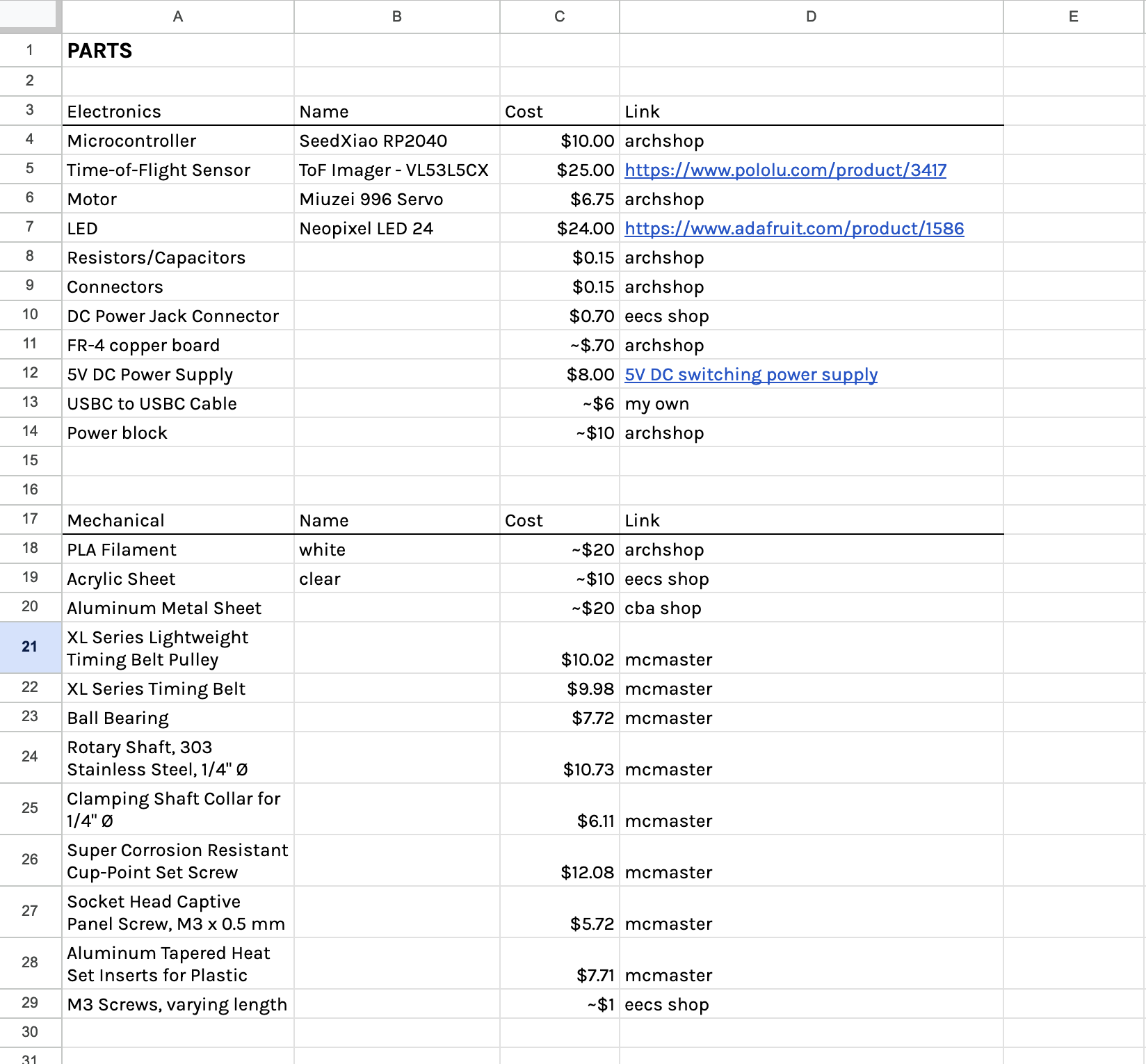
Cost of Materials
Summary & Reflections
I created a responsive nightlight that tracks movement using a VL53L5CX sensor, a Miuzei 996 servo, and a Xiao RP2040 on a custom PCB. The sensor detects motion and location data, allowing the servo to adjust the fins direction, providing diffuse light to set the path. I sandblasted acrylic for a softer glow and refined the design through troubleshooting fit, stability, and servo responsiveness. The process was an exercise in balancing digital design and physical prototyping, forcing me to iterate quickly and readjust when things didn't fit perfectly. I felt like I gained a deeper understanding of movement-based interactivity and the nuances of translating conceptual ideas into functional, responsive designs using a variety of different digital fabrication tools. Each iteration brought me closer to a nightlight that’s dynamic yet thoughtfully crafted. A big shout out to the Architecture group, Anthony, Diana, the rest of the TAs and Neil for a great class!