Week 08 — Input Devices
PCB Design Part One
This week, we shifted back into electronics design. Taking another step towards my final, I wanted to add a sensor to track the distance of an object.
As well, seeing as the following week would be Outputs, I wanted to save some time and see if I could put both components into one board.
I first looked into the VL53L5CX Time-of-Flight 8x8 multizone ranging sensors, and soon realized I would be in a world of hurt.
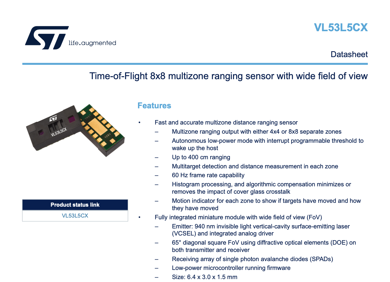
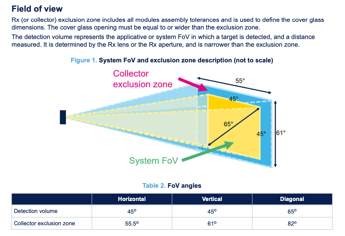
The tiny chip was both going to be a pain to solder and had many components in order for it to work.
I took a look at the datasheet and began adding all the components onto KiCad. I sent this version to Anthony for review and got some helpful feedback.
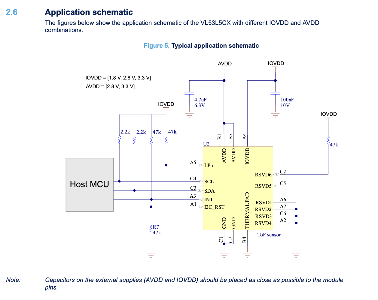
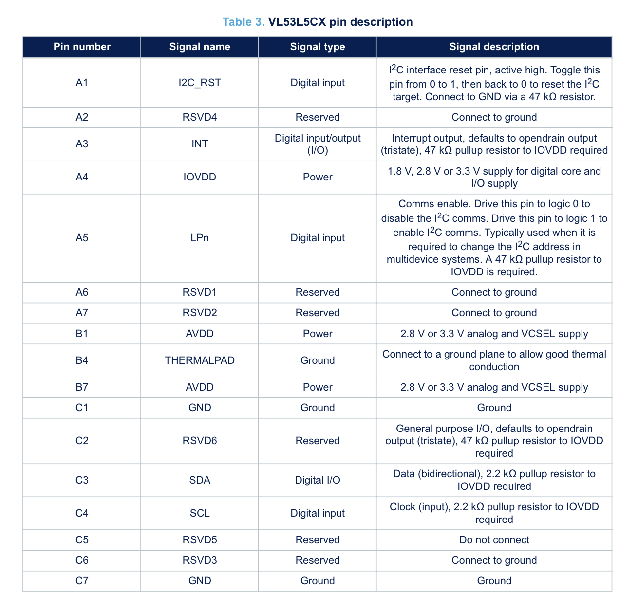
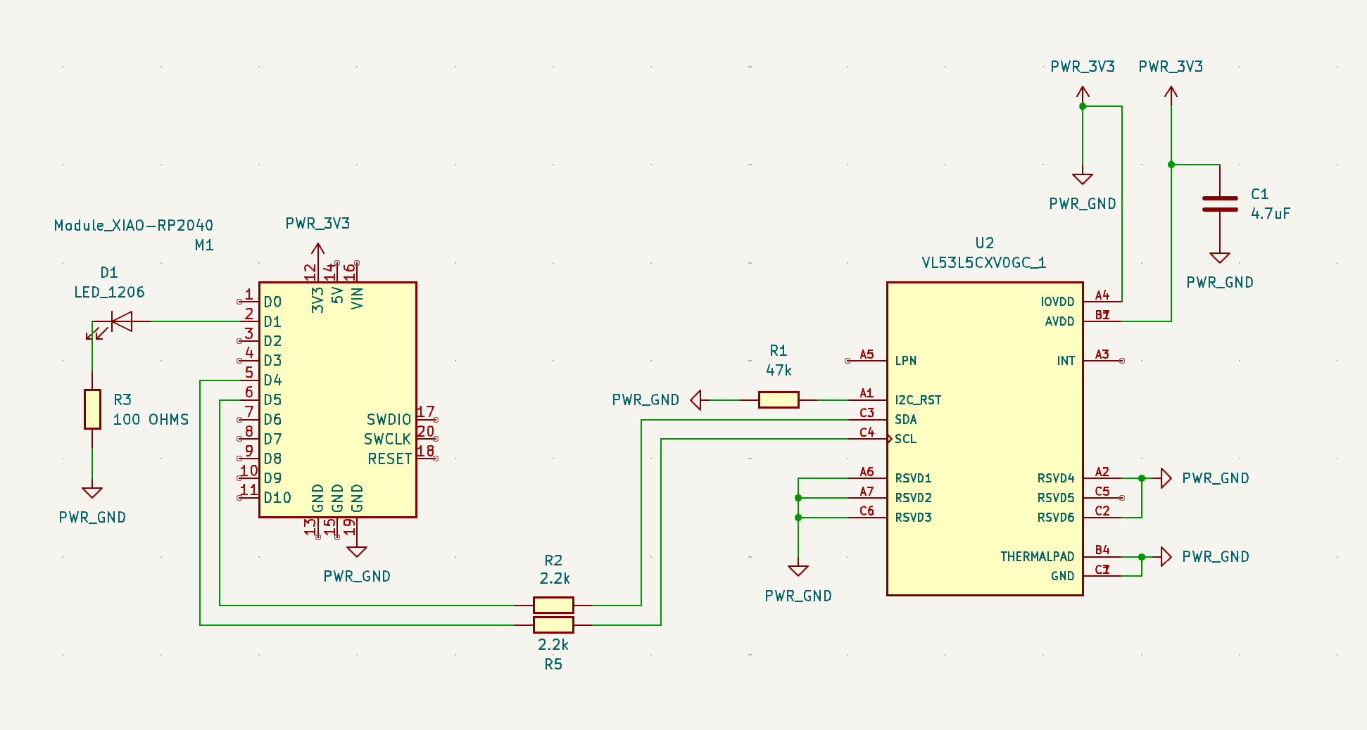
He mentioned some of the pathways weren't probably connected so I took a look at the datasheet again to update everything.
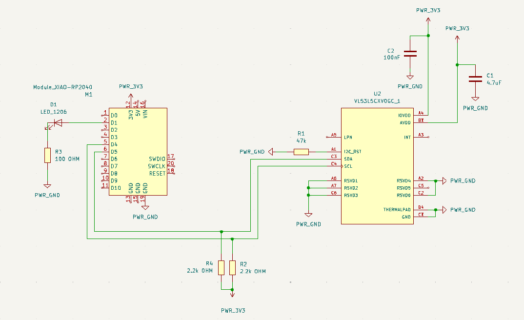
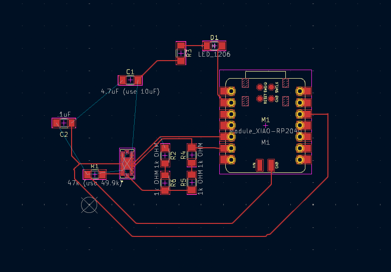
It was at this point I was struggling transitioning the schematic to the PCB design.
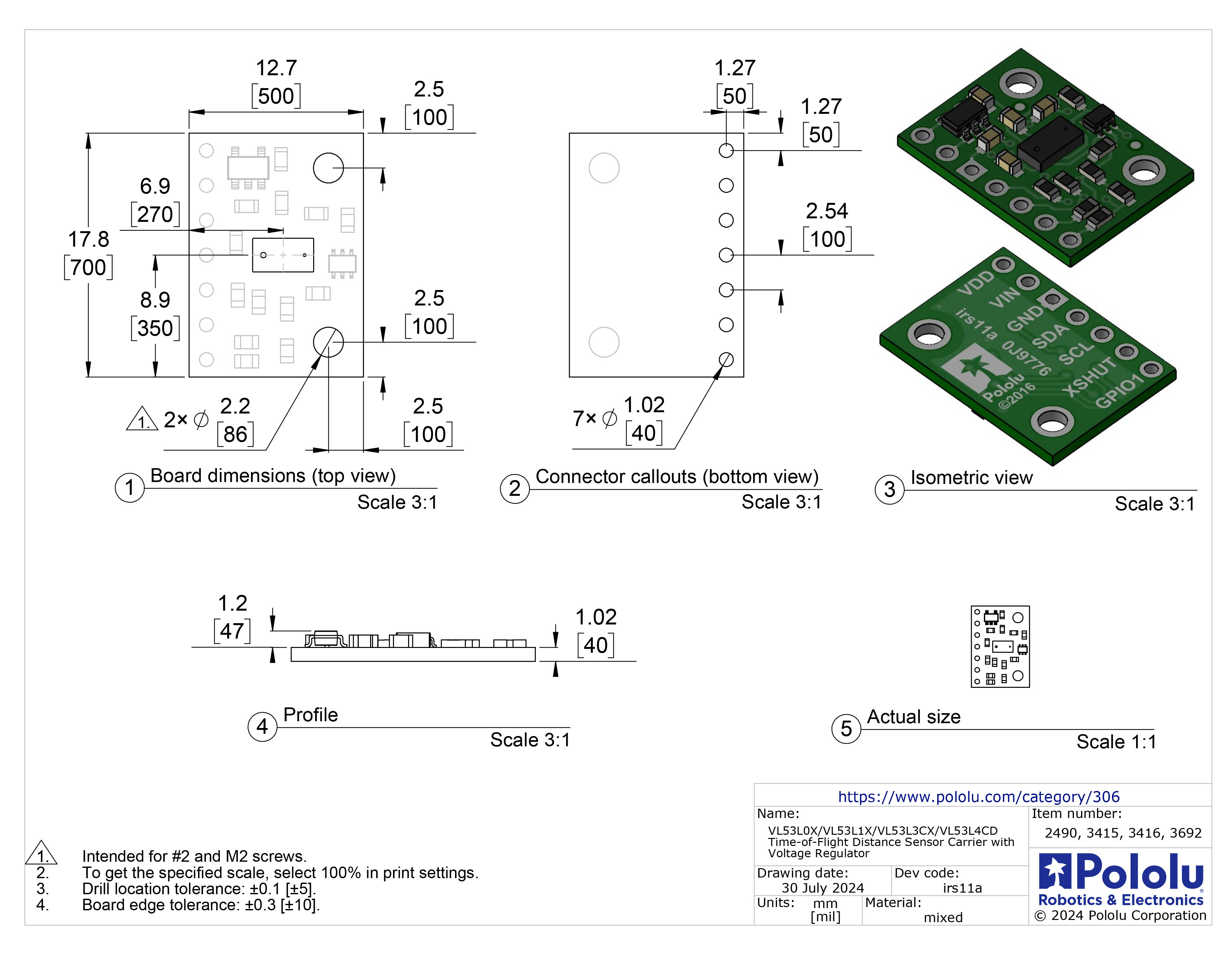
As I was attempting to create the pathways, my classmate Gert pointed out I could just use a breakout board that all the components I needed....
The sensor was a less complex model, but for what I wanted to do, it would work.
PCB Design Part Two
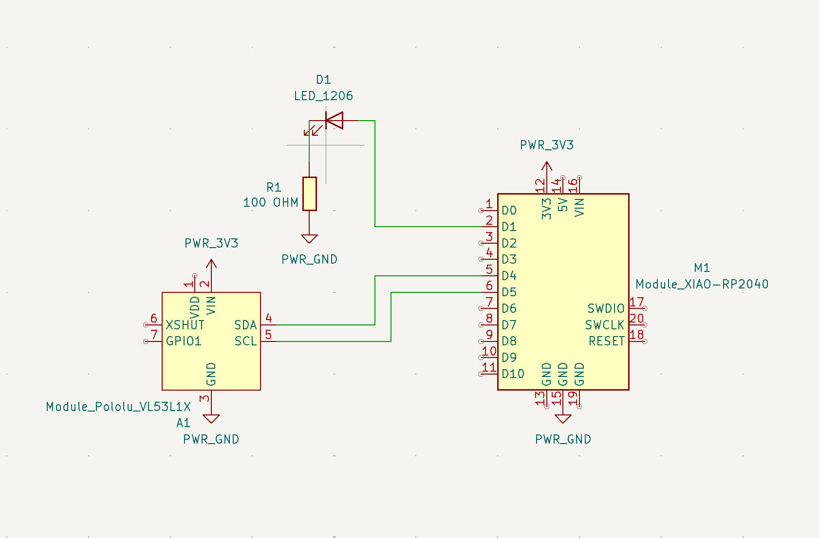
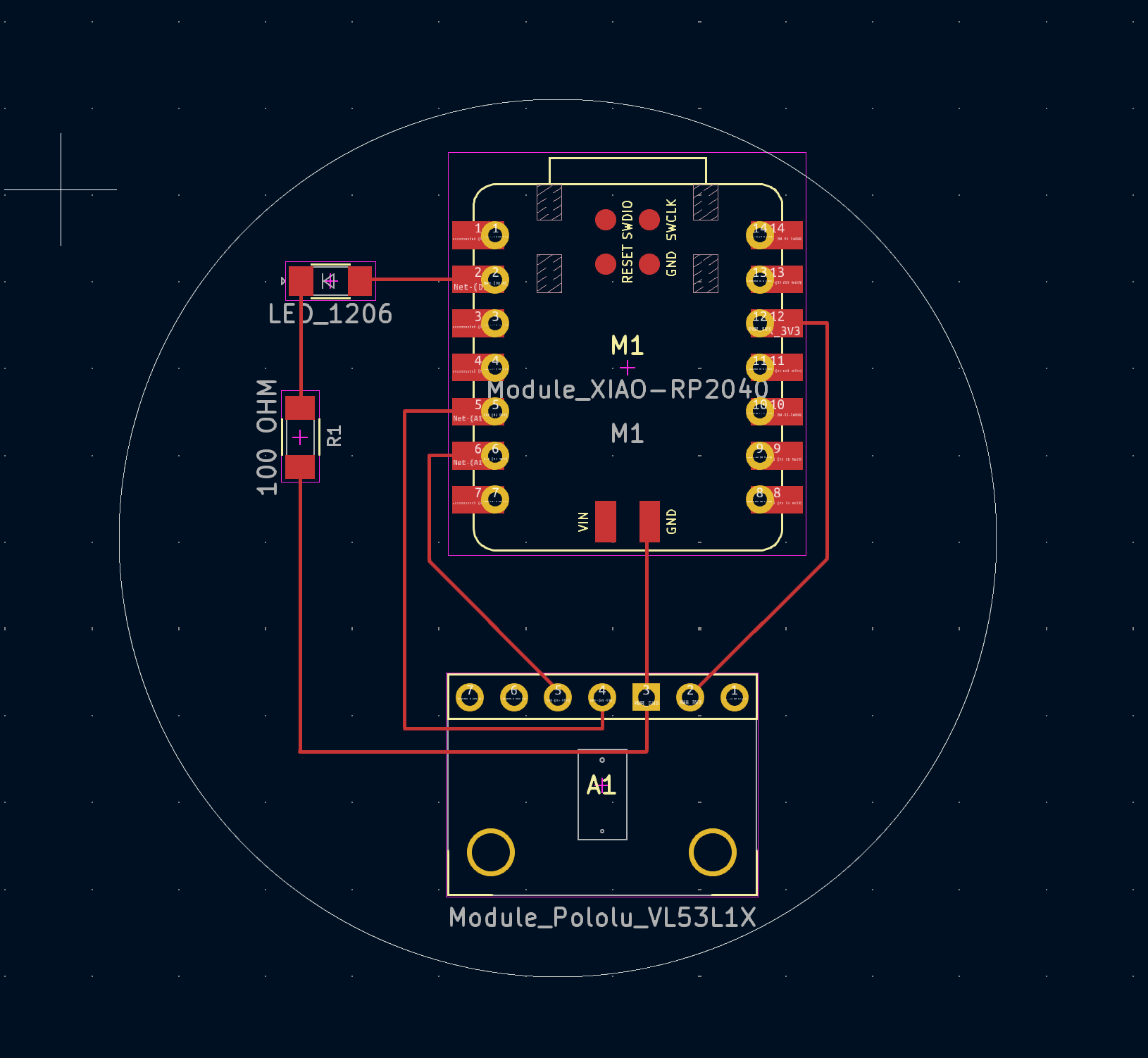
Looking at the new datasheet, the schematic was a lot easier to produce and I was able to great my PCB board rather quickly.
I guess everything before wasn't a waste to learn...
I explored the files to gerber and headed to the shop.
Milling & Soldering the Board
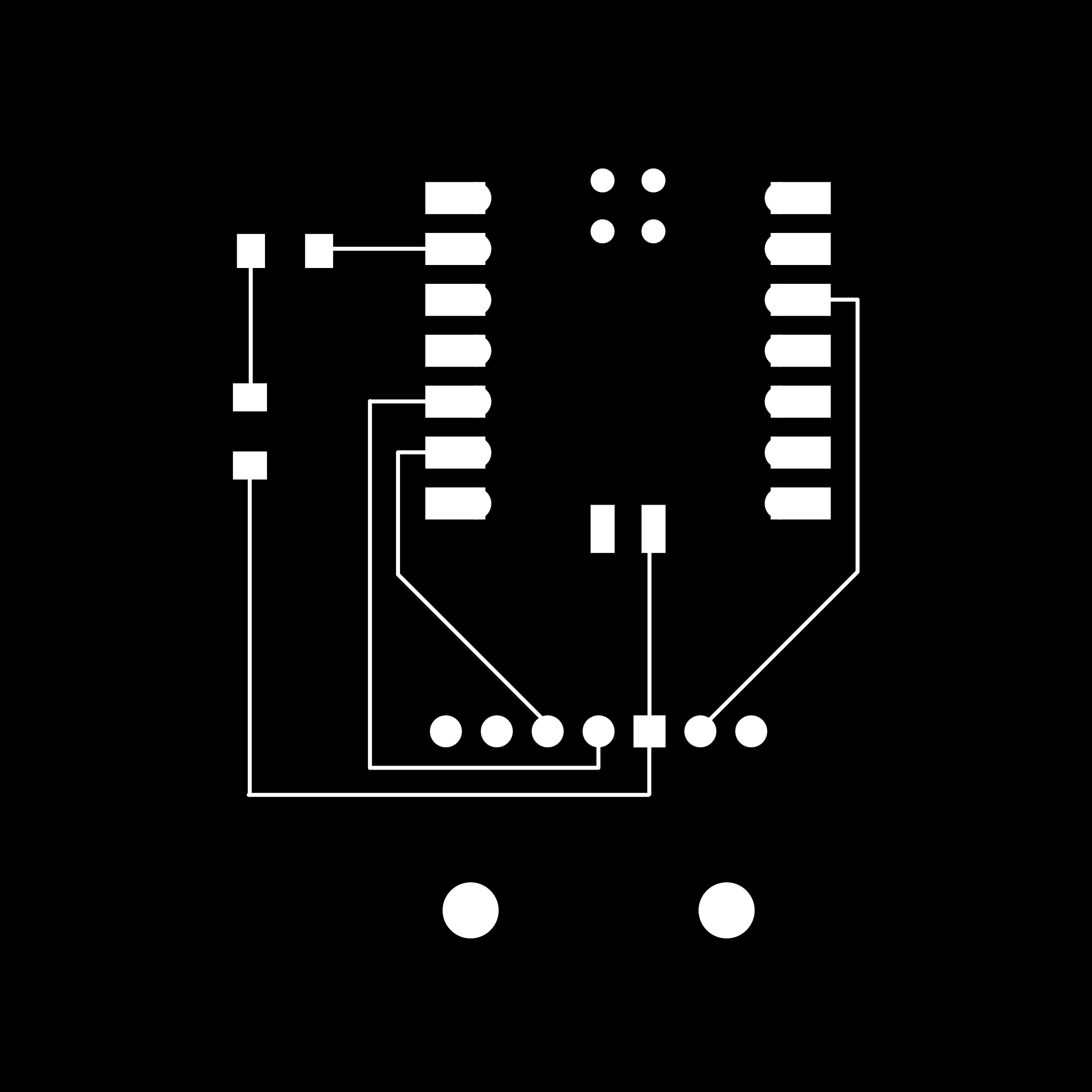
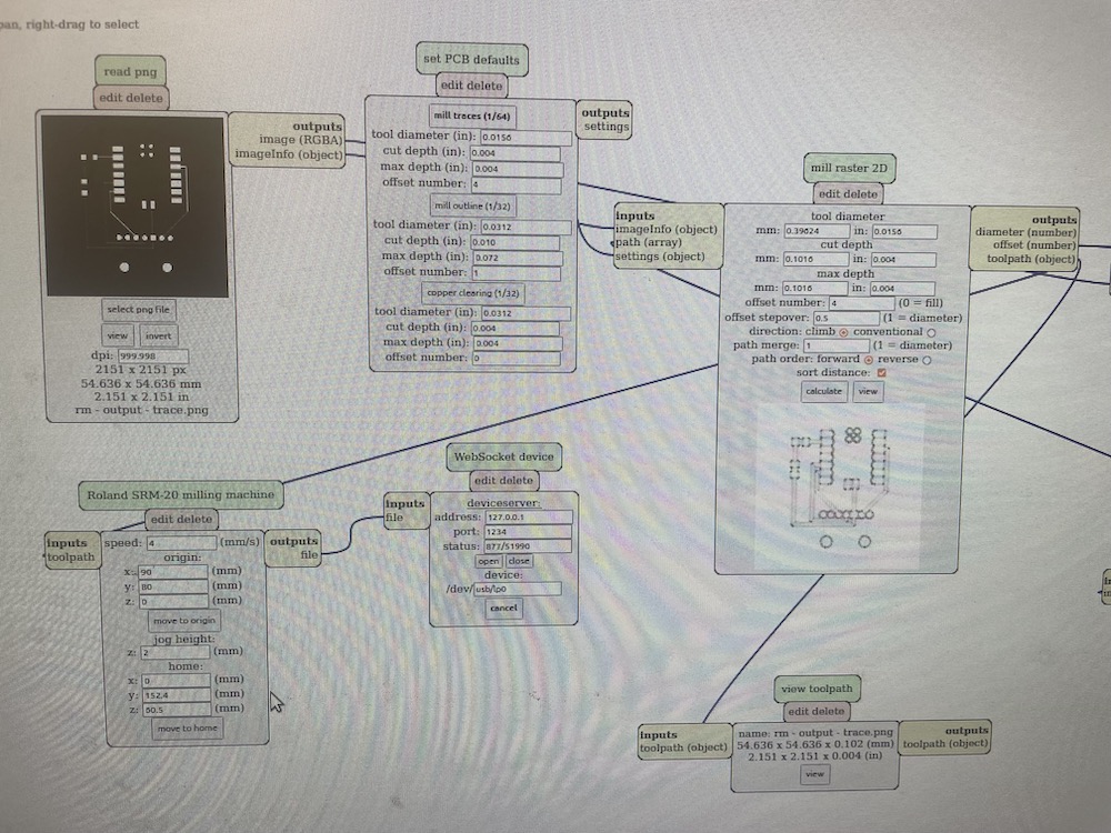
Formatting my board using GerberToImgsoftware, I converted the outline first, lock the origin and dimensions, and then converted the trace file.
In the second milling training session, I learned to not set the X and Y axis in the same spot as everyone else, so I shifted everything over.
My first board wasn't probably secured and came up halfway through the training. The second time I swapped to a smaller board size and more tape.
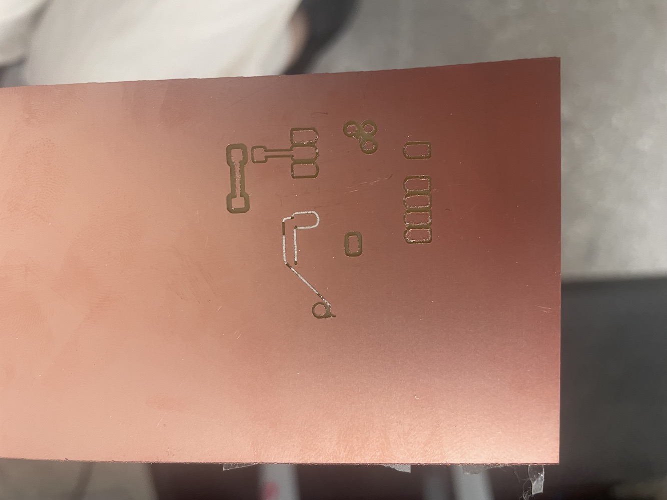
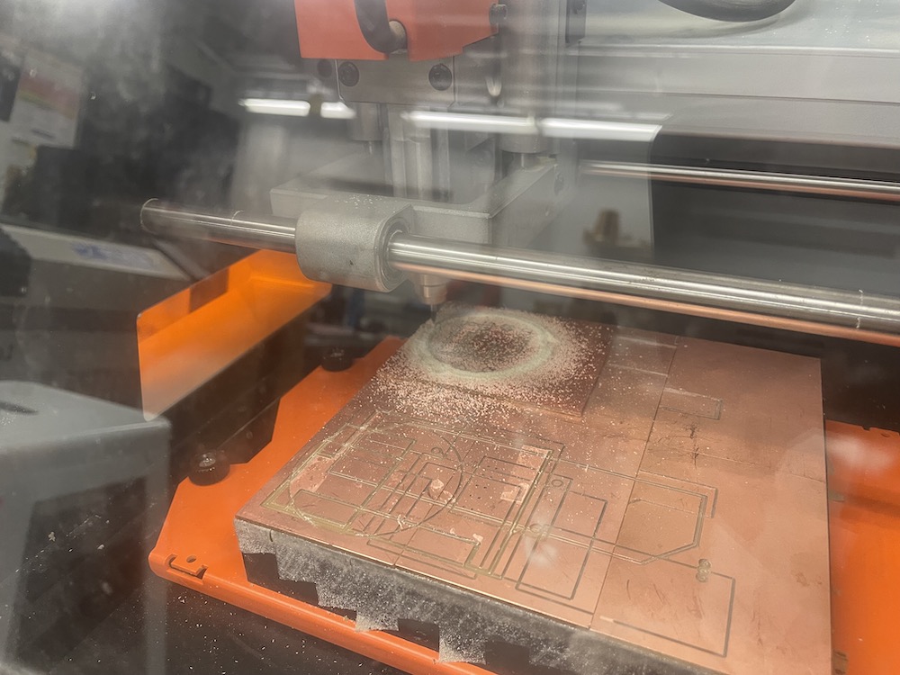
Soldering this time round was easier then before, as I had gotten the hang of it.
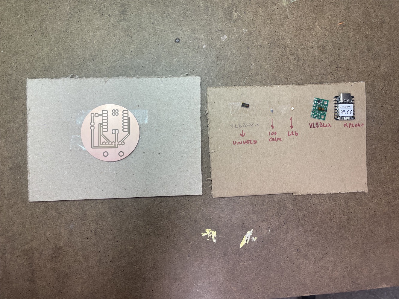
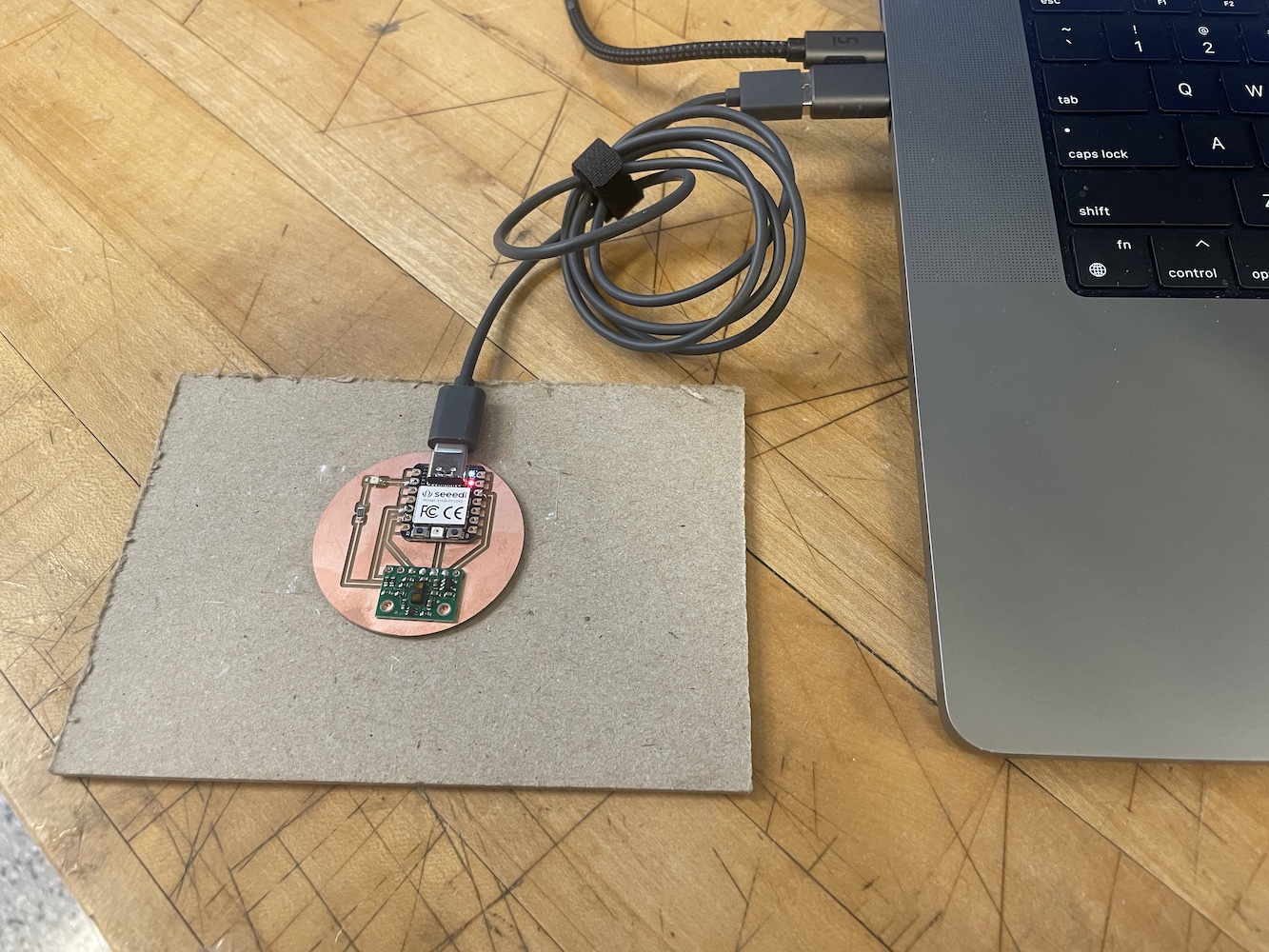
Coding & Debugging the Board
I really struggled with coding the board this time around. Using the same Micropython set up, I updated the board software to RP2040. Of course, the first time around nothing was working.
The first step I took was to make sure there wasn't an issue with the chip and was able to turn on the board's lights easily.
The second step was using the multimeter to make sure everything was connected. It was to my knowledge, but I am also not yet knowledgeable on using it.
The third step was adding the VL53L1X library to the microprocessor. I followed these steps from chatGPT; the adafruit one didn't work but I managed to find another one specifically for the Seed Xiao RP2040 and Micropython.
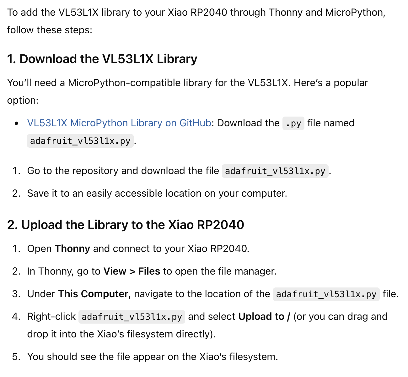
The four step (with the help of chatGPT) was to see if the device could be read at all. It seemed to work but still the original code wasn't working.
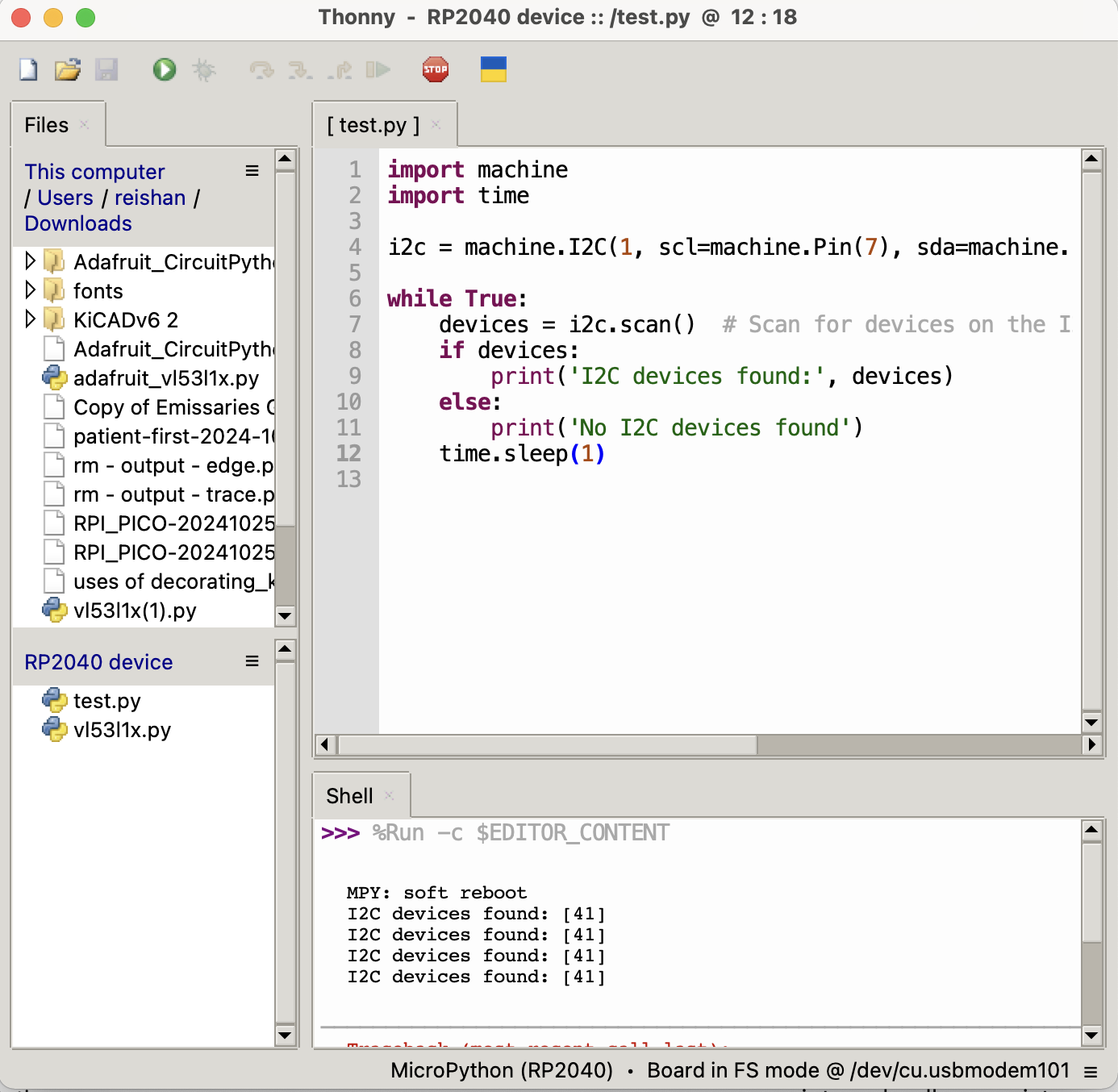
The fifth step was to see if the basic I2C communication was functional using the code below. I got the error [Errno 5] EIO which means a communication error of some sort...
I double checked the voltage of 3.3v and its compatibility, so my next step is to use external pull-up resistors (which I forgot to add the first time around...)
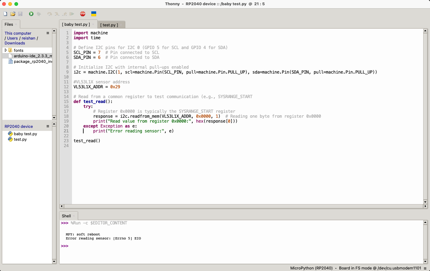
At this point, I ran out of time to run to Anthnoy for help, so stay tuned.
One Week Later
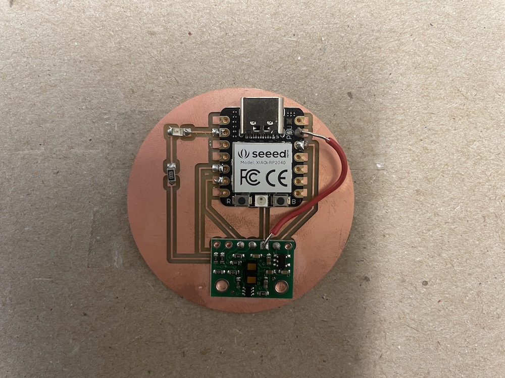
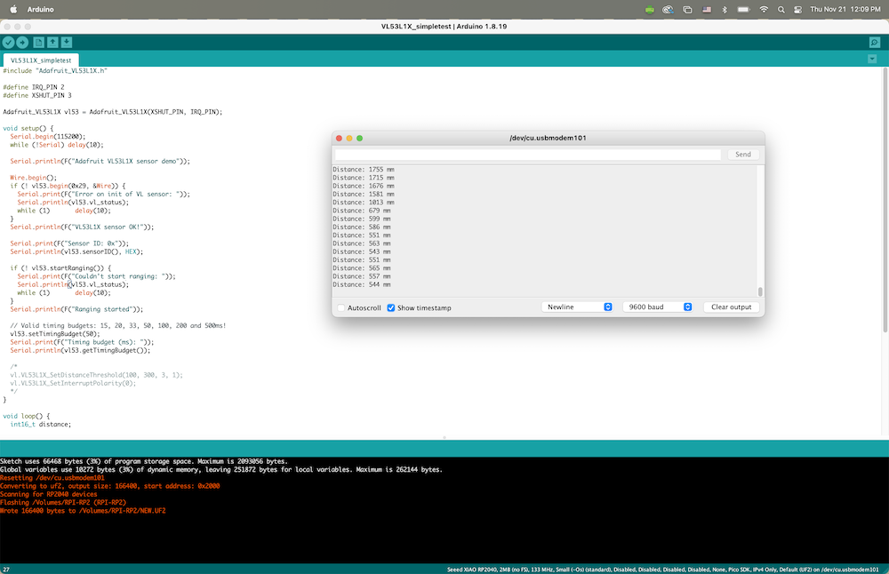
I finally met with Anthony and he pointed out that since I was trying to connect to a ground underneath the microcontroller, it may not be probably secured. We ended up soldering a cable from the ground point on my sensor to the microcontroller, and it worked! We swapped over to Arduino (not the Arduino IDE but the older version of Arduino), as the newest version wasn't probably working for me. Within Arduino, I was able to install the sensor driver, and do a test run.
It finally is working!
Group Assignment
Sadly, our TA Diana was sick this week and we were unable to do the group assignment. Feel better Diana!