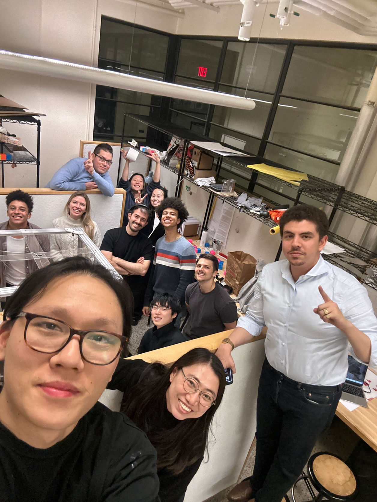
It was a true challenge to design and build one machine within a week. The project could not have been completed without those amazing people from the architecture section!
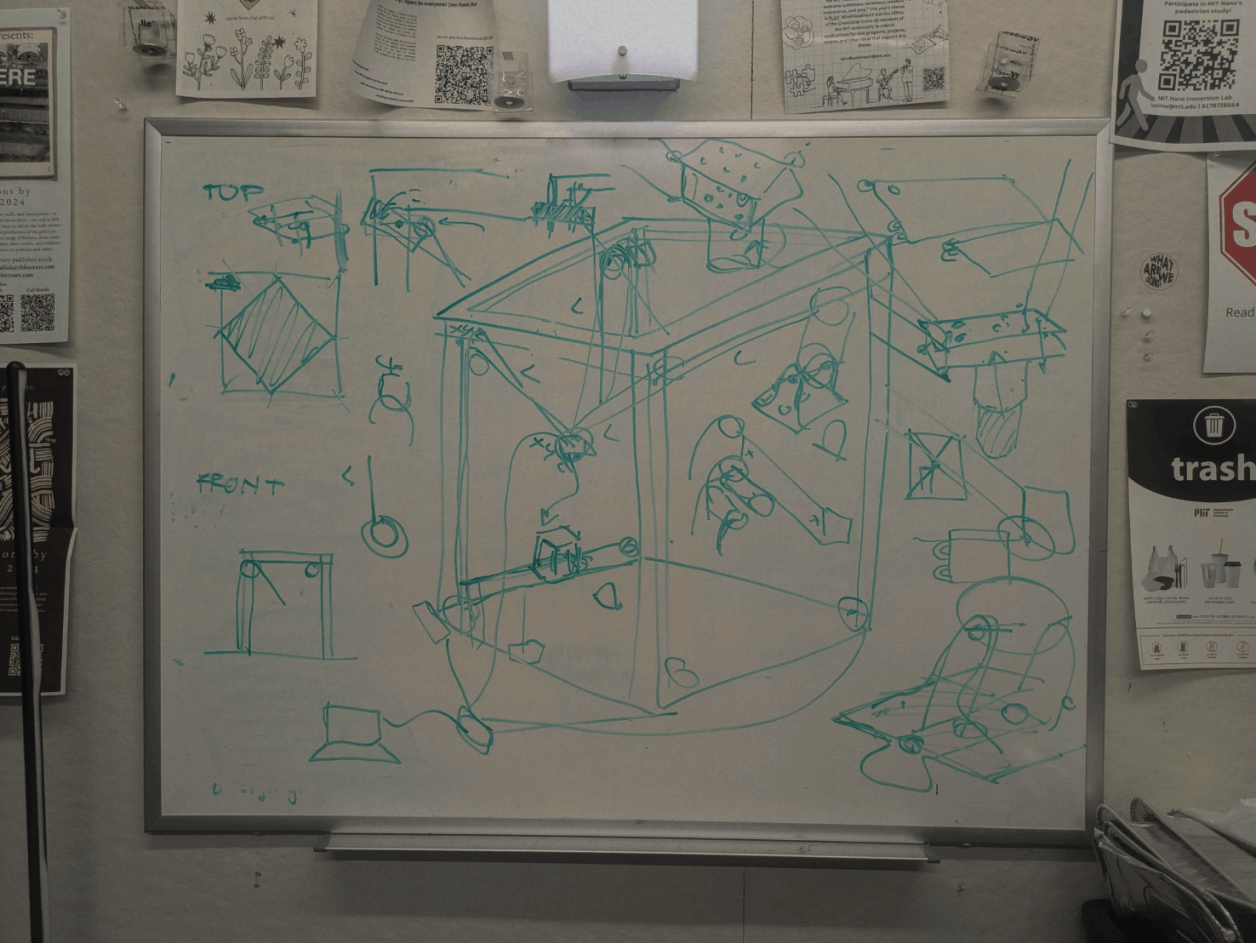
The architecture section moved fast at the beginning thanks to Sergio's clear vision, which united the team and made progress jump-start. Inspired by mechanisms like hang printers and stadium-suspended cameras, Sergio saw this as a chance to test the ideas. Our design resembles a “claw machine,” with a cable-suspended grabber that picks up and arranges blocks within its space.
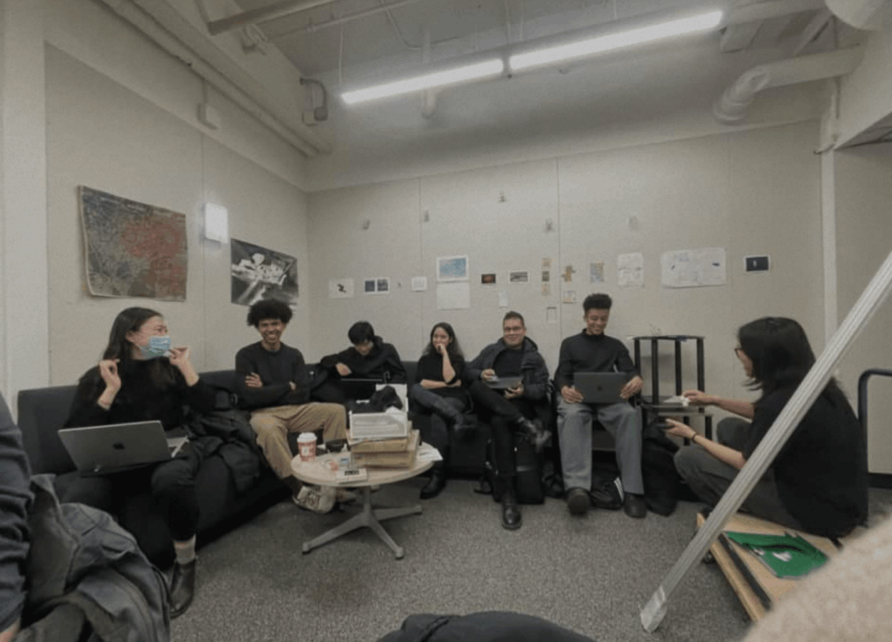
Our group was then split into some sub-groups, including “code”, ” frame", "pulleys","blocks", and "integration." As part of the "frame" team, I am mainly sharing working records from our team.
For full project's website, please refer to this link.
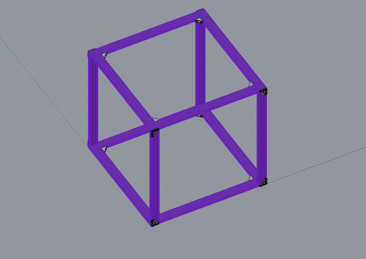
The frame size and design forced decisions for literally every other module, so it was important for them to nail down the design early.
Based on our first brainstorming session, we knew that the frame would be built in the shape of a cube with equal length edges. To ensure a balance between ease of transportation and space to easily attach and manipulate components, the team settled on roughly 32in side lengths.
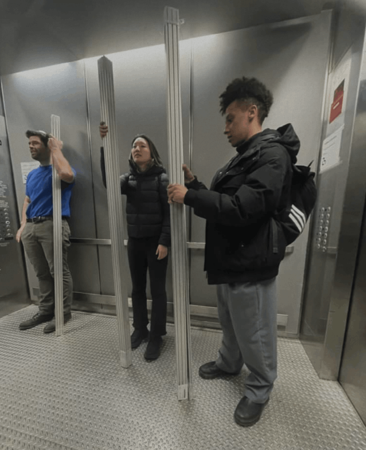
As you can see, they started out MUCH longer than 32in!
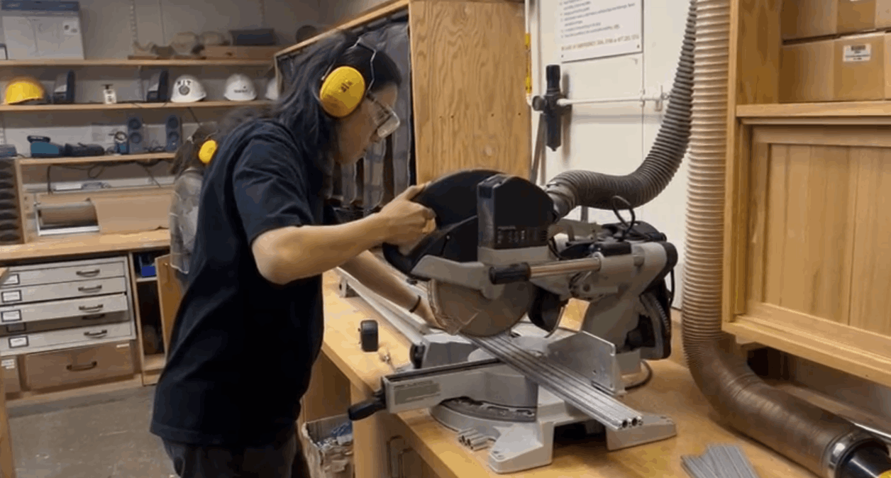
So the first task was to cut them down to size using the circular saw in the architecture shop.
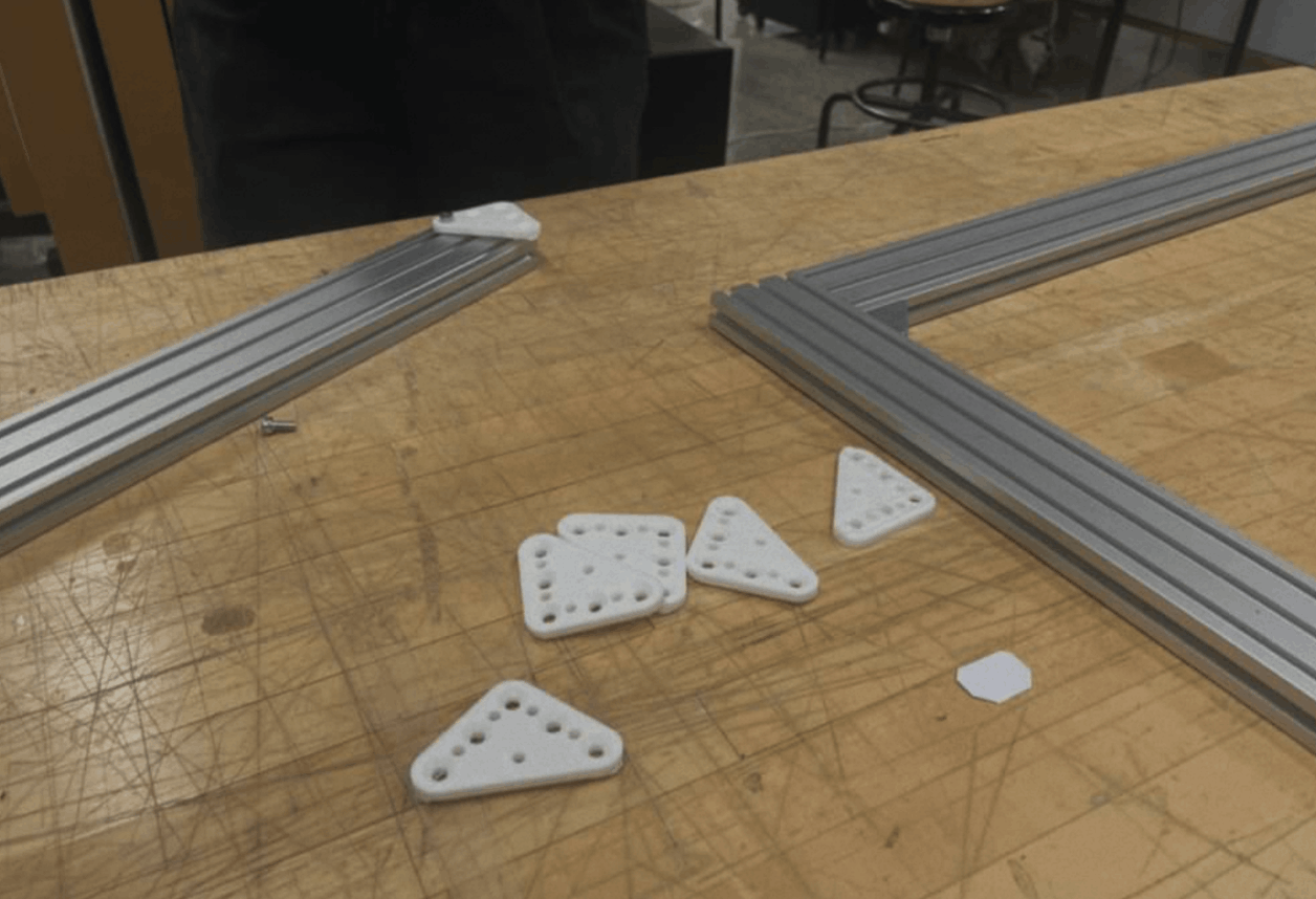
Assembling the frame involved screwing the braces to the extrusions while ensuring everything stayed aligned. To aid in the alignment, our team used metal triangles to ensure perfect right angles around the cube.
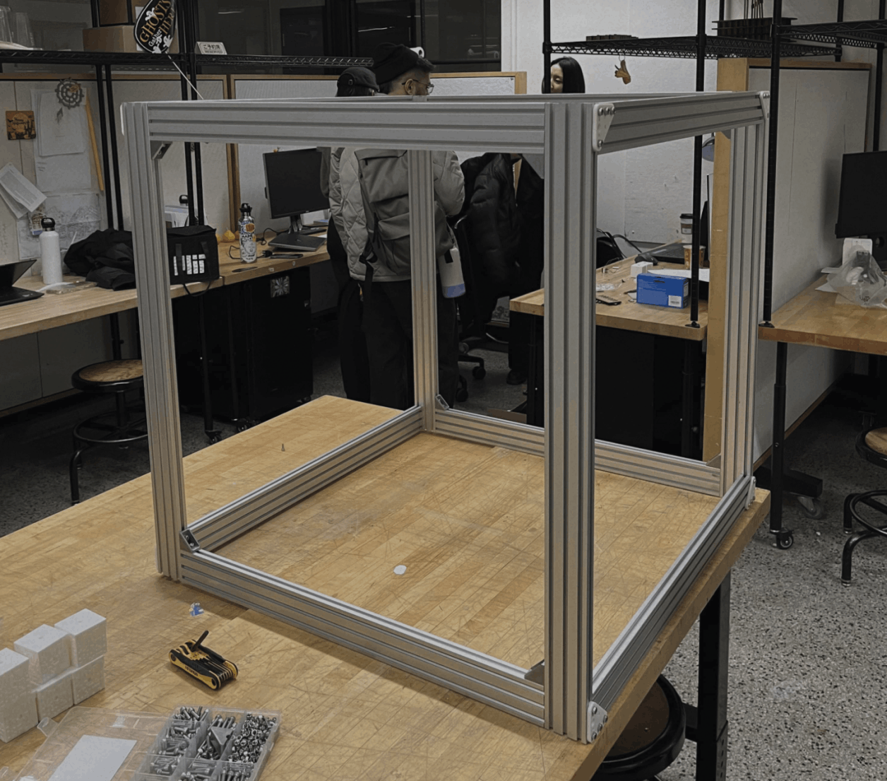
Final assembly took around a half hour and was finished on 11/14. Right on schedule!
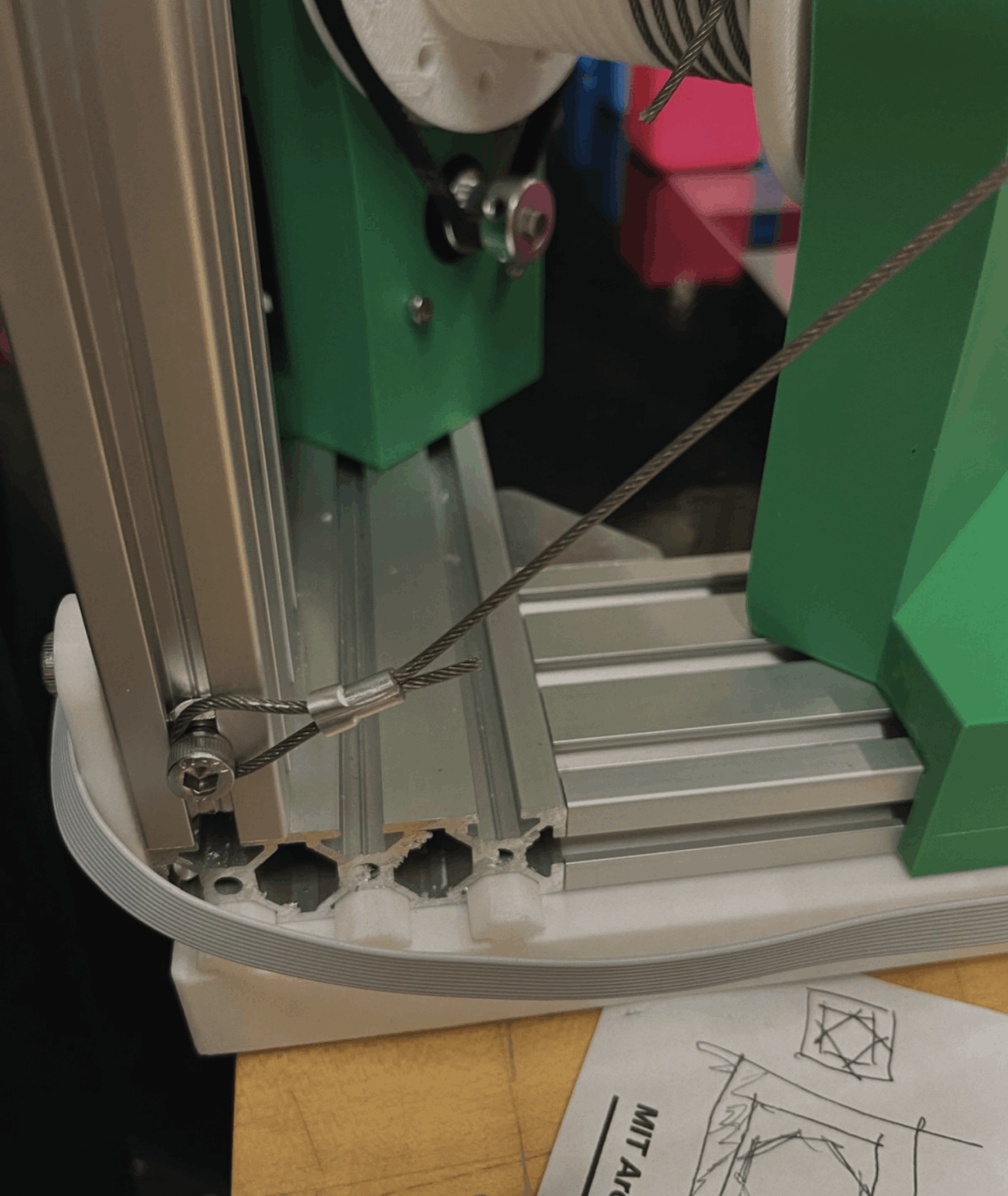
Some final finishing elements were cable cross braces to stabilize the entire frame and a backdrop to hide a lot of the wiring (and add some design flare)
The cross braces were made by crimping cable loops and then using screw holes that could be slotted into the frame
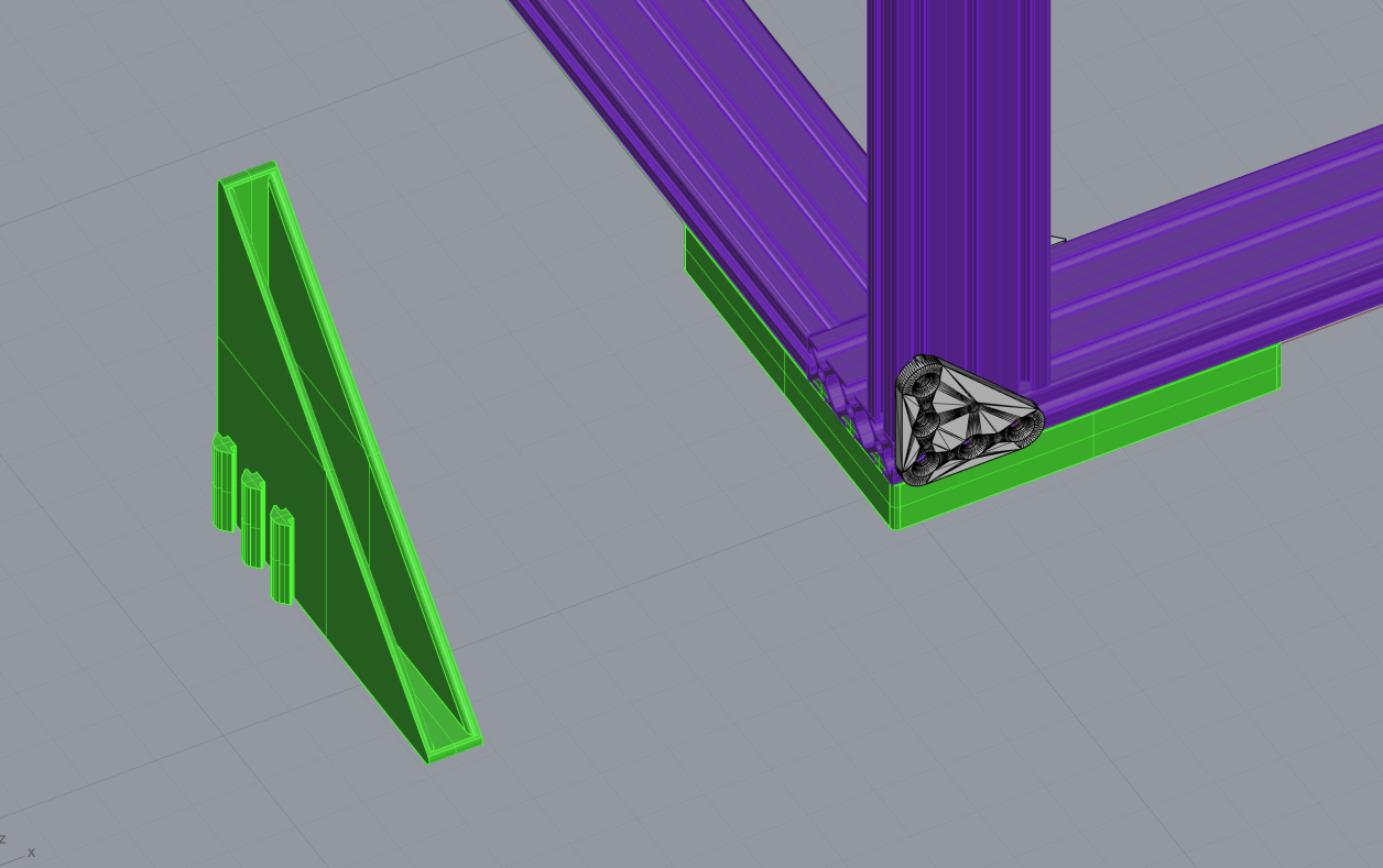
In the spirit of spiral development, and to ensure consistency regardless of what surface we set up on, the frame team also decided to build a base. Here, I designed 4 triangle "feet" to rest the frame on.
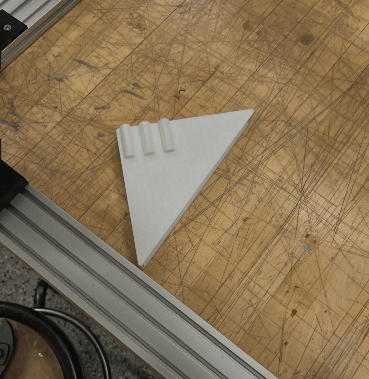
This is the 3D printed results of the base holder. It uses a press fit to slide into the grooves on the extrusion.
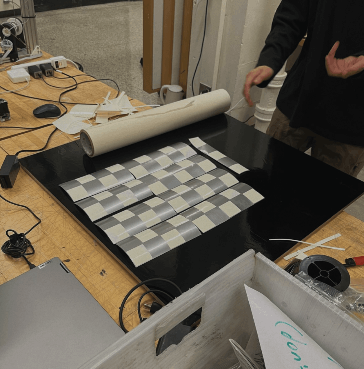
For an actual floor, we covered an MDF sheet in vinyl. The feet have slots for the mdf, so they hold the base in place and don't allow for any movement.
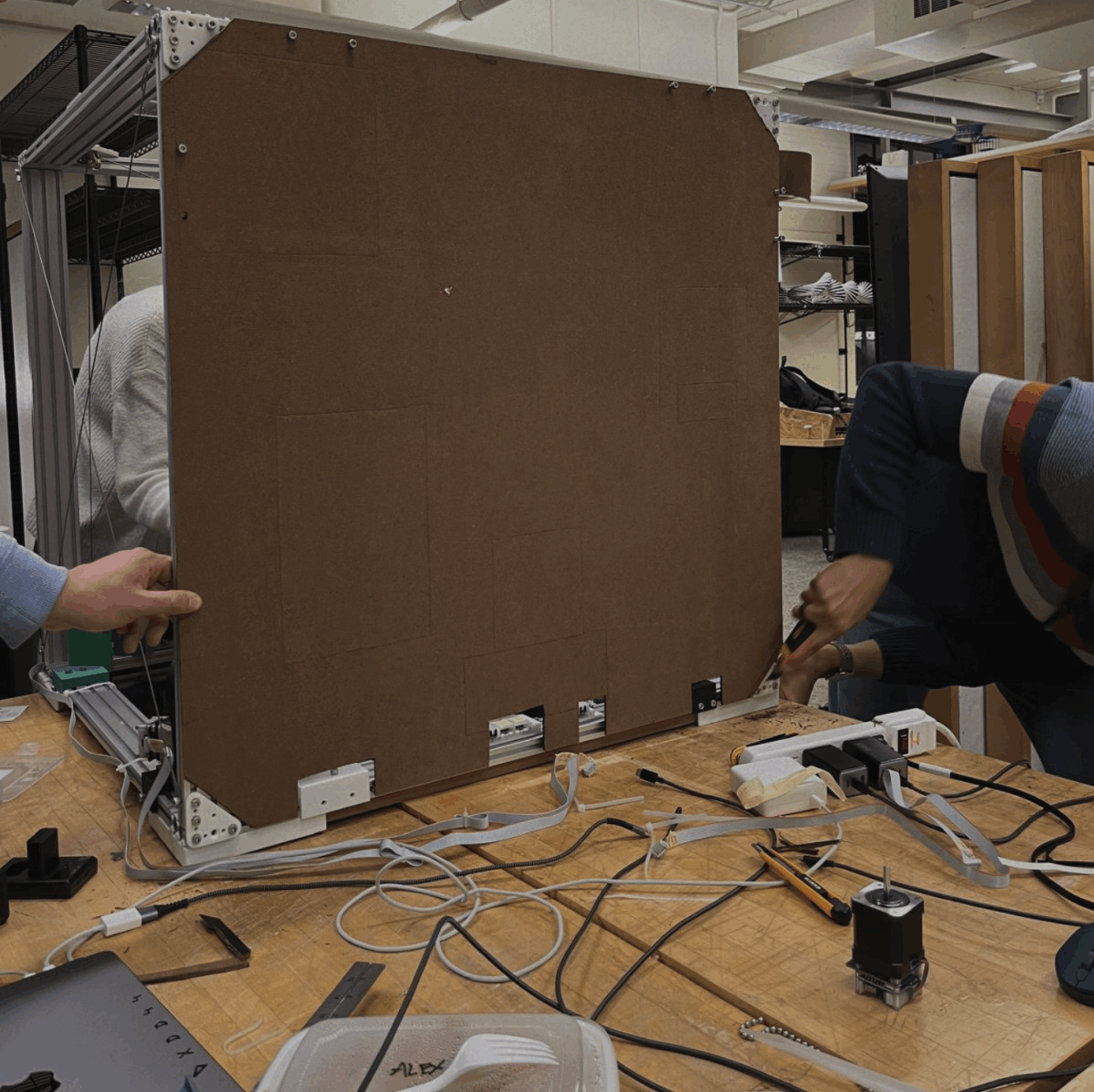
The backdrop was made with another sheet of MDF and painted with our machine's logo. It was then screwed into the back.
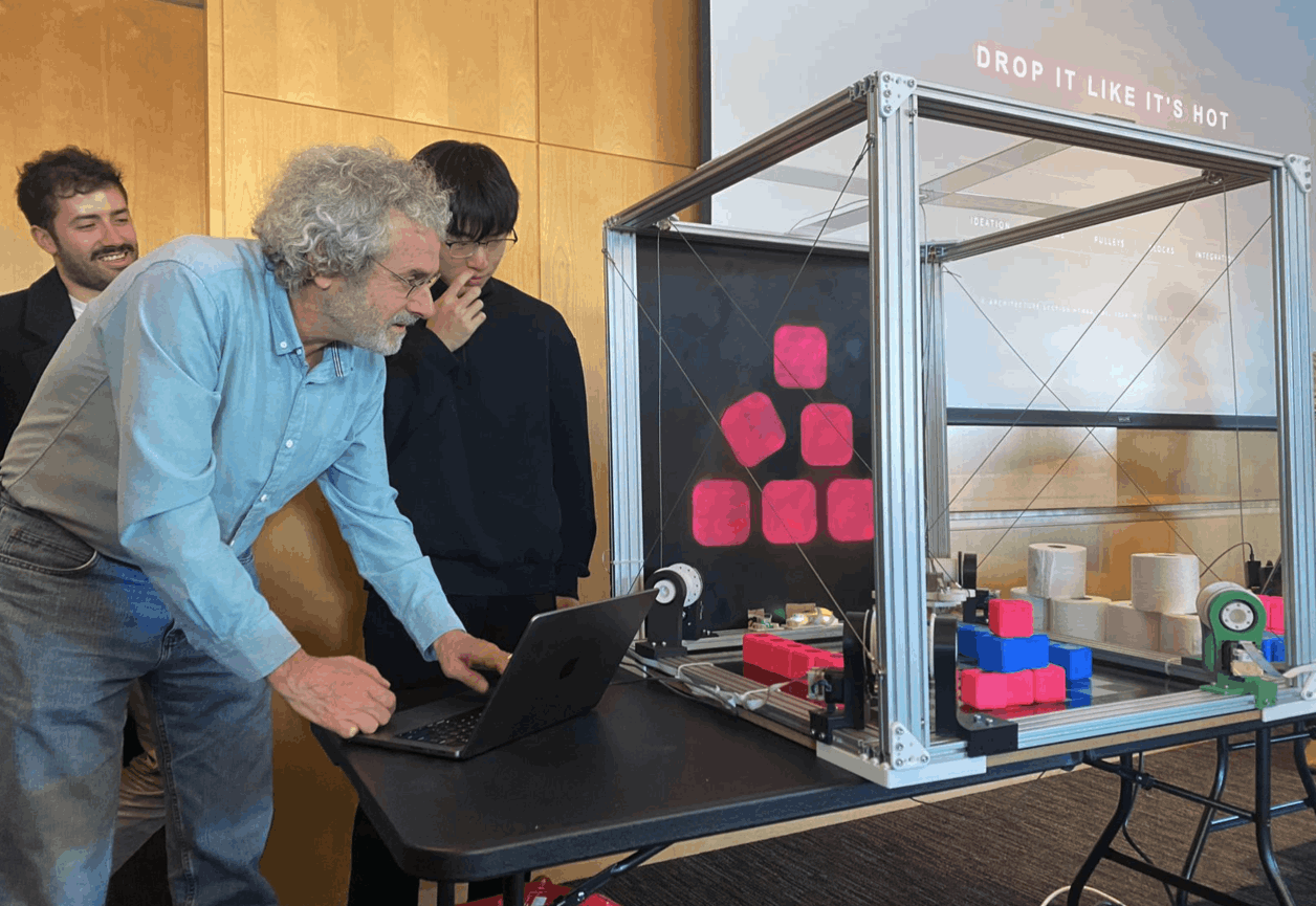
During our demo in the HTMAA class, Neil was also enjoying our machine with us!
Website Software