Mobirise Website Builder

Final Project

Interactive Dual-Pinball Machine


Ray's Interactive Dual-Pinball Machine

Project Sketch

How to make an interactive dual-pinball machine
Mobirise Website Builder
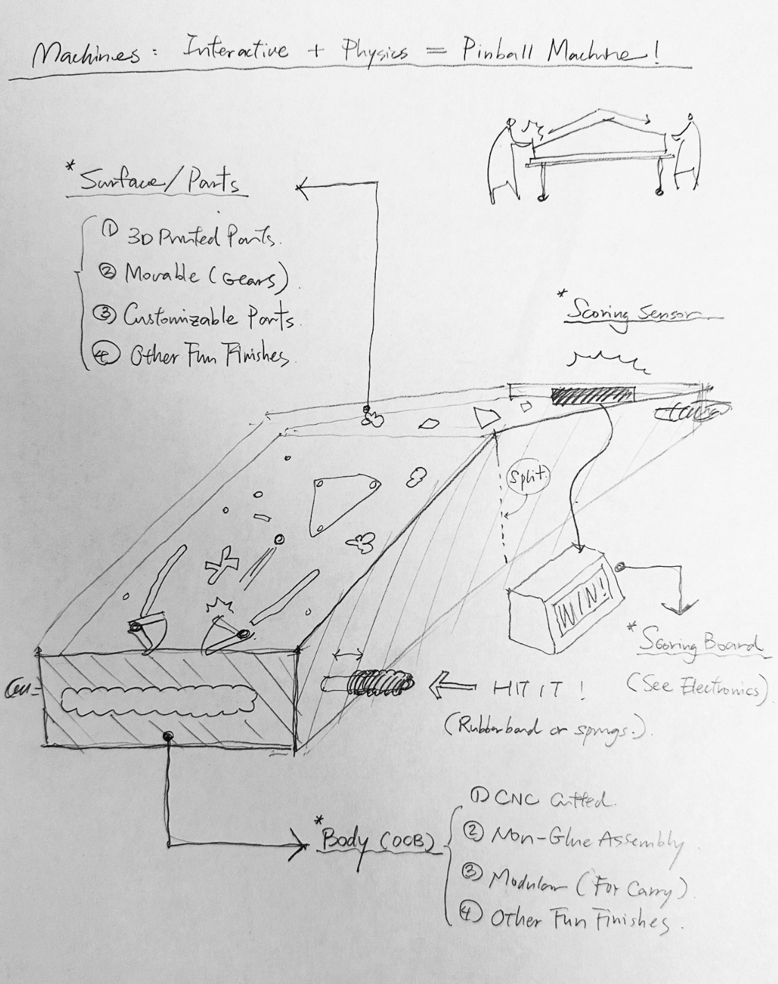
Machine Sketch
Interactive + Physics = Pinball Machine!!

Here are some highlights of the machine's system design:

(A) Surface / Pinball system:

1. 3D-Printed material
2. Movable gears and  (Rotates or Bumps)
3. Customizable flexibility

4. Nice and smooth hitting experience
5. Other fun finishes


(B) Scoring System:

1. Scoring sensor > attach to end of body (step)
2. Scoring board > self-standing part (LED)


(C) Main Body :

1. Large format CNC cutting (OCB)
2. Assembly without glue
3. Modular design (for future carry)
4. Other cool features


Mobirise Website Builder
Electronic Sketch
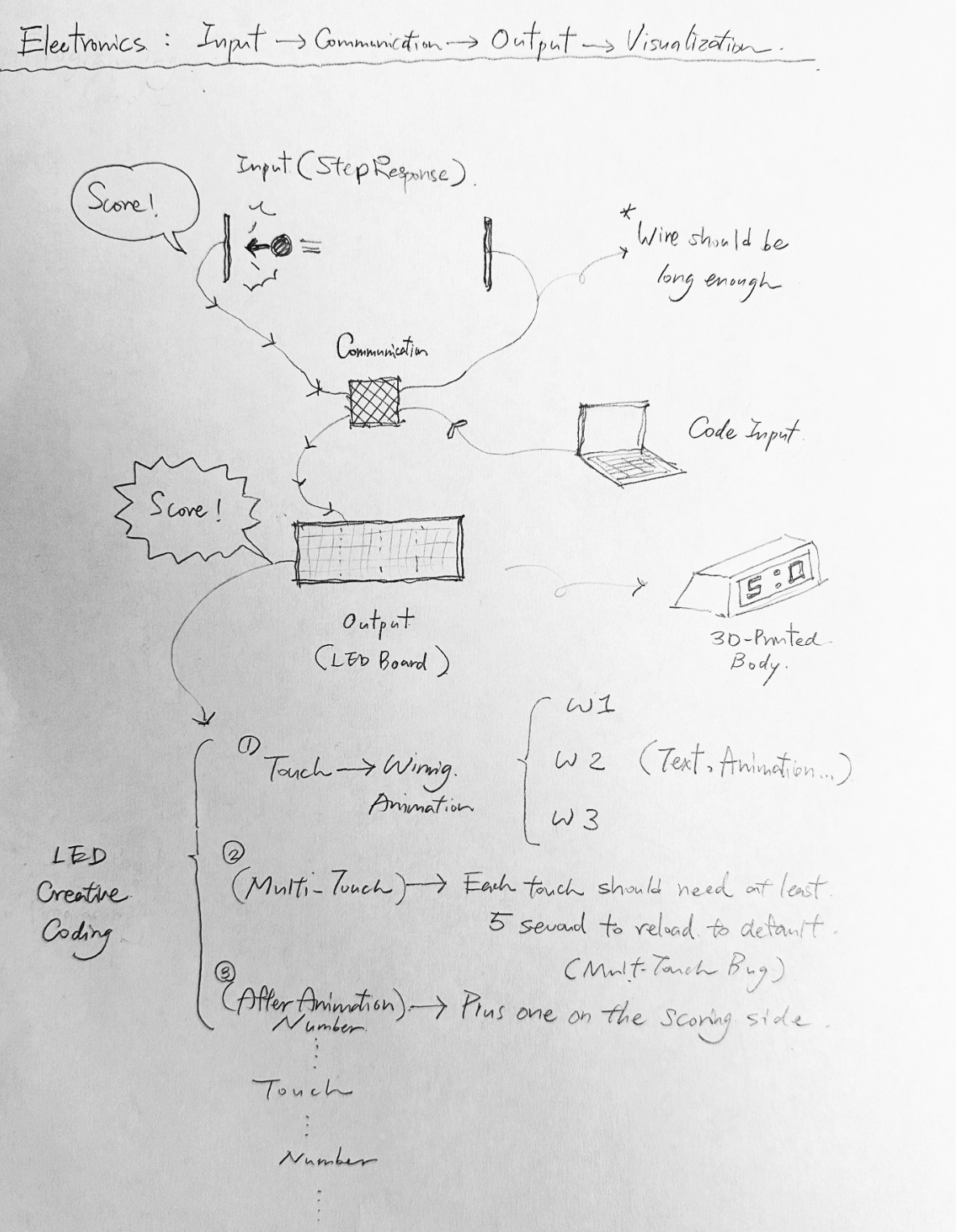
Step Input > Communication > Visual Coding > LED Output

Here are some highlights of the electronic design:

(A) Input:

1. Step response module
2. Detect number
3. Send to board


(B) Network System:

1. Receive data
2. Receive Codes (Creative visual coding)
3. Talk to LED


(C) LED Board :

1. Receive "touch" data: (number>xx)
2. Play a victory animation (random generates 3~5 animations)
3. Wait for 3~5 sec > prevent from multi-touching
4. Reveal score: plus one > reveal number
5. Receive "touch" data......

Machine design

Mobirise Website Builder
Schematic design

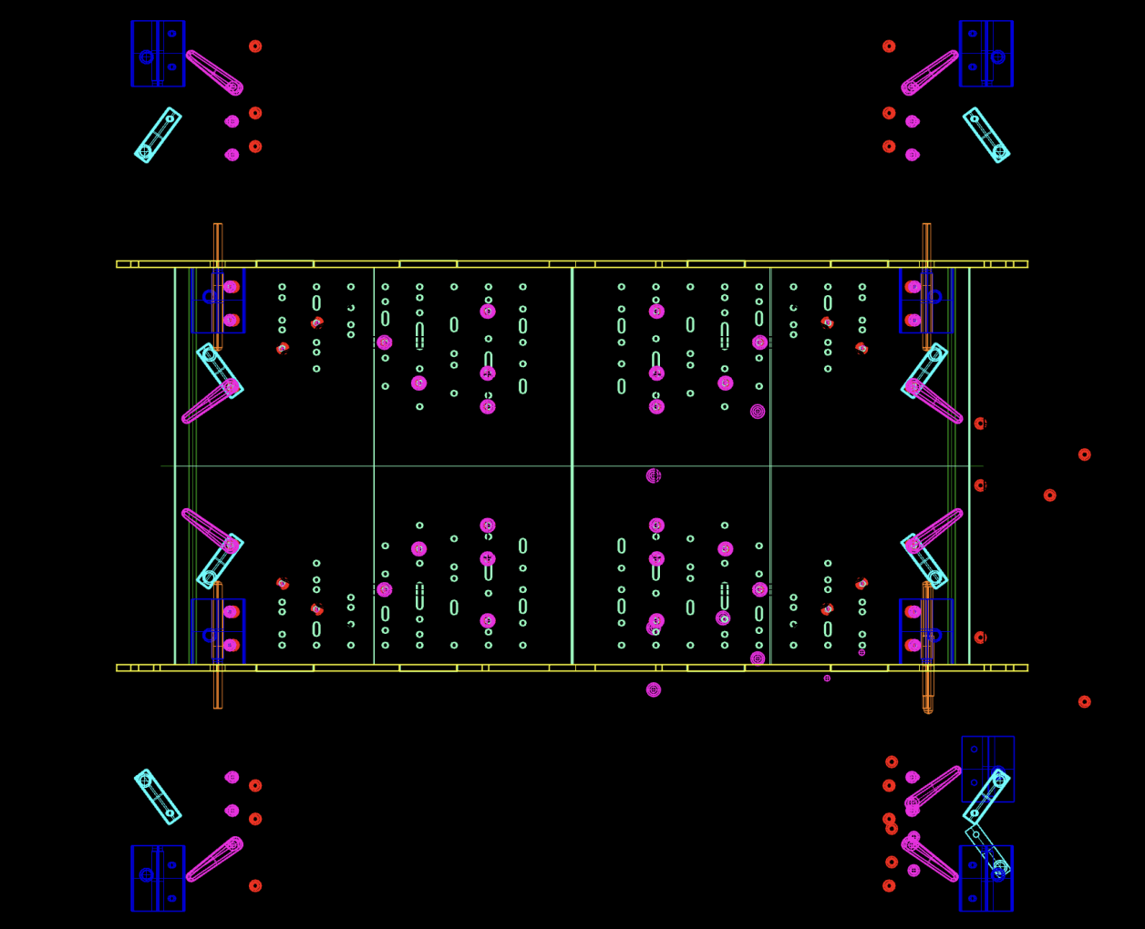
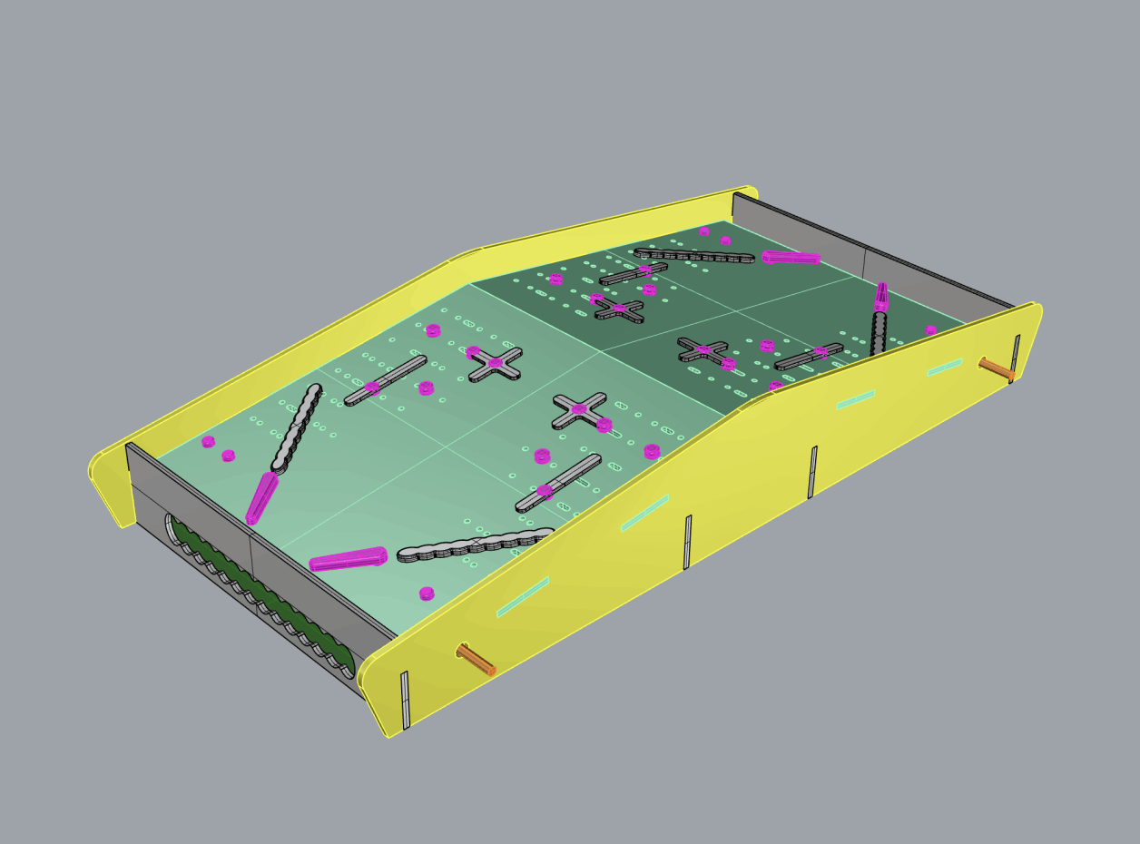
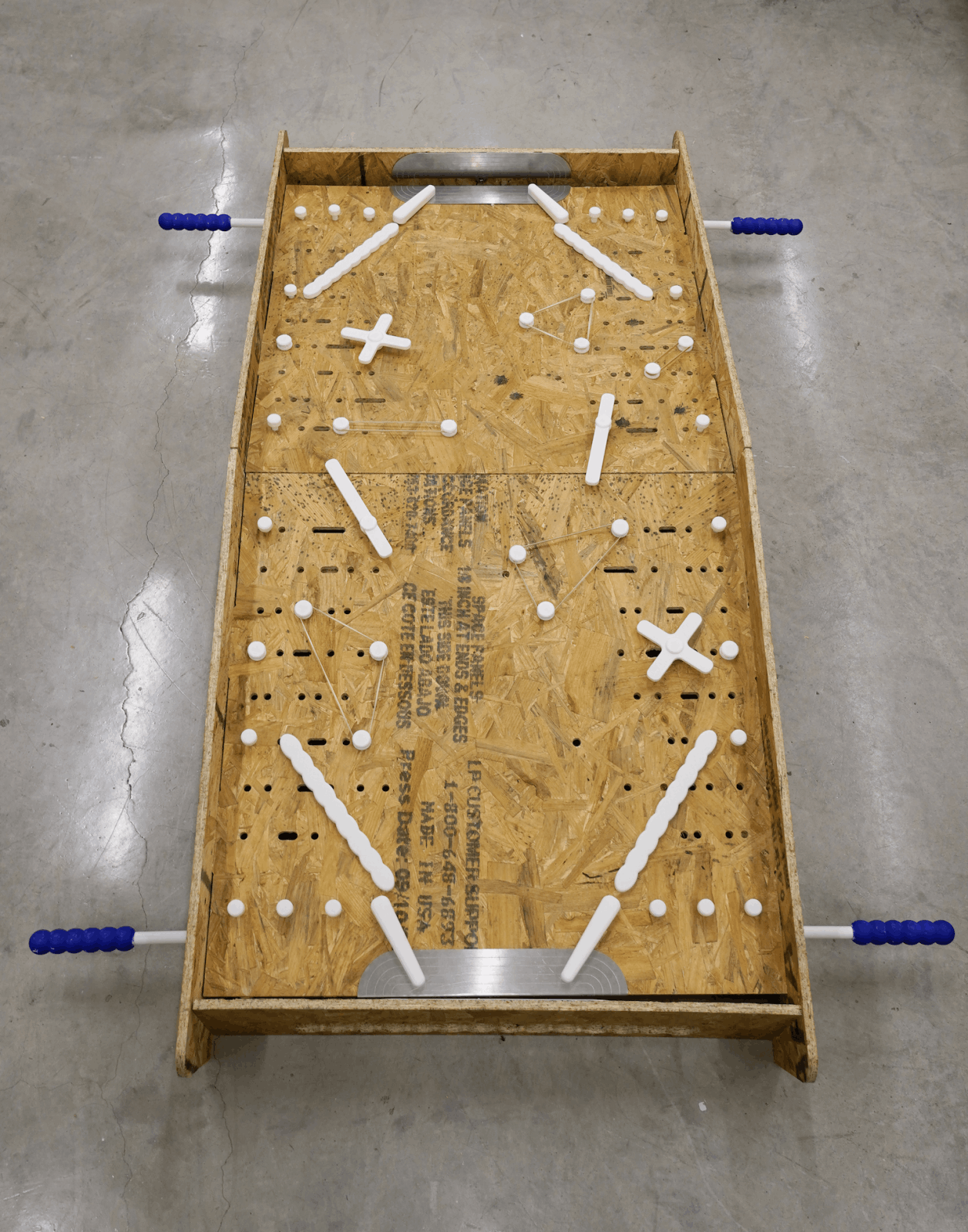
This week's goal is to make something big. Apart from making a meter scale object, I am more interested in making a game machine. Inspired by the dual pinball machine, I drafted the first version of the design in Rhino. 

Mobirise Website Builder
Detailed design

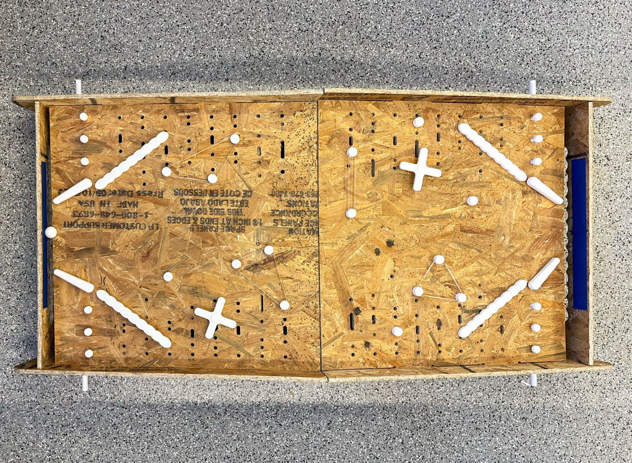
The main body of the machine is OCB, and aim to put things together without any glue. For the machine's surface, I designed a grid system that could enable flexible changes of game design in the future.

Mobirise Website Builder
Board design kit

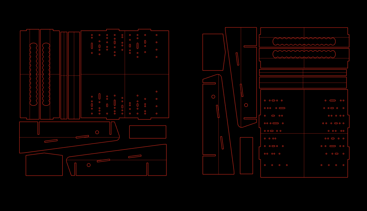
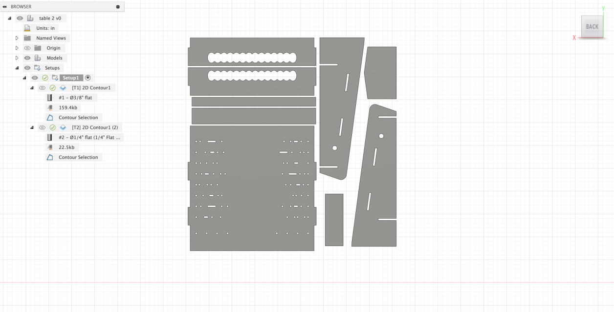
To fit in the CNC machine in the EECS lab, the main body was split in two CNC vector kits.

CNC Machining for machine's body

special thanks to Anthony's help during late night!

OCB Fabrication

Mobirise Website Builder
Kerf dimensions

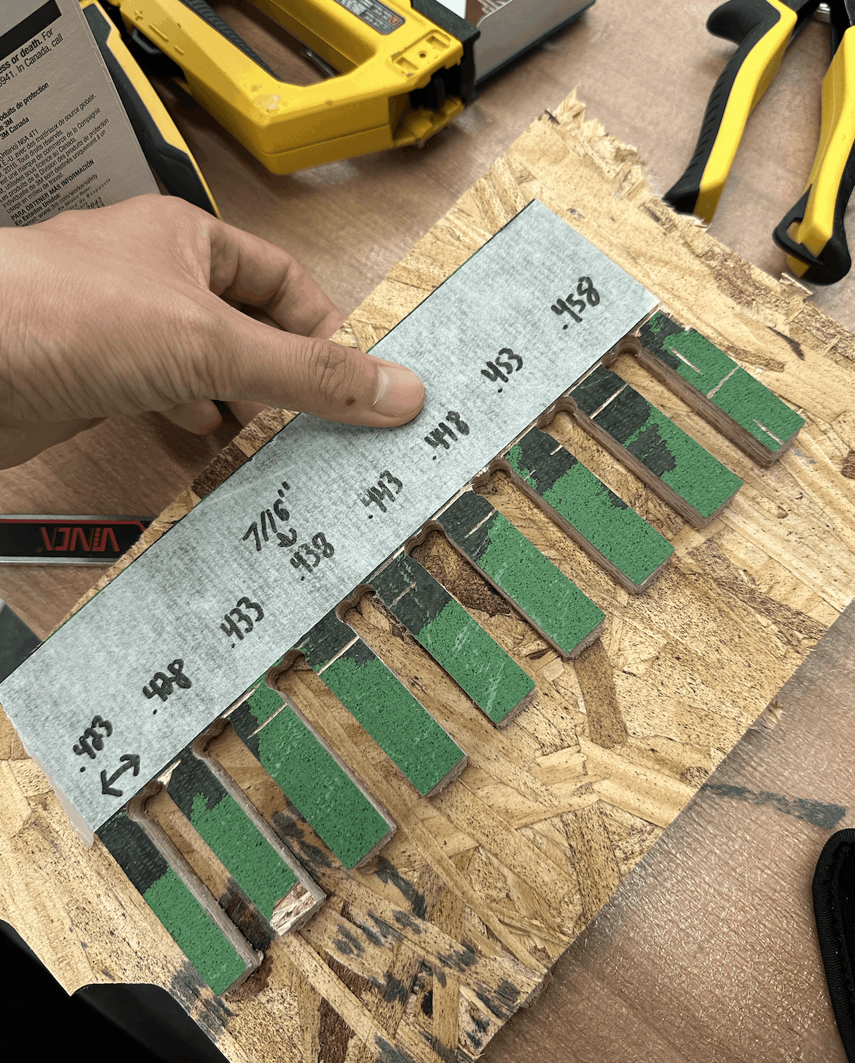
Thanks to Anthony's kerf dimension ruler, we could test out the tightness of the connection when finalizing the construction drawings.

Mobirise Website Builder
Export G-code file Fusion

Importing my Step file from Rhino to Fusion and generating the G-code file based on the machine's nozzle. We're using two different nozzle sizes in order to make the fabrication faster.

Mobirise Website Builder
CNC OCB

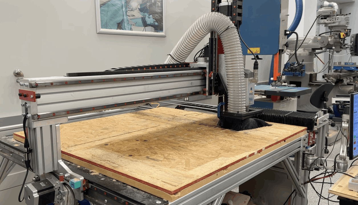
We started the CNC process after nailing the OCB on the machine's table. It only took less than 15 min for each job.

Mobirise Website Builder
OCB cut outs

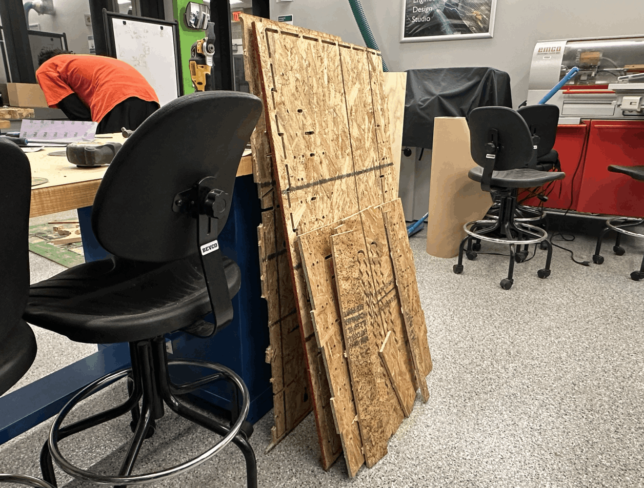
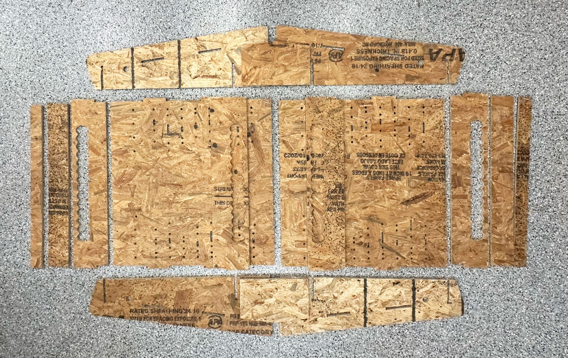
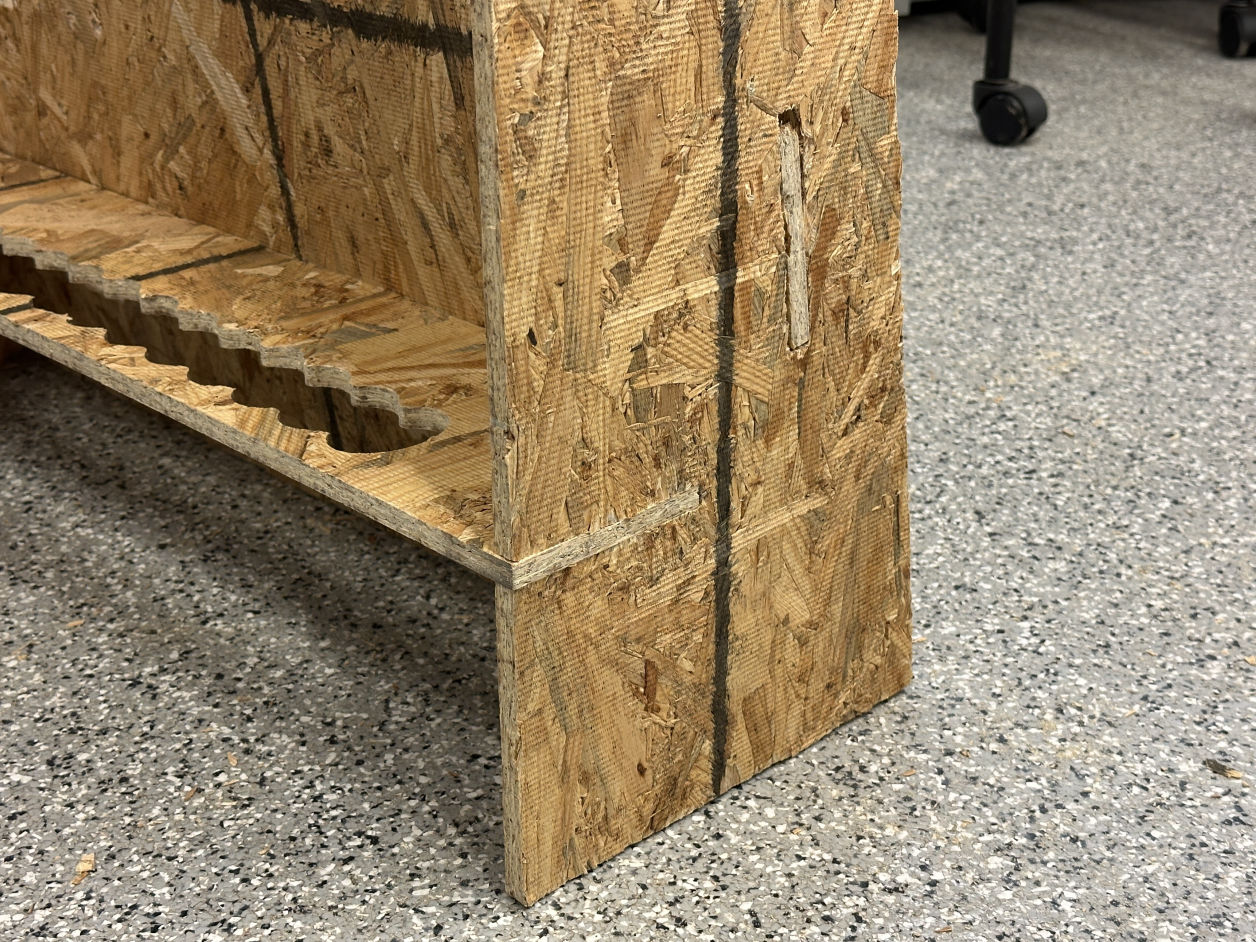
These are the OCB components cut out from the CNC job. After getting all the components, I saw and sanded the components to detach them from the main board since it was attaching the table to prevent it from falling.

Mobirise Website Builder
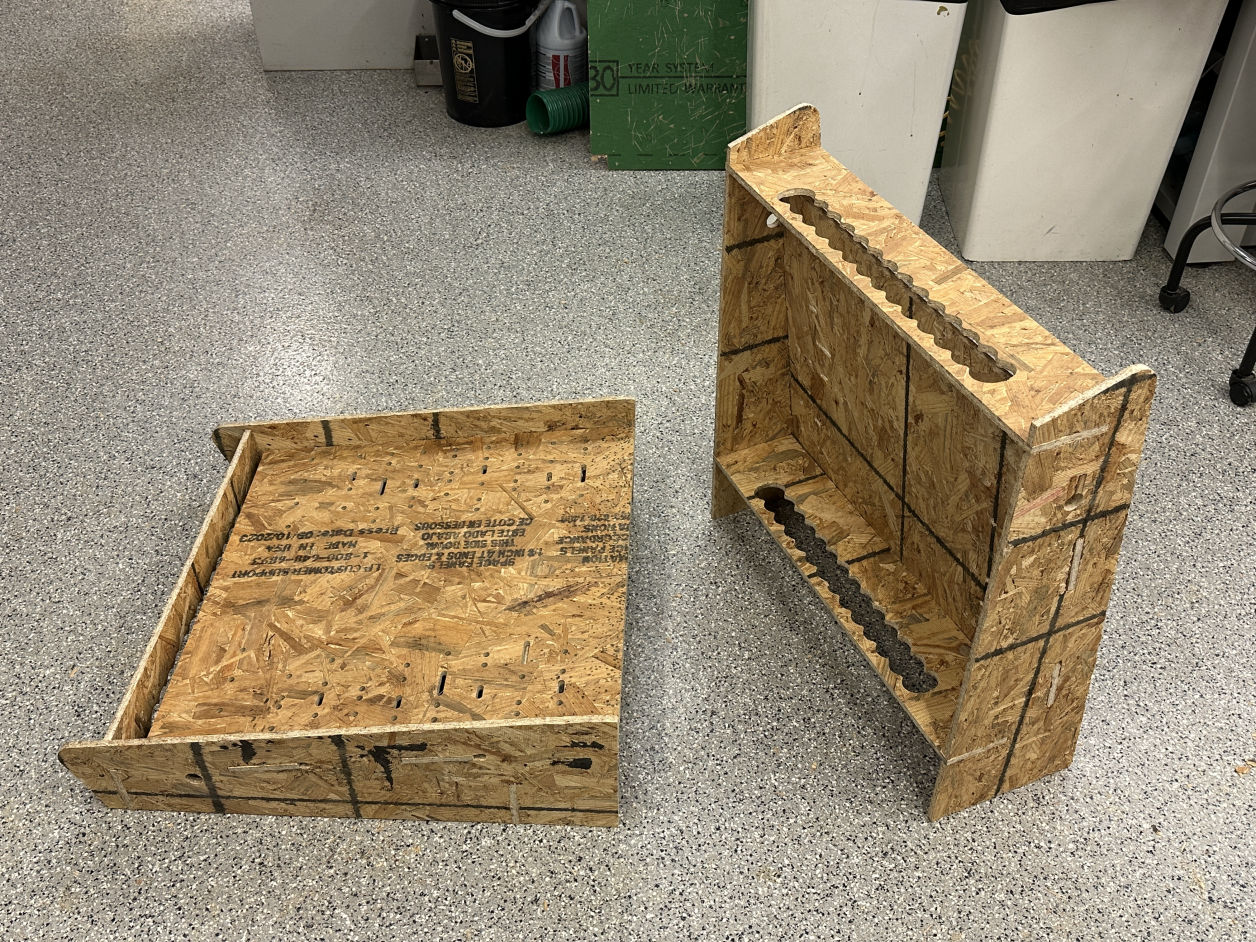
Ready for assembly

Before starting the assembly, I just placed all the pieces together and checked the dimensions again. I actually found some inaccurate parts during this process and fixed them before the assembly.

Mobirise Website Builder
Joint without glue

After a bit of sanding process, the parts went together pretty well; it was tight enough to be rigid without any glue's help.

Mobirise Website Builder
Assemble it twice

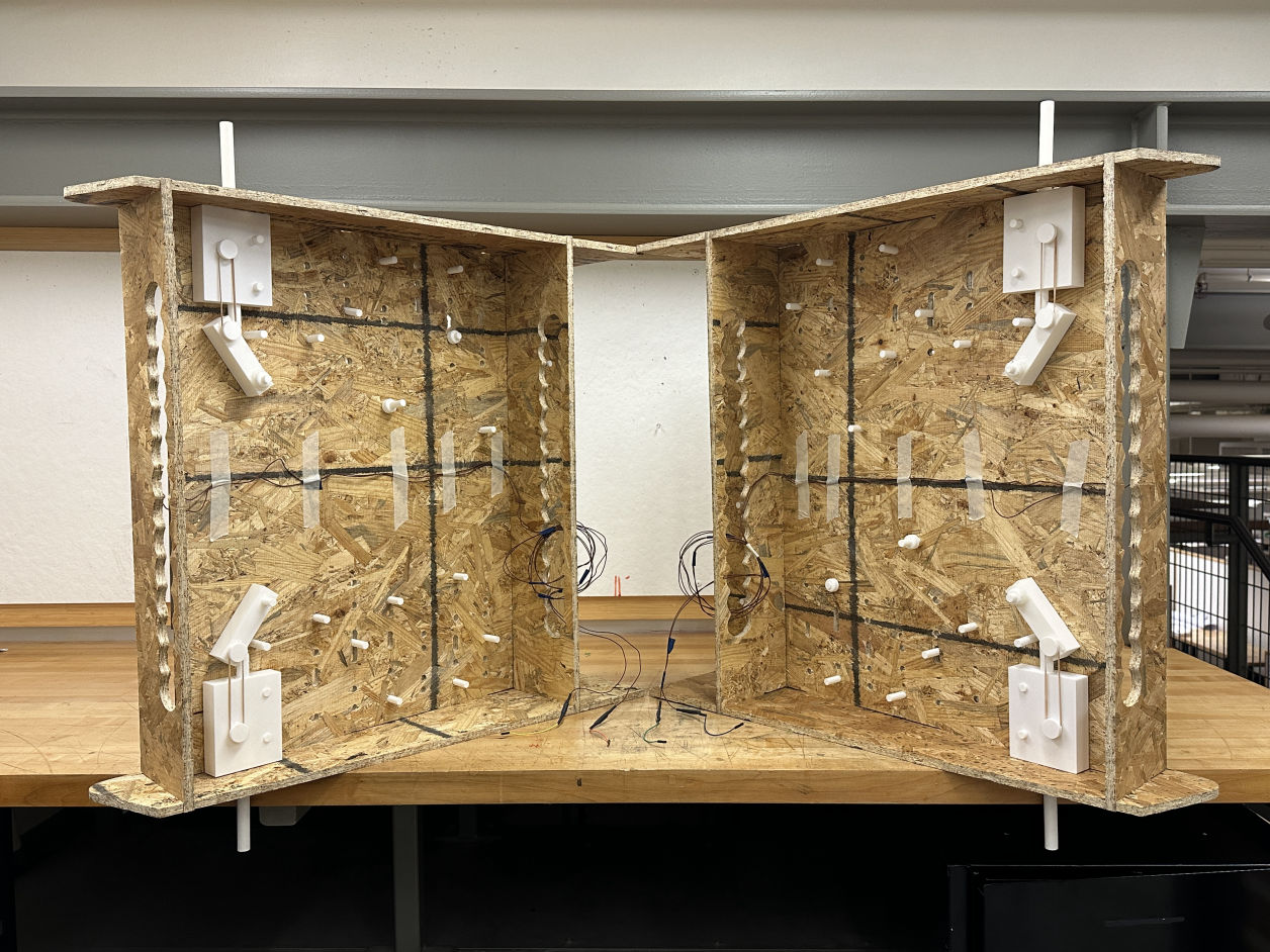
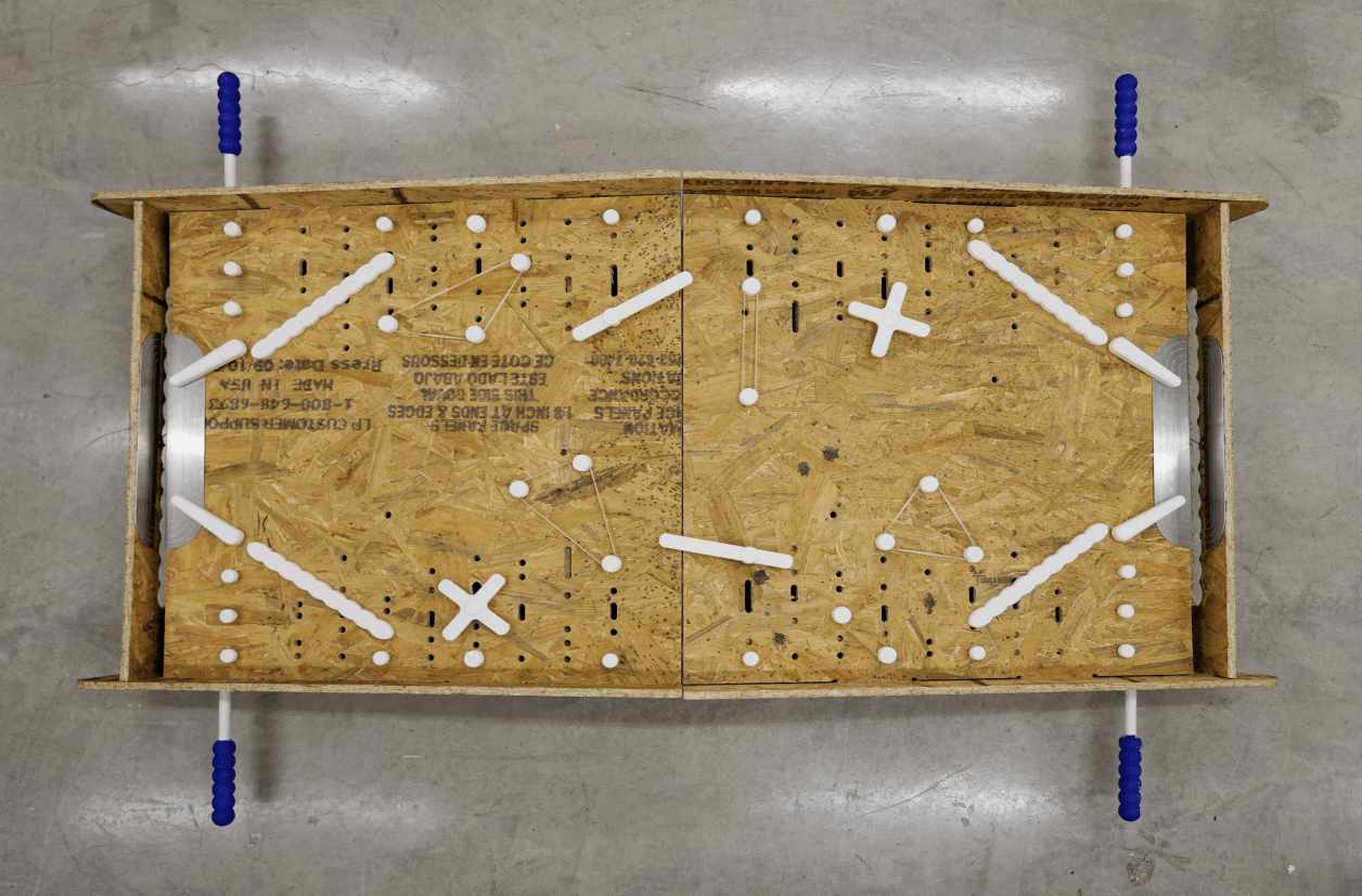
Based on the game rule, two table units should be touching each other to play. Thus, in this week, I rapid-manufactured two pieces of big things.

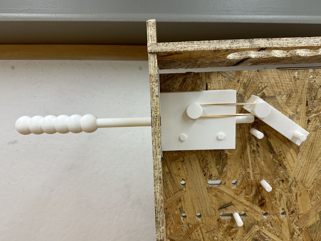
Flipper system design with 3D prints + rubber band

Pinball system

Mobirise Website Builder
Components design

In Rhino, I also designed all the small components for the pinball machine. These components are not just for decorations but have different mechanism to move around.

Mobirise Website Builder
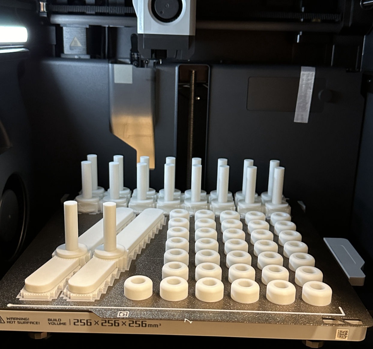
3D Print the joints

Standardized bolts and joints for the pinball machine. For the next generation of the machine, I would try to use some existing bolts instead of 3D printing all of them.

Mobirise Website Builder
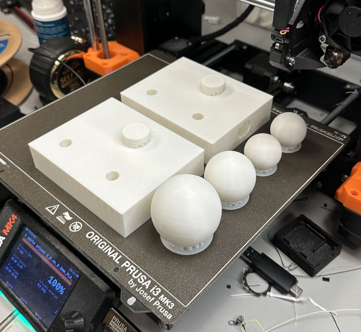
3D Print the flippers and balls

Printing different sizes of balls (including the standard size and some bigger gigs) and the flipper's body that will attach to the table.

Mobirise Website Builder
Final assembly

Most of the 3D prints were put together smoothly. However, it was broken once due to the torch and the tightness of the flipper box. The adjusted version was assembled right before Wednesday's class, so close!

Mobirise Website Builder
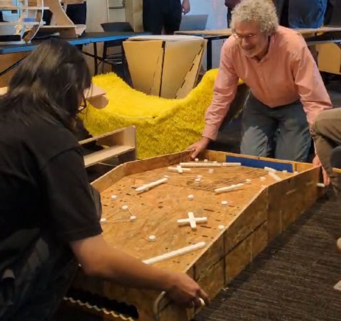
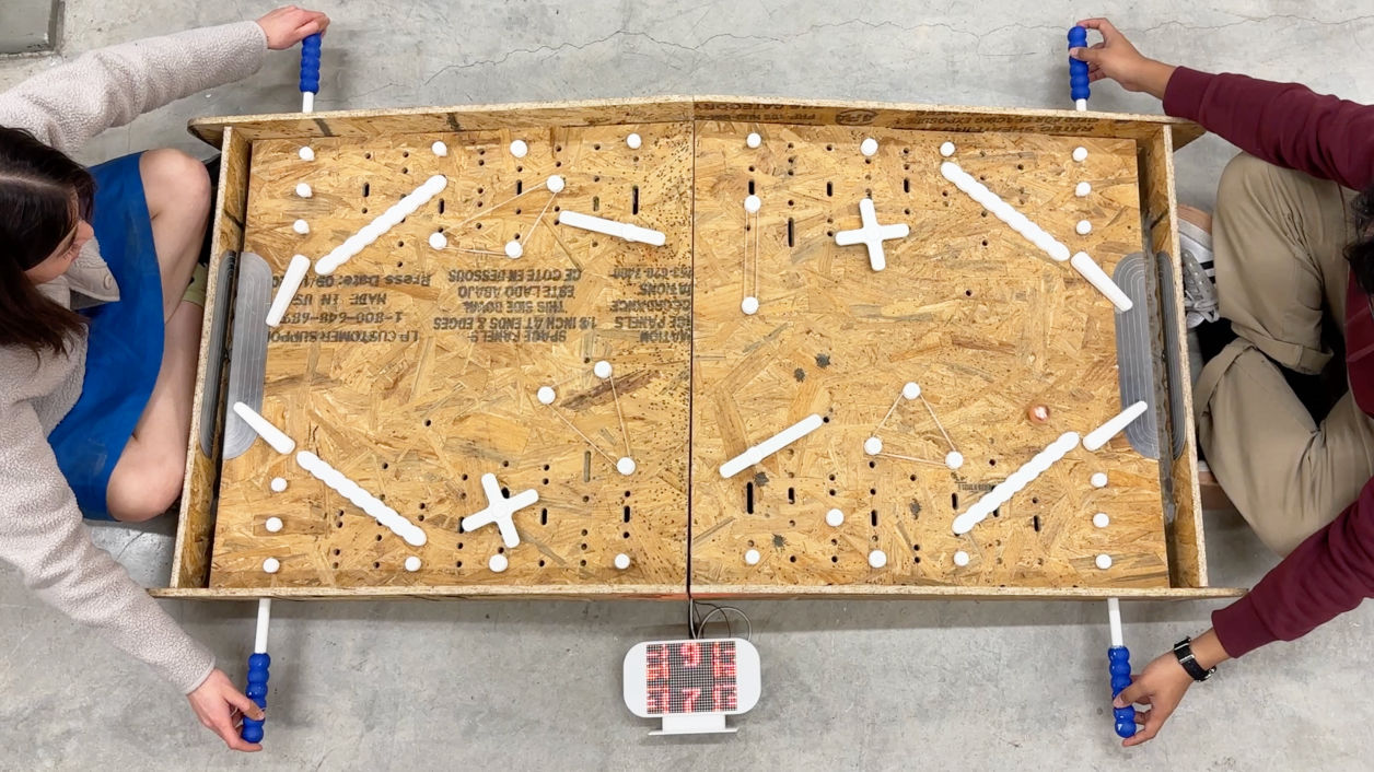
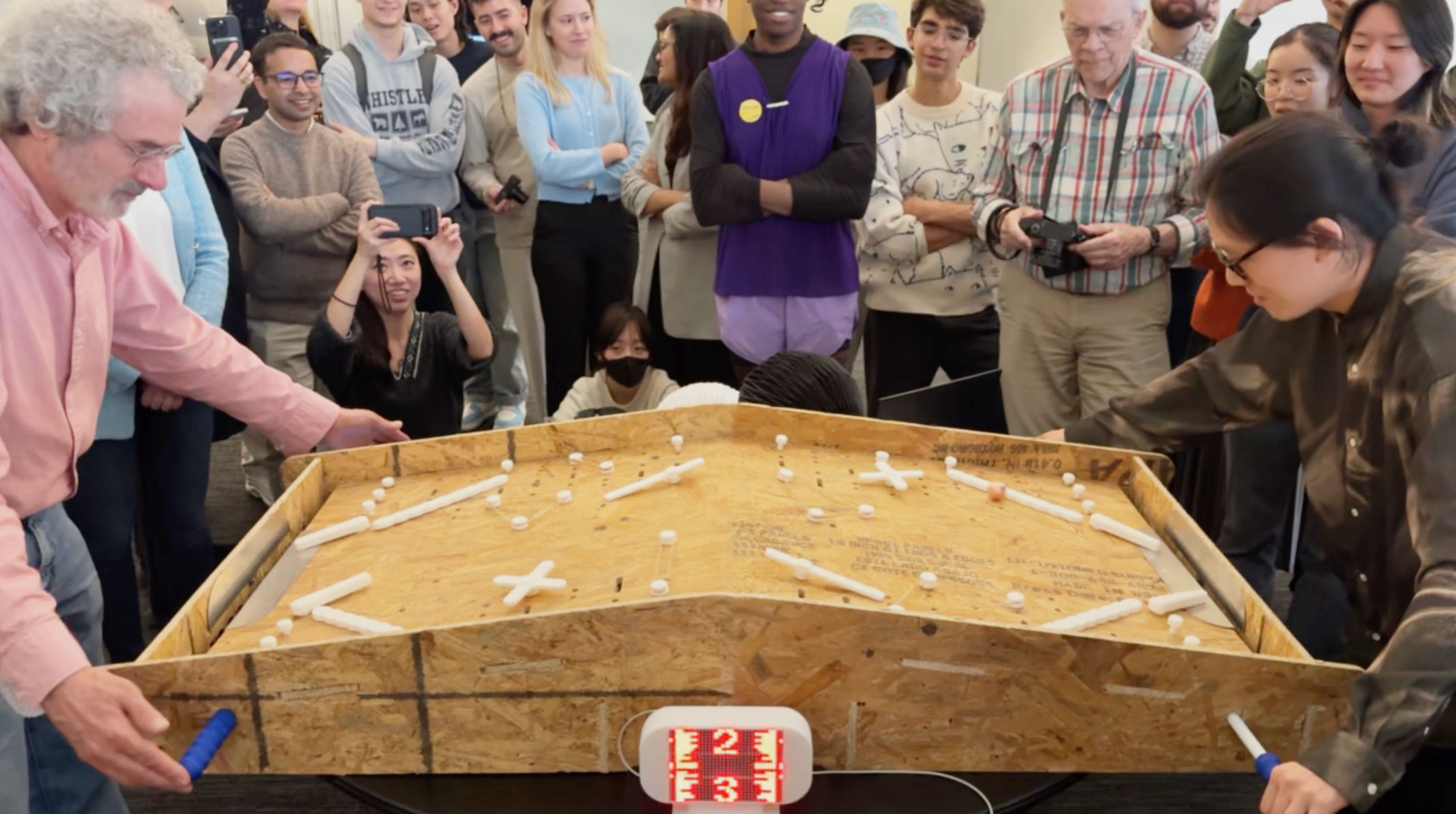
Playing Gen-One machine with Neil

During the class, I was playing the first-generation pinball machine with Neil. It was really fun, but I also found some parts can be improved. 

The optimizations are noted below.

First-Generation: Playing pinball machine with Neil

1 : 0

Mobirise Website Builder
Ergonomic optimization

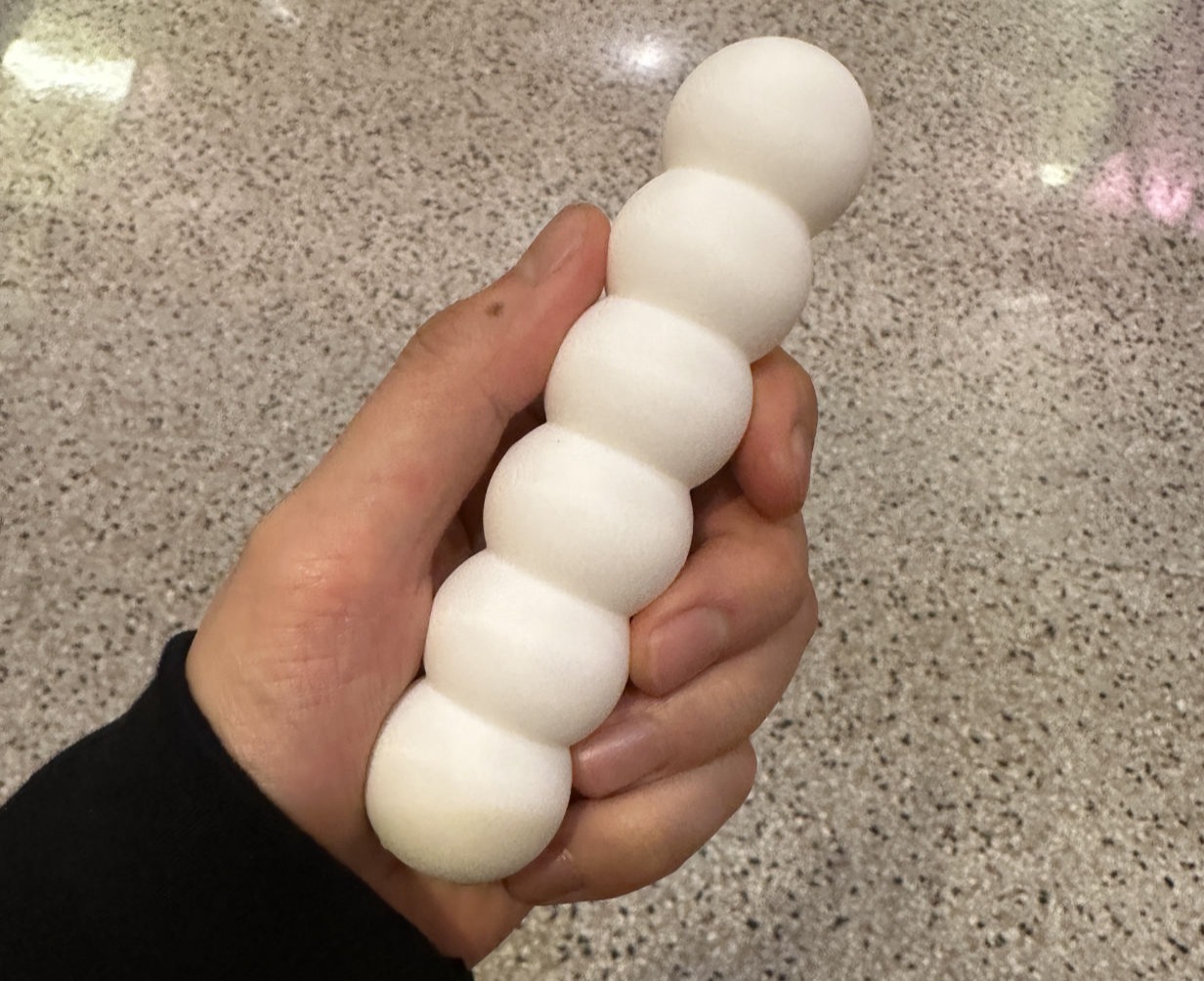
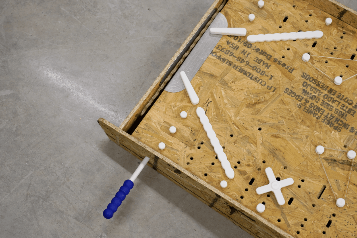
It was hard to hit the flipper with only one finger, so I designed handles that are much easier to grab and play with!

Mobirise Website Builder
Mechanical optimization

The machine was not strong enough due to the limited length of the bar. As the length was extended and the handle was improved, you can hit it hard without any hesitation!

Mobirise Website Builder
Design optimization

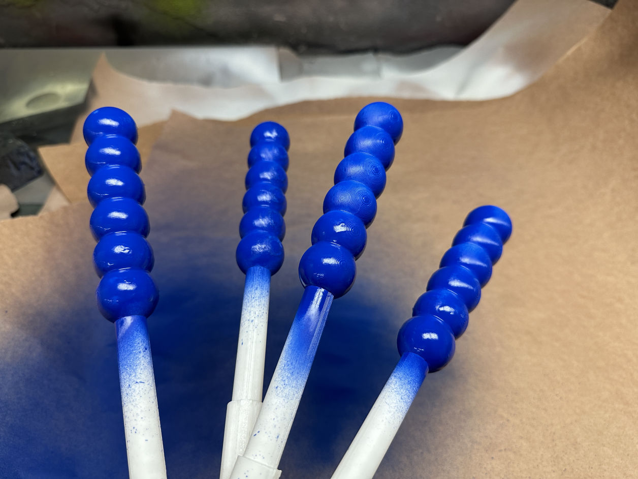
Adding some blue spray on top of my handle was kind of a random decision. It would actually be better if I just printed or cast in the blue material so that the coating would be sustainable. 

Mechanical Optimization

Electronic Design

How to make an interactive dual-pinball machine
Mobirise Website Builder
Electronic Sketch
Step Input > Communication > Visual Coding > LED Output

Here are some highlights of the electronic design:

(A) Input:

1. Step response
2. Detect number
3. Send to board


(B) Network System:

1. Receive data
2. Receive Codes (Creative visual coding)
3. Talk to LED


(C) LED Board :

1. Receive "touch" data: (number>xx)
2. Play a victory animation (random generates 3~5 animations)
3. Wait for 3~5 sec > prevent from multi-touching
4. Reveal score: plus one > reveal number
5. Receive "touch" data......

Mobirise Website Builder
Microcontroller

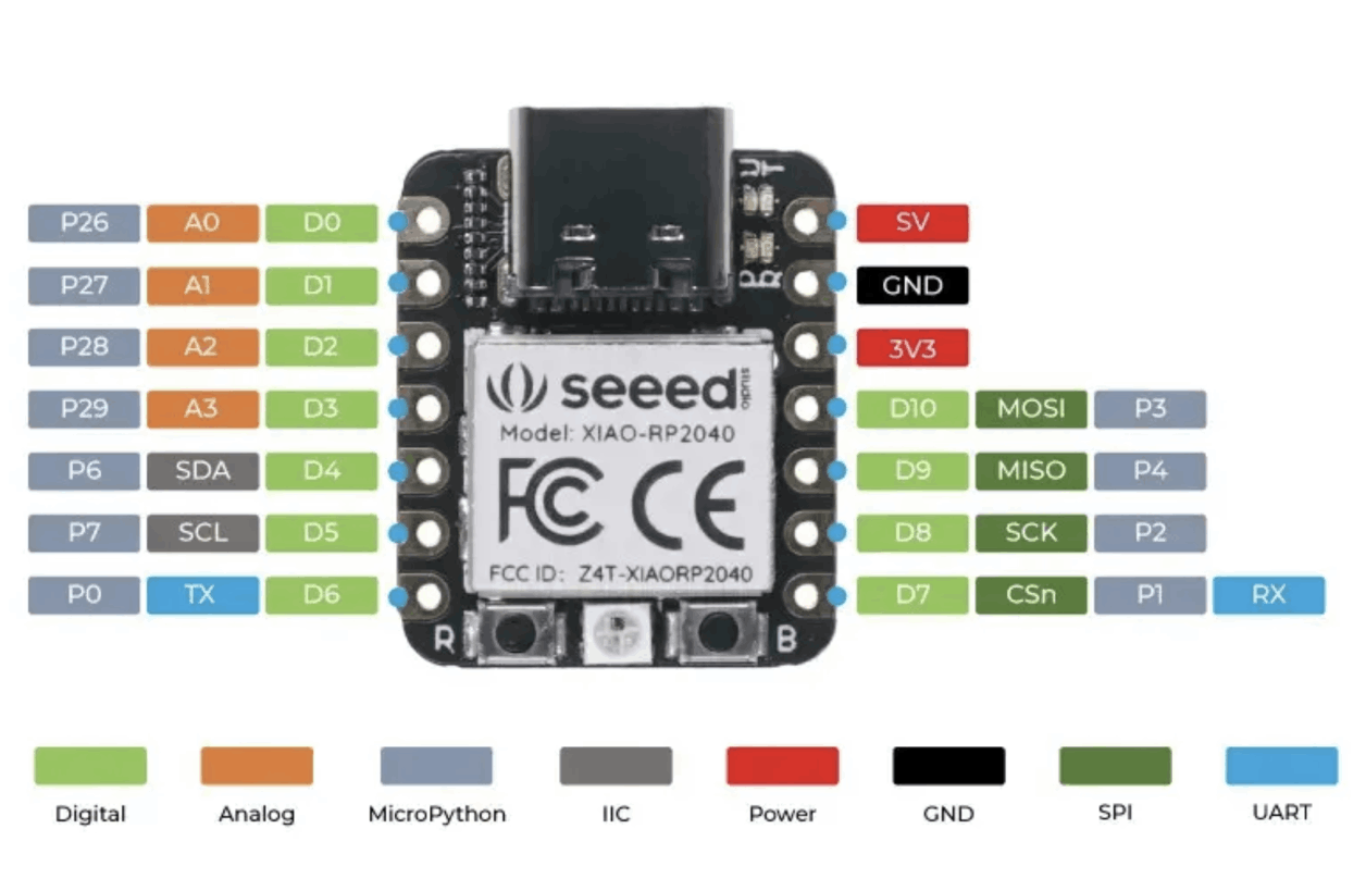
The schematic for my system is quite straightforward, and everything can be controlled by only one microcontroller. I am using XIAO SEEED STUDIO RP2040 due to it's much more reliable than the ESP series!

Mobirise Website Builder
Schematic Design

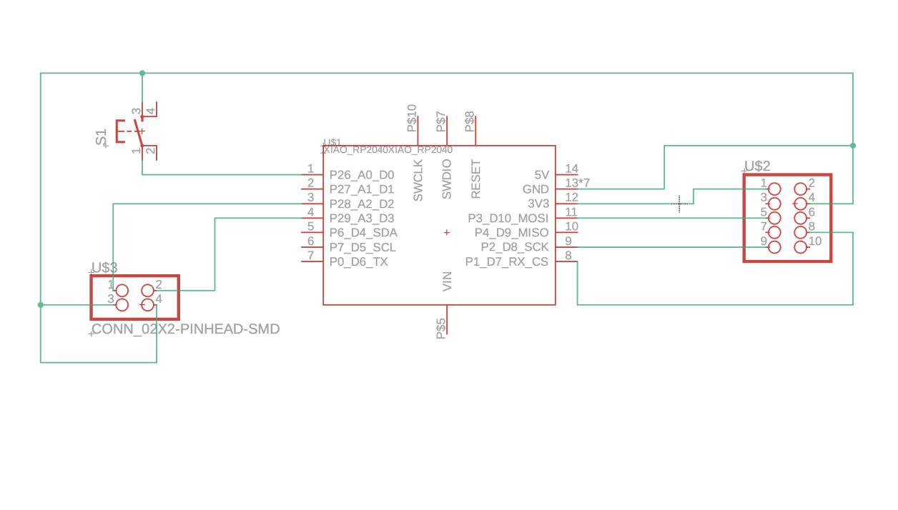
The input signal will sent to D2 and D3 once the end of factor is connected by an iron pinball. Once the microcontroller reads the message, it will talk to the LED matrix through the pins shown on the right. An extra button was added just in case of any future adjustments.

Mobirise Website Builder
PCB Design

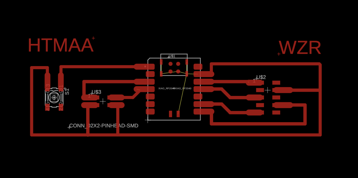
Based on my own experience, soldering often fails when the footprints are too small. Thus, I optimized the footprints to make them easier to access or keep distance from potential shorts.

WZR and HTMAA is a must!

Board Production

Mobirise Website Builder
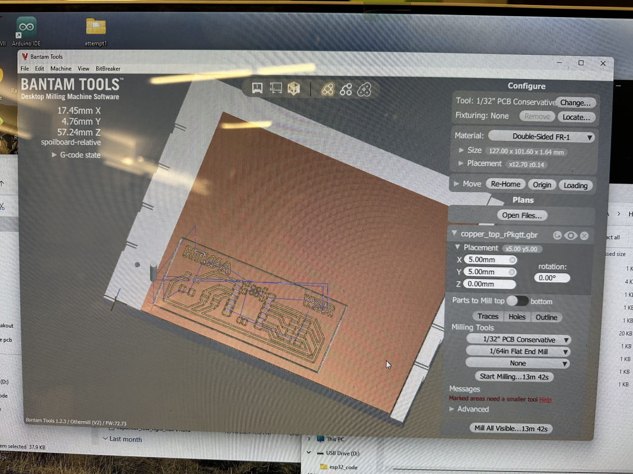
Import Gerber File

Importing my gerber files to the Bantam tools. It consists of one profile file for the board's outline, and one copper top milling file.

Mobirise Website Builder
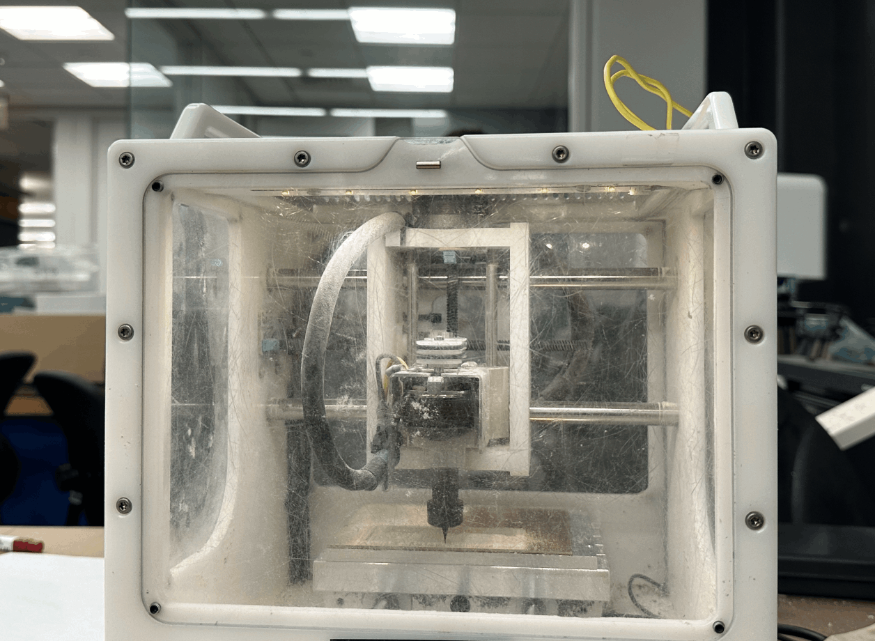
Starting the Job

While choosing the 1/32'' and 1/64'' end mills, we need to change the tools during the jobs.

Mobirise Website Builder
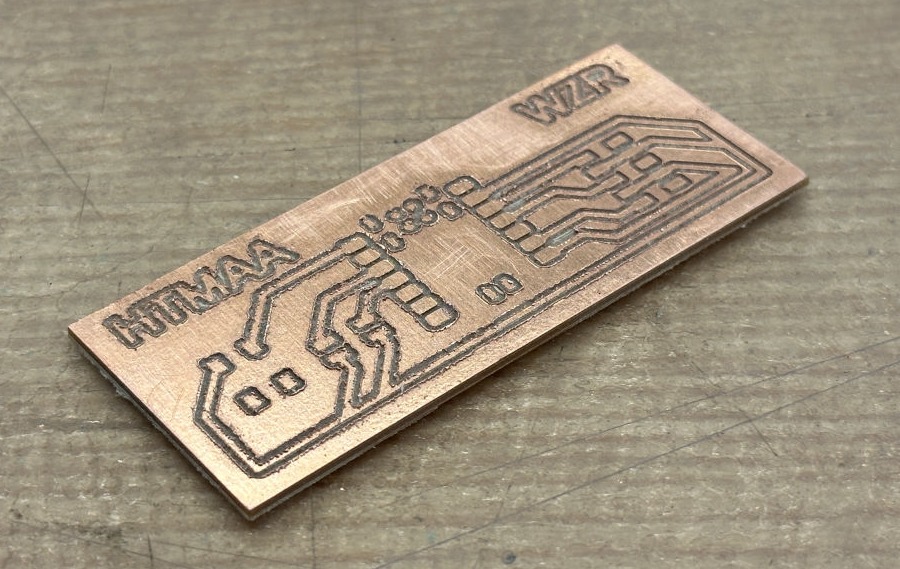
Board

The PCB is milled and only needs a bit of sand before soldering.

Mobirise Website Builder
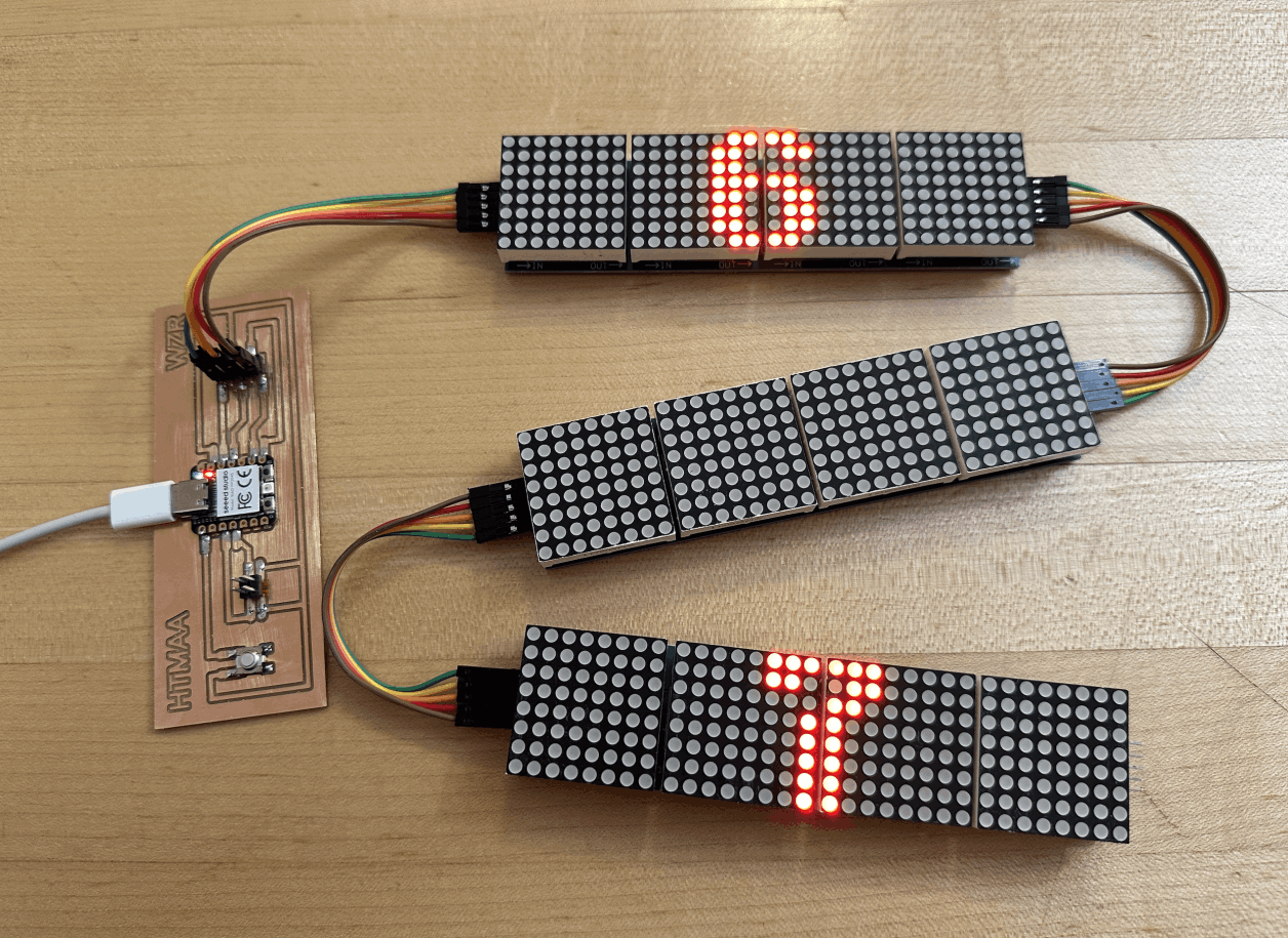
Solder and Connection

The PCB is then soldered with the RP2040, several pins, and a button. Alongside, I was plugging these LED matrixes, and powered by my Mac to test the electronic.

Interaction test: from stepping input to LED output

Code for interaction test

// Pin Definitions for RP2040
#define pin1 1 // Chip Select (CS)
#define pin2 2 // Clock (SCK)
#define pin3 3 // Data Input (MOSI)
#define buttonPin1 28 // Button Input 1
#define buttonPin2 29 // Button Input 2

// LED Matrix Setup
#define X_SEGMENTS 4 // 4 LED matrix bars horizontally
#define Y_SEGMENTS 3 // 3 rows of matrices
#define NUM_SEGMENTS (X_SEGMENTS * Y_SEGMENTS)

// Framebuffer
byte fb[8 * NUM_SEGMENTS];
uint8_t number1 = 0; // Controlled by buttonPin1
uint8_t number2 = 0; // Controlled by buttonPin2
unsigned long lastPressTime1 = 0;
unsigned long lastPressTime2 = 0;
const unsigned long debounceDelay = 2500; // 2.5 seconds

// Function to Send Data to All MAX7219s
void shiftAll(byte address, byte data) {
digitalWrite(pin1, LOW); // Enable Chip Select
for (int i = 0; i < NUM_SEGMENTS; i++) {
shiftOut(pin3, pin2, MSBFIRST, address); // Send address
shiftOut(pin3, pin2, MSBFIRST, data); // Send data
}
digitalWrite(pin1, HIGH); // Disable Chip Select
}

void setup() {
Serial.begin(115200);

// Initialize SPI pins
pinMode(pin1, OUTPUT); // CS
pinMode(pin2, OUTPUT); // Clock
pinMode(pin3, OUTPUT); // Data Input
pinMode(buttonPin1, INPUT_PULLUP); // Button input 1
pinMode(buttonPin2, INPUT_PULLUP); // Button input 2

// Initialize Each MAX7219
shiftAll(0x0F, 0x00); // Display Test Register - Test Mode OFF
shiftAll(0x0B, 0x07); // Scan Limit: Display Digits 0-7
shiftAll(0x0C, 0x01); // Shutdown Register - Normal Operation
shiftAll(0x0A, 0x08); // Brightness: Medium
shiftAll(0x09, 0x00); // Decode Mode OFF
}

void loop() {
unsigned long currentTime = millis();

if (digitalRead(buttonPin1) == LOW && (currentTime - lastPressTime1 > debounceDelay)) {
lastPressTime1 = currentTime;
if (number1 < 99) {
number1++;
Serial.print("Button 1 touched! Number 1: ");
Serial.println(number1);
}
}

if (digitalRead(buttonPin2) == LOW && (currentTime - lastPressTime2 > debounceDelay)) {
lastPressTime2 = currentTime;
if (number2 < 99) {
number2++;
Serial.print("Button 2 touched! Number 2: ");
Serial.println(number2);
}
}

// Clear framebuffer
clear();

// Draw numbers on respective rows
draw_number(12, 0, number1); // Top row for number1
draw_number(12, 16, number2); // Bottom row for number2

// Show updated framebuffer
show();
}

void set_pixel(uint8_t x, uint8_t y, uint8_t mode) {
if (x >= X_SEGMENTS * 8 || y >= Y_SEGMENTS * 8) return;
byte *addr = &fb[(y * X_SEGMENTS) + (x / 8)];
byte mask = 128 >> (x % 8);
switch (mode) {
case 0: *addr &= ~mask; break; // Clear pixel
case 1: *addr |= mask; break; // Set pixel
case 2: *addr ^= mask; break; // Toggle pixel
}
}

void clear() {
memset(fb, 0, sizeof(fb));
}

void draw_number(uint8_t x, uint8_t y, uint8_t number) {
static const byte numbers[10][8] = {
{0b00111100, 0b01100110, 0b01101110, 0b01110110, 0b01111010, 0b01110010, 0b01100110, 0b00111100}, // 0
{0b00111100, 0b00111000, 0b00011000, 0b00011000, 0b00011000, 0b00011000, 0b00111000, 0b00111100}, // 1
{0b00111100, 0b01100110, 0b01100010, 0b00000110, 0b00001100, 0b00011000, 0b01100110, 0b00111100}, // Corrected 2
{0b00111100, 0b01100110, 0b00000110, 0b00011100, 0b00000110, 0b00000110, 0b01100110, 0b00111100}, // 3
{0b00001100, 0b00011100, 0b00101100, 0b01001100, 0b01111110, 0b00001100, 0b00001100, 0b00001100}, // 4
{0b01111110, 0b01100000, 0b01111100, 0b00000110, 0b00000110, 0b00000110, 0b01100110, 0b00111100}, // 5
{0b00111100, 0b01100110, 0b01100000, 0b01111100, 0b01100110, 0b01100110, 0b01100110, 0b00111100}, // 6
{0b01111110, 0b01100110, 0b00001100, 0b00011000, 0b00011000, 0b00011000, 0b00011000, 0b00011000}, // 7
{0b00111100, 0b01100110, 0b01100110, 0b00111100, 0b01100110, 0b01100110, 0b01100110, 0b00111100}, // 8
{0b00111100, 0b01100110, 0b01100110, 0b00111110, 0b00000110, 0b00000110, 0b01100110, 0b00111100} // 9
};

for (byte row = 0; row < 8; row++) {
for (byte col = 0; col < 8; col++) {
if (numbers[number][row] & (1 << col)) {
set_pixel(x + col, y + row, 1);
}
}
}
}

void show() {
for (byte row = 0; row < 8; row++) {
digitalWrite(pin1, LOW);
for (byte segment = 0; segment < NUM_SEGMENTS; segment++) {
byte x = segment % X_SEGMENTS;
byte y = segment / X_SEGMENTS * 8;
byte addr = (row + y) * X_SEGMENTS;
shiftOut(pin3, pin2, MSBFIRST, 8 - row);
shiftOut(pin3, pin2, MSBFIRST, fb[addr + x]);
}
digitalWrite(pin1, HIGH);
}
}
System Integration

Architecture to house the scoring system
Mobirise Website Builder
3D Design

Tried out several iterations for the final architecture design in Rhino.

Mobirise Website Builder
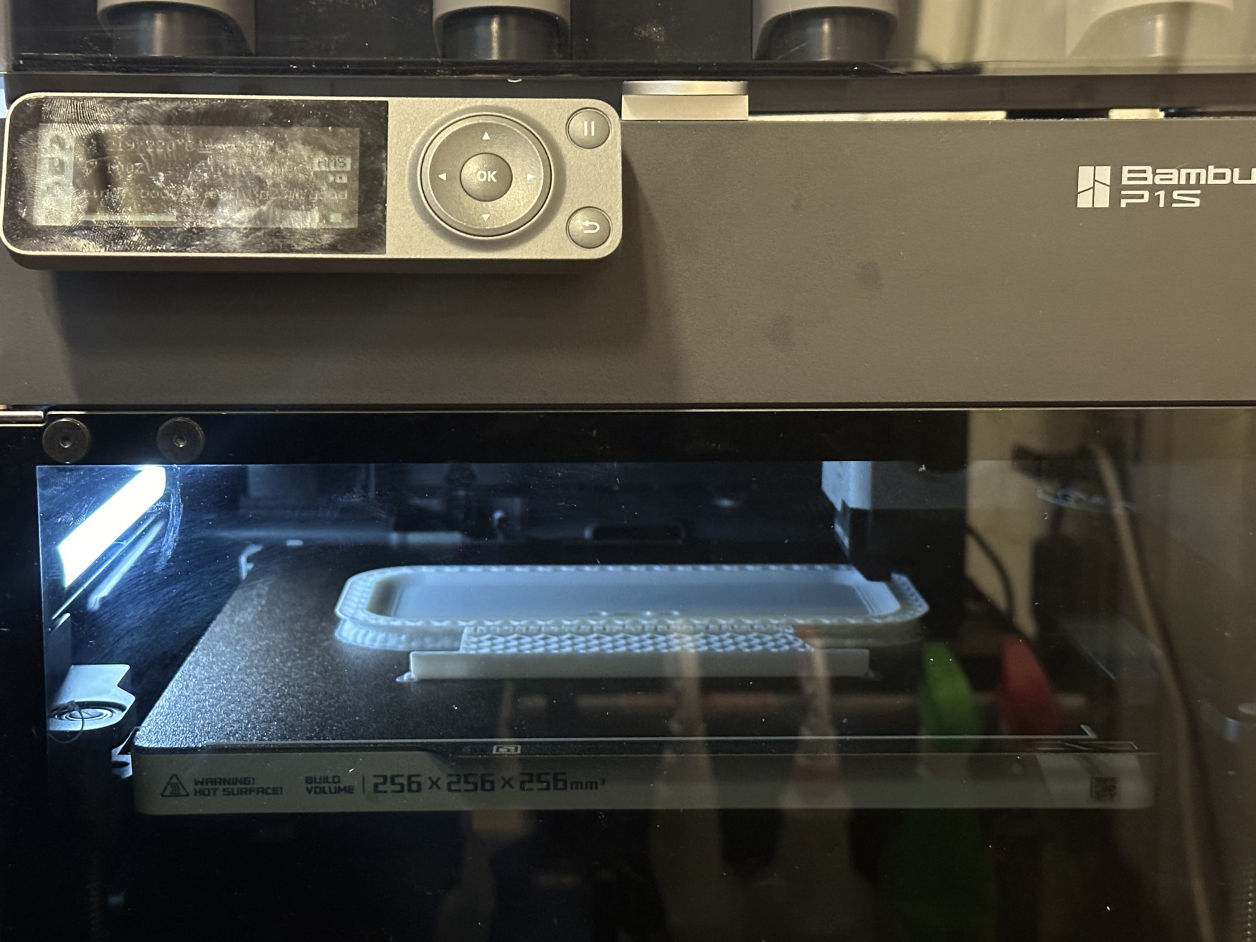
3D Print

Mobirise Website Builder
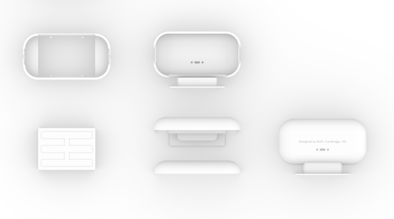
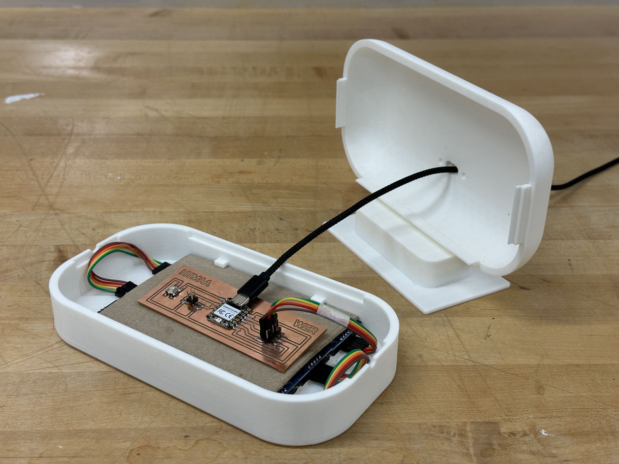
Container

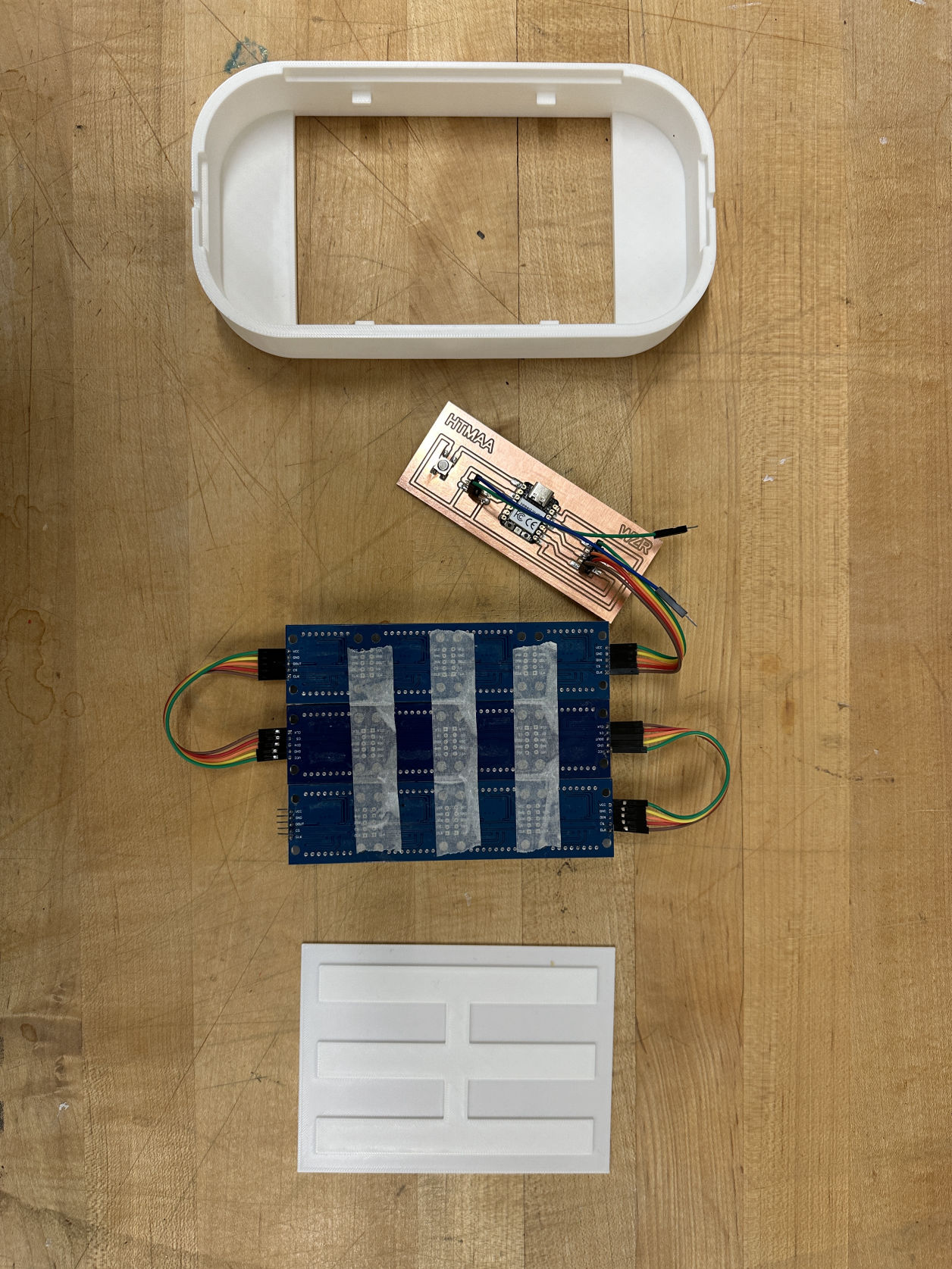
The structure has to contain one PCB and three LED matrixes, leaving enough space for the wiring.

Mobirise Website Builder
Electro bento box

The design kind of reminds me a Japanese bento box. And my goal is trying to make this both compact and aesthetically nice!

Mobirise Website Builder
Press & Fit

Instead of using screws, the enclosure of this body was designed for an easy press-fit joint. I personally enjoy the moment of clicking it!

Mobirise Website Builder
Connectors

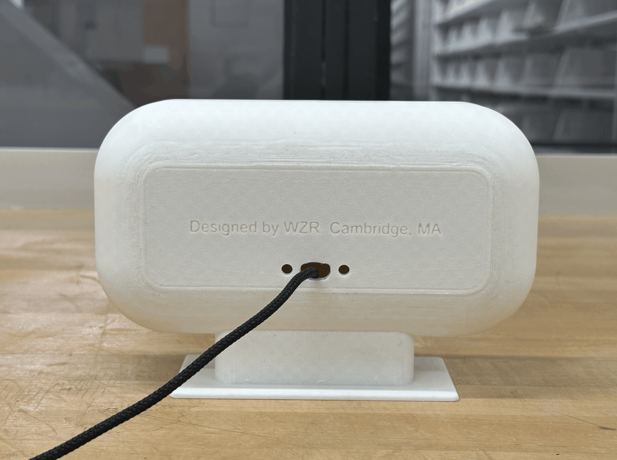
The back the house has three openings: one for the main power and overwrite (USB-C), while the other two are for the wires from the end of factor sensors on the pinball table.

Designed by WZR. Cambridge, MA.

Mobirise Website Builder
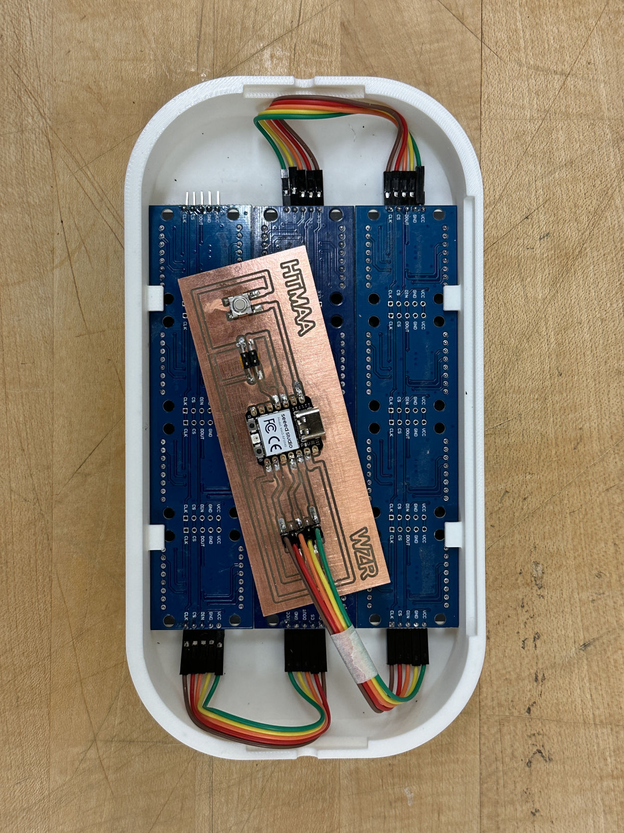
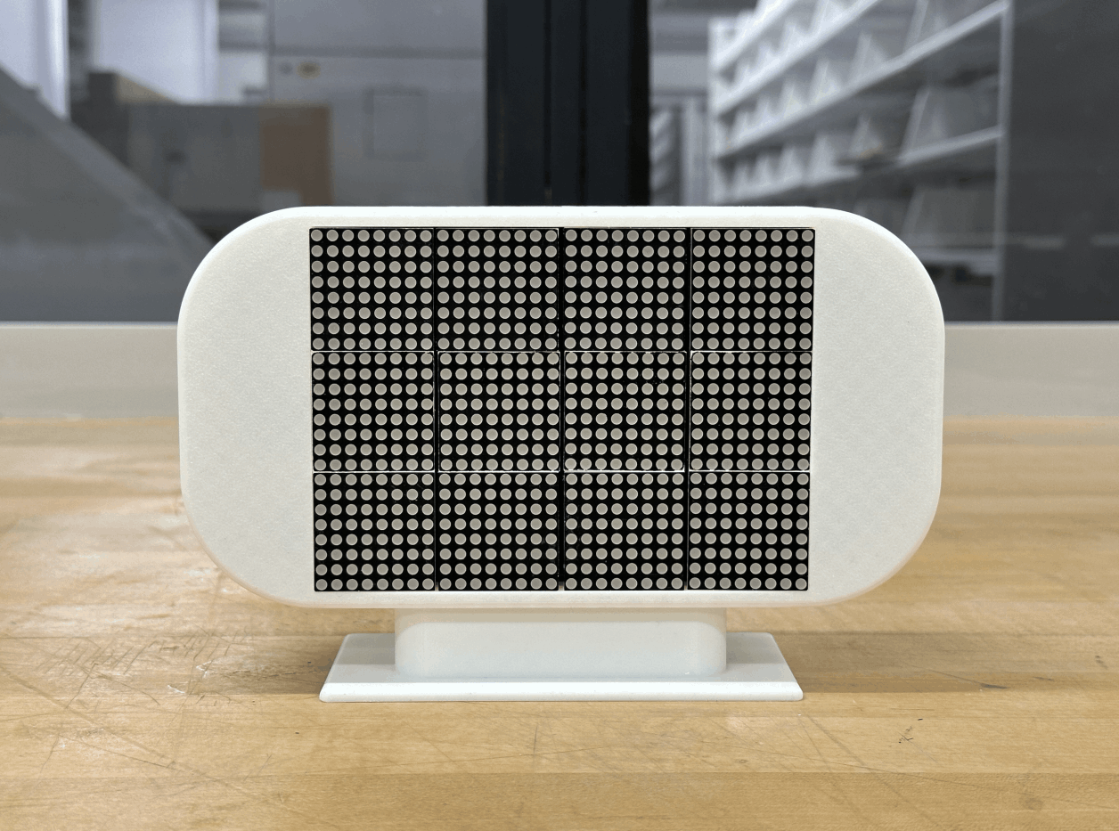
LED Matrix

Surprisingly, the matrixes fit pretty well in my shell. It ended up coming together without any glue or tape, since the dimension was quite accurate.

Scoring board architecture

Final code for animations and interaction scoring 

// Pin Definitions for RP2040
#define pin1 1 // Chip Select (CS)
#define pin2 2 // Clock (SCK)
#define pin3 3 // Data Input (MOSI)
#define buttonPin1 28 // Button Input 1
#define buttonPin2 29 // Button Input 2

// LED Matrix Setup
#define X_SEGMENTS 4 // 4 LED matrix bars horizontally
#define Y_SEGMENTS 3 // 3 rows of matrices
#define NUM_SEGMENTS (X_SEGMENTS * Y_SEGMENTS)

// Framebuffer
byte fb[8 * NUM_SEGMENTS];

// Game Variables
uint8_t number1 = 0; // Controlled by buttonPin1
uint8_t number2 = 0; // Controlled by buttonPin2
unsigned long lastPressTime1 = 0;
unsigned long lastPressTime2 = 0;
const unsigned long debounceDelay = 2500; // 2.5 seconds

// Fire Animation Variables
#define FIRE_WIDTH 8
int fire_offset = 0; // Offset for X-axis fire animation
unsigned long lastFireUpdate = 0;
const unsigned long flameUpdateInterval = 50; // Fire refresh every 0.3 seconds

// Custom Image Patterns (HTMAA Layout)
const uint8_t IMAGES[][8] = {
{
0b00000000,
0b01000100,
0b01000100,
0b01111100,
0b01111100,
0b01000100,
0b01000101,
0b00000000
},{
0b00000000,
0b01000100,
0b01000101,
0b01000111,
0b01000110,
0b01000110,
0b11110100,
0b00000000
},{
0b00000000,
0b01010001,
0b01010001,
0b11011111,
0b11010001,
0b11001010,
0b01000100,
0b00000000
},{
0b00000000,
0b01000100,
0b01000100,
0b01111100,
0b01000100,
0b00101000,
0b00010000,
0b00000000
}};
const int IMAGES_LEN = sizeof(IMAGES) / 8;

// Function to Send Data to All MAX7219s
void shiftAll(byte address, byte data) {
digitalWrite(pin1, LOW); // Enable Chip Select
for (int i = 0; i < NUM_SEGMENTS; i++) {
shiftOut(pin3, pin2, MSBFIRST, address); // Send address
shiftOut(pin3, pin2, MSBFIRST, data); // Send data
}
digitalWrite(pin1, HIGH); // Disable Chip Select
}

// Display Custom Images Across All Three Rows with Middle Row Flipped
void flashCustomImages() {
for (int flash = 0; flash < 7; flash++) { // Repeat the sequence 3 times
for (int img = 0; img < IMAGES_LEN; img++) {
clear();
for (byte row = 0; row < 8; row++) {
for (byte col = 0; col < 8; col++) {
if (IMAGES[img][row] & (1 << (7 - col))) {
// First matrix row (Y1-8)
set_pixel(col + (img % X_SEGMENTS) * 8, row, 1);

// Middle matrix row flipped (Y9-16)
set_pixel(7 - col + (img % X_SEGMENTS) * 8, 15 - row, 1);

// Third matrix row (Y17-24)
set_pixel(col + (img % X_SEGMENTS) * 8, row + 16, 1);
}
}
}
show();
delay(200); // 3-second display per image
}
}
}

void setup() {
// Initialize SPI pins
pinMode(pin1, OUTPUT); // CS
pinMode(pin2, OUTPUT); // Clock
pinMode(pin3, OUTPUT); // Data Input
pinMode(buttonPin1, INPUT_PULLUP); // Button input 1
pinMode(buttonPin2, INPUT_PULLUP); // Button input 2

// Initialize Each MAX7219
shiftAll(0x0F, 0x00); // Test Mode OFF
shiftAll(0x0B, 0x07); // Scan Limit: Digits 0-7
shiftAll(0x0C, 0x01); // Normal Operation
shiftAll(0x0A, 0x04); // Reduced Brightness
shiftAll(0x09, 0x00); // Decode Mode OFF

// Flash custom images
flashCustomImages();
}

void loop() {
unsigned long currentTime = millis();

// Handle Button Press for Increment
if (digitalRead(buttonPin1) == LOW && (currentTime - lastPressTime1 > debounceDelay)) {
lastPressTime1 = currentTime;
if (number1 < 99) number1++;
}

if (digitalRead(buttonPin2) == LOW && (currentTime - lastPressTime2 > debounceDelay)) {
lastPressTime2 = currentTime;
if (number2 < 99) number2++;
}

// Update Flame Every 0.3 Seconds
if (currentTime - lastFireUpdate >= flameUpdateInterval) {
lastFireUpdate = currentTime;
clear();
draw_fire_background();
draw_number(12, 0, number1); // Top row for number1
draw_number(12, 16, number2); // Bottom row for number2
show();
}
}

// Set Pixel in Framebuffer
void set_pixel(uint8_t x, uint8_t y, uint8_t mode) {
if (x >= X_SEGMENTS * 8 || y >= Y_SEGMENTS * 8) return;
byte *addr = &fb[(y * X_SEGMENTS) + (x / 8)];
byte mask = 128 >> (x % 8);
if (mode) *addr |= mask; // Set pixel
else *addr &= ~mask; // Clear pixel
}

// Clear the Framebuffer
void clear() {
memset(fb, 0, sizeof(fb));
}

// Fire Animation (Less Dense)
void draw_fire_background() {
fire_offset = (fire_offset + 1) % FIRE_WIDTH; // Shift fire sideways

for (uint8_t row = 0; row < 24; row++) {
uint8_t height = random(1, 8); // Reduced flame height
if (random(0, 100) < 75) { // Lower chance for flame appearance
for (uint8_t col = 0; col < height; col++) {
set_pixel((col + fire_offset) % FIRE_WIDTH, row, 1); // Left side
set_pixel(31 - ((col + fire_offset) % FIRE_WIDTH), row, 1); // Right side
}
}
}
}

// Draw Numbers
void draw_number(uint8_t x, uint8_t y, uint8_t number) {
static const byte numbers[10][8] = {

{
0b00111100,
0b01100110,
0b01100110,
0b01111010,
0b01110010,
0b01100110,
0b01100110,
0b00111100}, // 0

{
0b00011000,
0b00011000,
0b00011000,
0b00011000,
0b00011000,
0b00011000,
0b00011110,
0b00011000}, // 1

{
0b01111110,
0b00000110,
0b00011000,
0b00110000,
0b01100000,
0b01000010,
0b01100110,
0b00111100}, // 2

{
0b00111100,
0b01100110,
0b01100000,
0b00110000,
0b00011100,
0b01100000,
0b01100110,
0b00111100}, // 3

{
0b00110000,
0b00110000,
0b00110000,
0b01111110,
0b00100110,
0b00110100,
0b00111000,
0b00110000}, // 4

{
0b00111110,
0b01100000,
0b01100000,
0b01100000,
0b00111110,
0b00000110,
0b00000110,
0b00111110}, // 5

{
0b00111100,
0b01100110,
0b01100110,
0b01100110,
0b00111110,
0b00000110,
0b01100110,
0b00111100}, // 6

{
0b00001100,
0b00001100,
0b00001100,
0b00001100,
0b00011000,
0b00110000,
0b01100000,
0b01111110}, // 7

{
0b00111100,
0b01100110,
0b01100110,
0b01100110,
0b00111100,
0b01100110,
0b01100110,
0b00111100}, // 8

{
0b00111100,
0b01100100,
0b01100000,
0b01100000,
0b01111110,
0b01100110,
0b01100110,
0b00111100} // 9
};

for (byte row = 0; row < 8; row++) {
for (byte col = 0; col < 8; col++) {
if (numbers[number][row] & (1 << col)) {
set_pixel(x + col, y + row, 1);
}
}
}
}


// Show Framebuffer
void show() {
for (byte row = 0; row < 8; row++) {
digitalWrite(pin1, LOW);
for (byte segment = 0; segment < NUM_SEGMENTS; segment++) {
byte x = segment % X_SEGMENTS;
byte y = segment / X_SEGMENTS * 8;
byte addr = (row + y) * X_SEGMENTS;
shiftOut(pin3, pin2, MSBFIRST, 8 - row);
shiftOut(pin3, pin2, MSBFIRST, fb[addr + x]);
}
digitalWrite(pin1, HIGH);
}
}
Fab Light laser cutting

End of Factor Design

Mobirise Website Builder
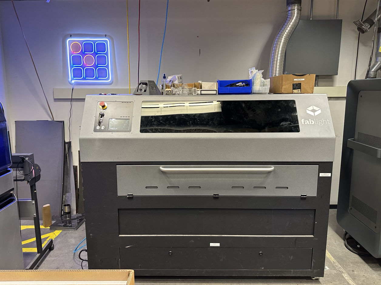
Fab Light Laser Cutter
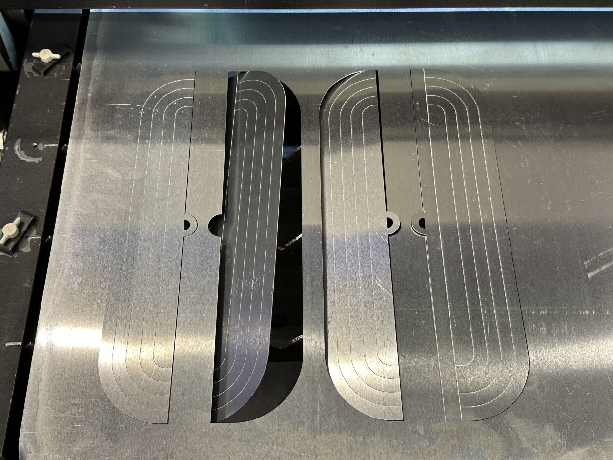
For the final project's end of factors, I need two pairs of iron plates that can transfer the data. Thus, I went to CBA's lab to run a laser cutting and scoring on Aluminum sheets. 


Mobirise Website Builder
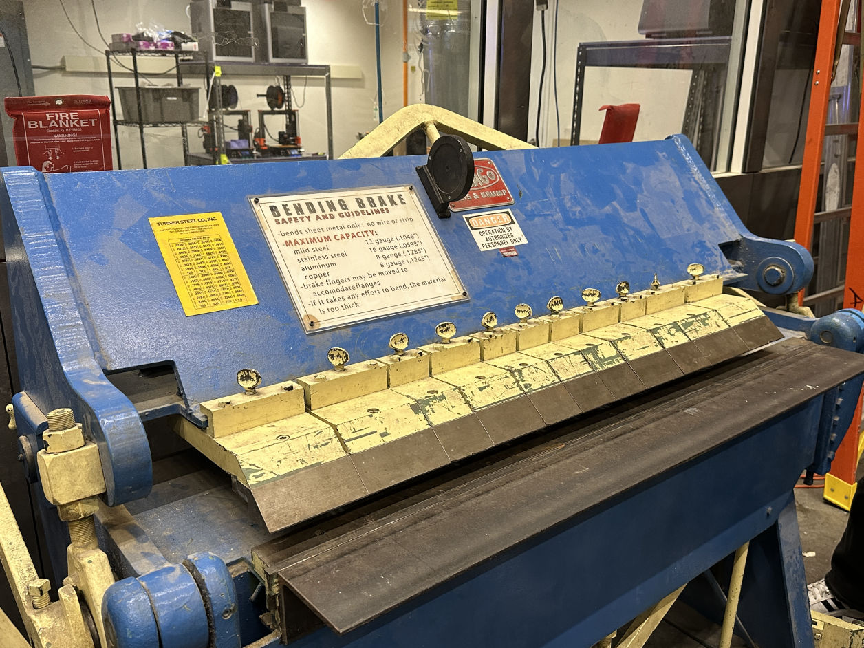
Bending Brake

Mobirise Website Builder
Materials

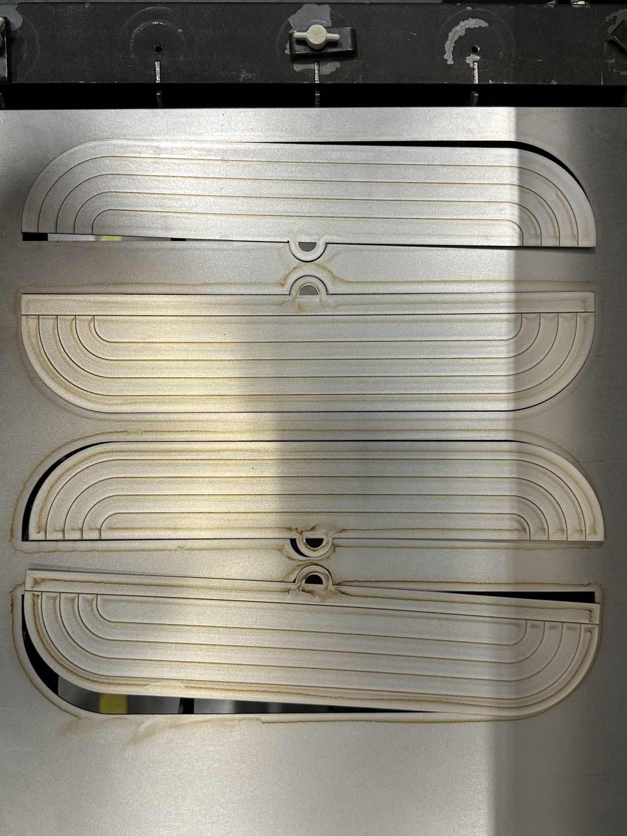
I was trying to cut both aluminum and metal to see which works better in terms of its weight and finishes.

Mobirise Website Builder
File Preparation

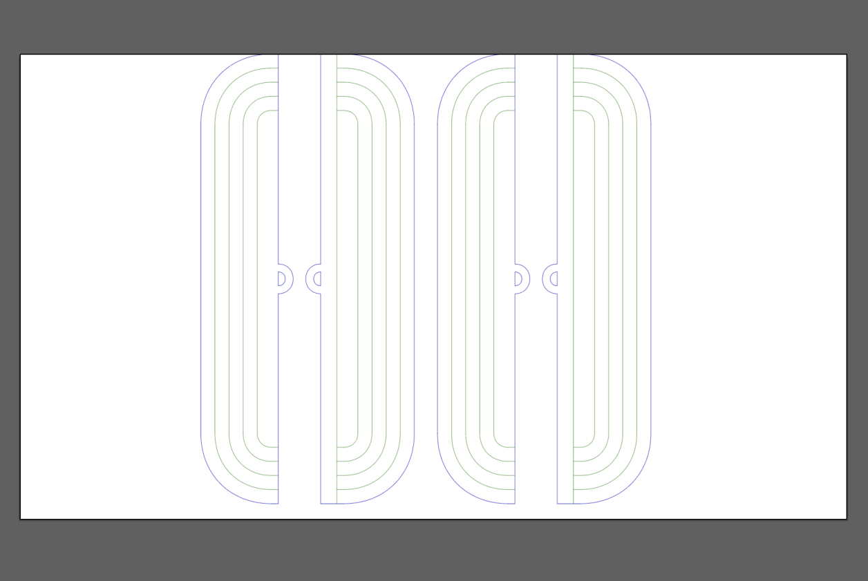
The file was prepared with two layers only, one for cutting and one for scoring.

Mobirise Website Builder
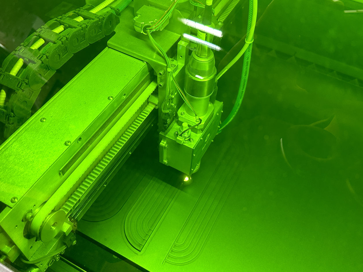
Starting the Job

Mobirise Website Builder
Material A: Aluminum

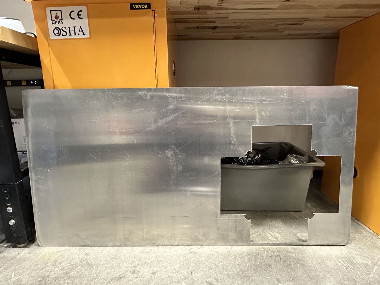
The aluminum laser cut was getting a great result with a clean cut and nice scoring!

Mobirise Website Builder
Material B: Metal

The metal laser cut is a bit rougher and needed more work on processing it afterwards.

Mobirise Website Builder
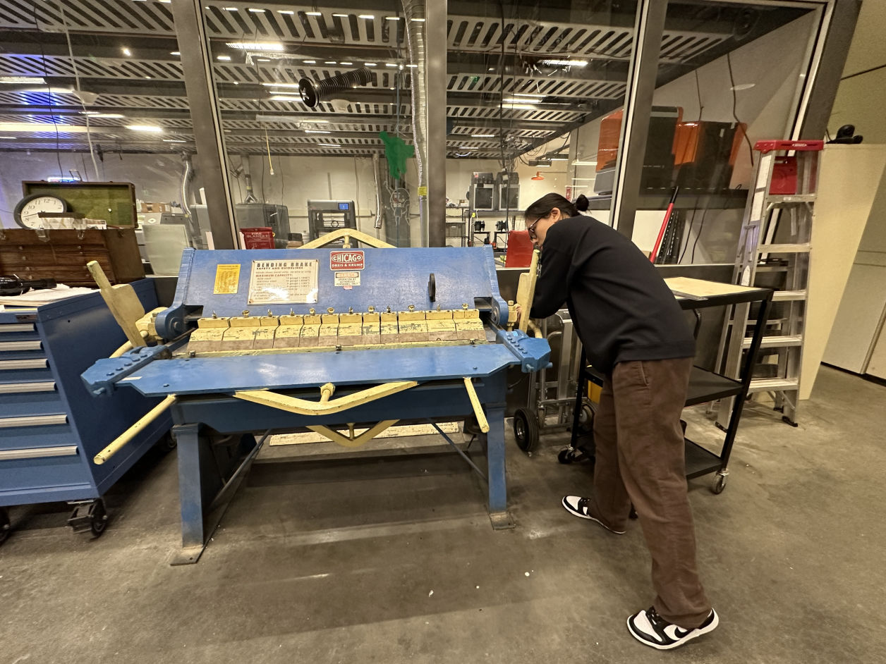
Bending

The metal laser cut is a bit rougher and needed more work on processing it afterwards.

Mobirise Website Builder
Result

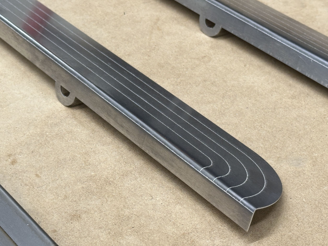
I am quite happy with the final result of the aluminum parts, both its finishes and the bending curve.

Mobirise Website Builder
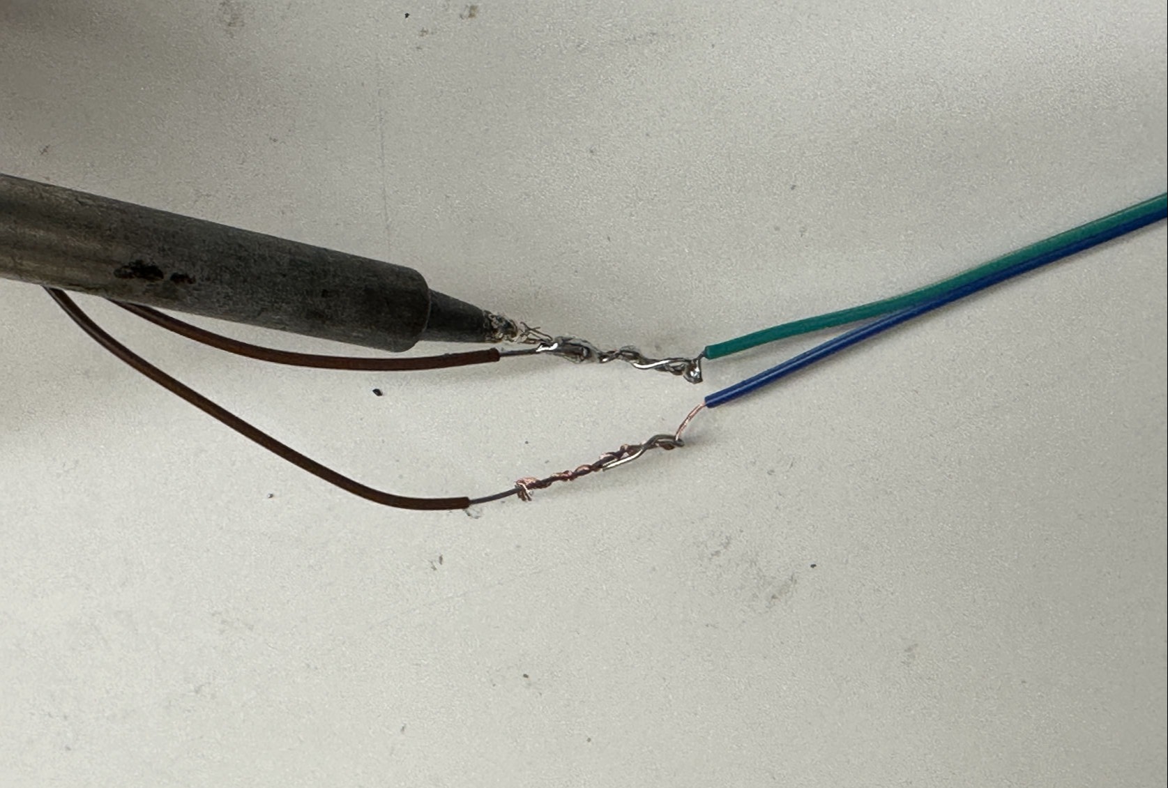
Wiring

I used the splicing wires method with NASA standard to make the wire attached to the plates stabily.

Mobirise Website Builder
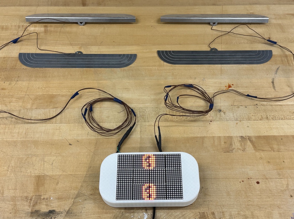
Connecting

The wires could be clearly connected from the plates to the main board from two sides as shown in the photo. 

Mobirise Website Builder
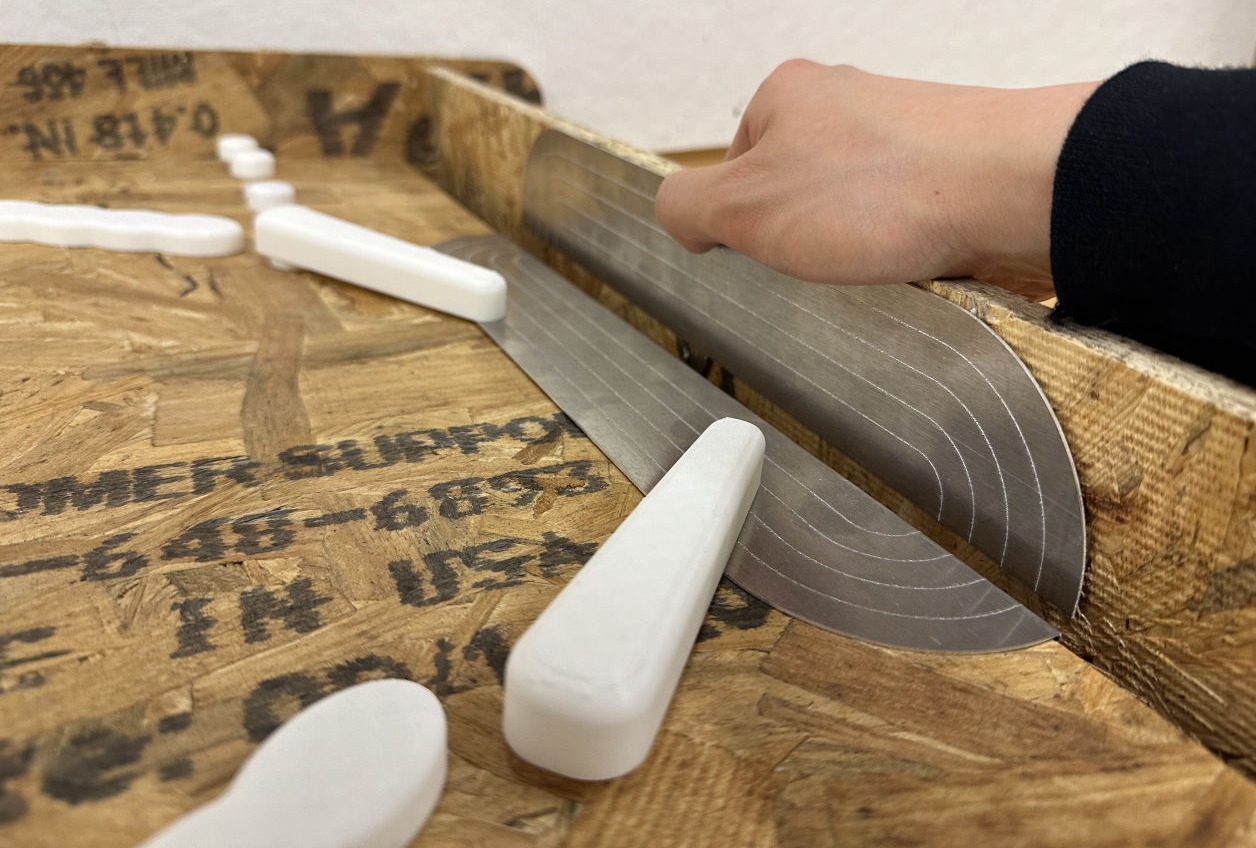
Finishing

The plates are then attached to the surface of a pinball machine. There is a gap between the two surfaces in order to keep it unconnected. Once the pinball hits the corner, it will ground the loop and send the signal back to the main board.

Mobirise Website Builder
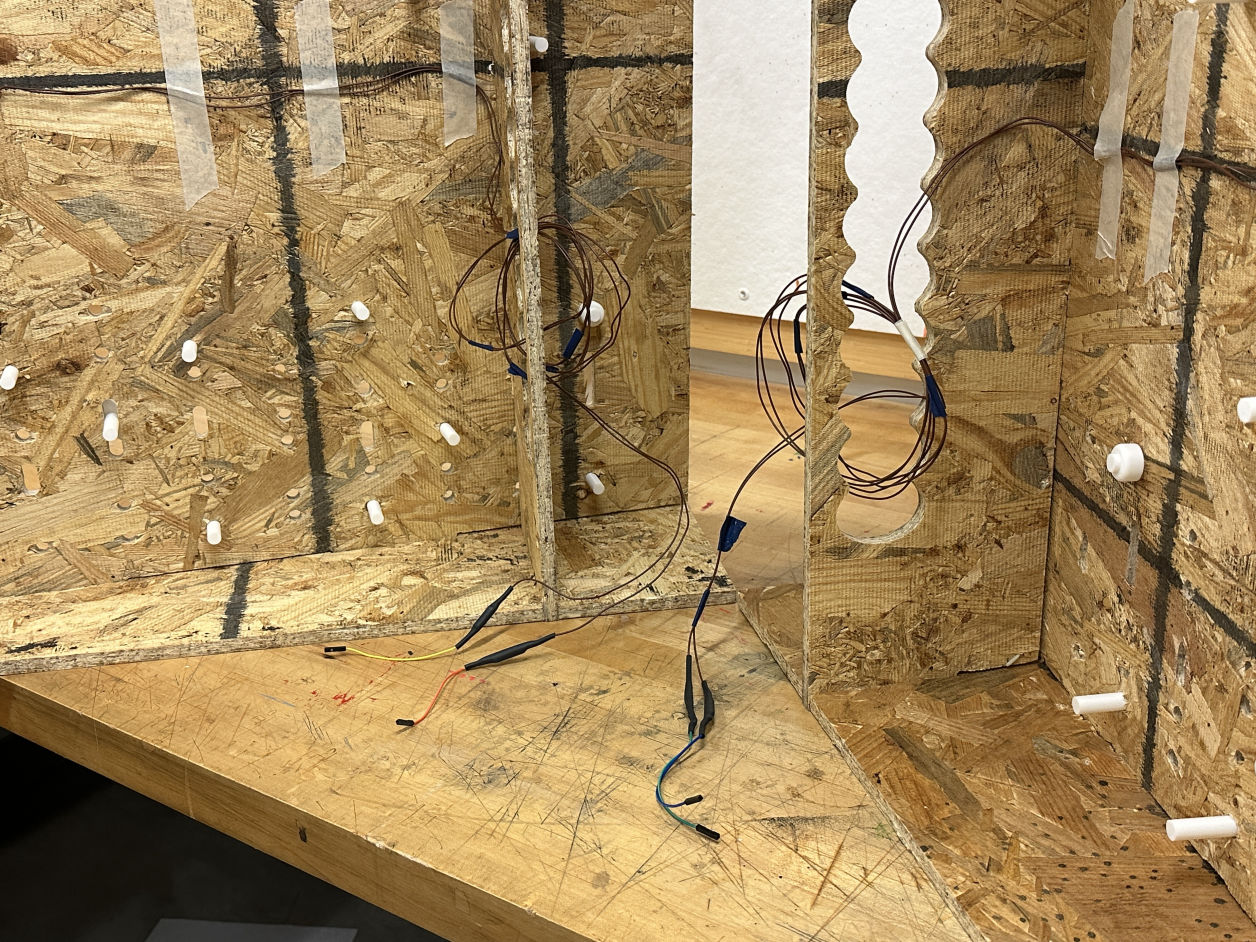
Back of house

There are holes in between the structures underneath the surface. These spaces were originally designed for wires to run through.

Mobirise Website Builder

Testing the bridge with a pinball

How to wrap almost anything?

Mobirise Website Builder
: )
It was one day before the final presentation, and my Amazon order had not arrived yet. I struggled to find the pinball since it played the most crucial character as a conductor of my final project.

I ended up try to make my own pinball!!!


Mobirise Website Builder
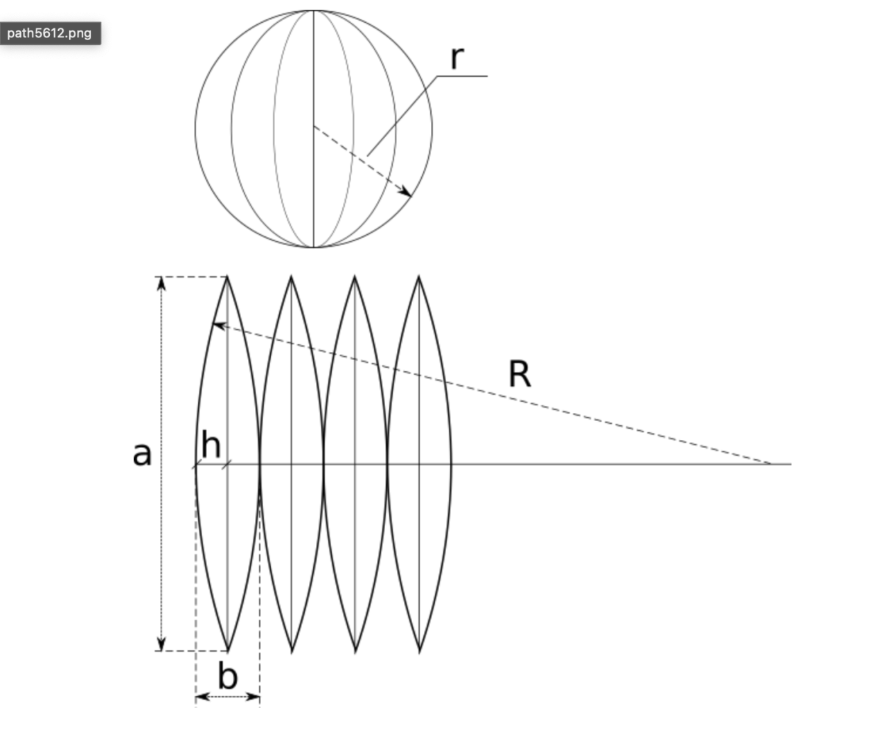
Math

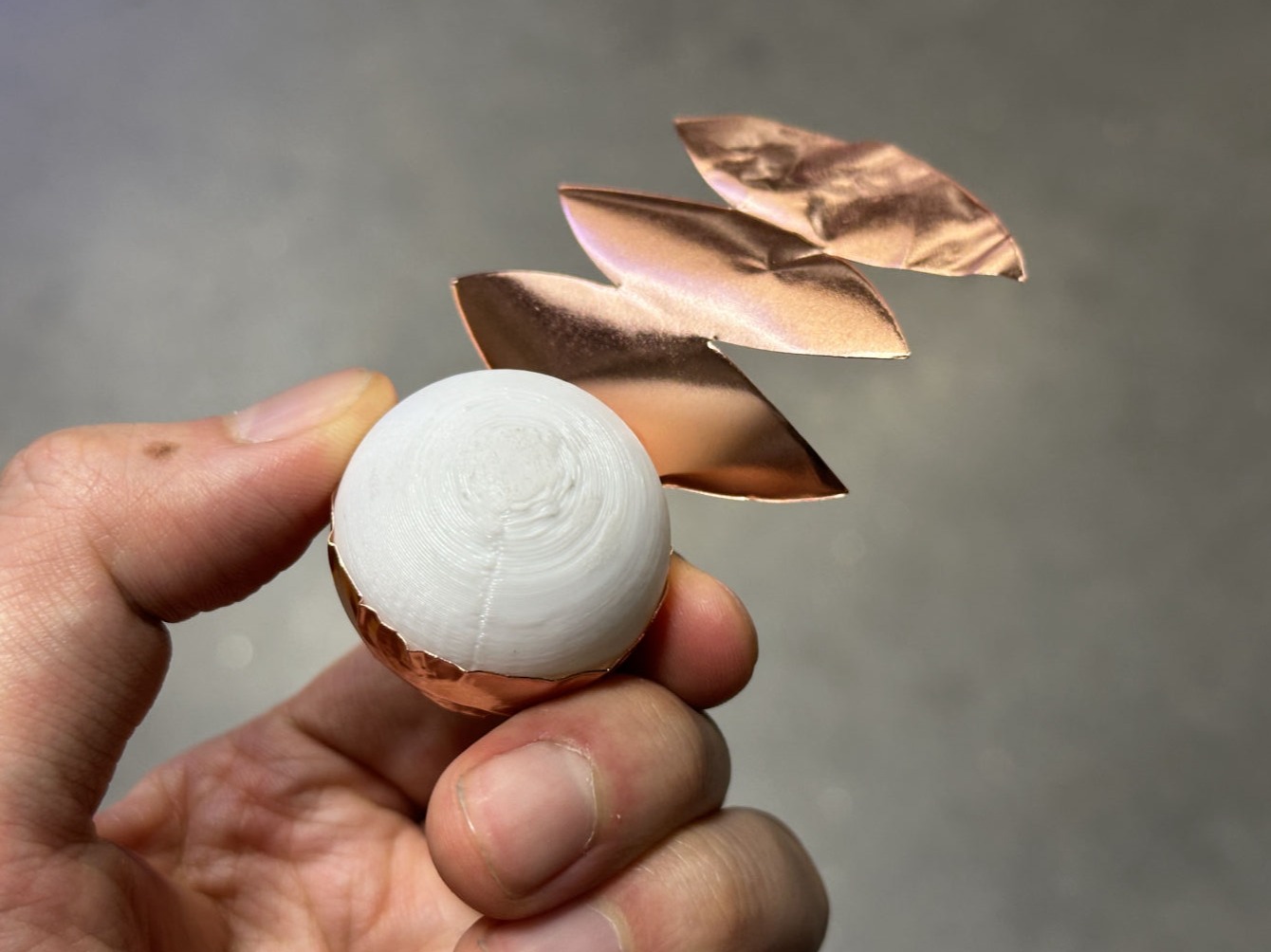
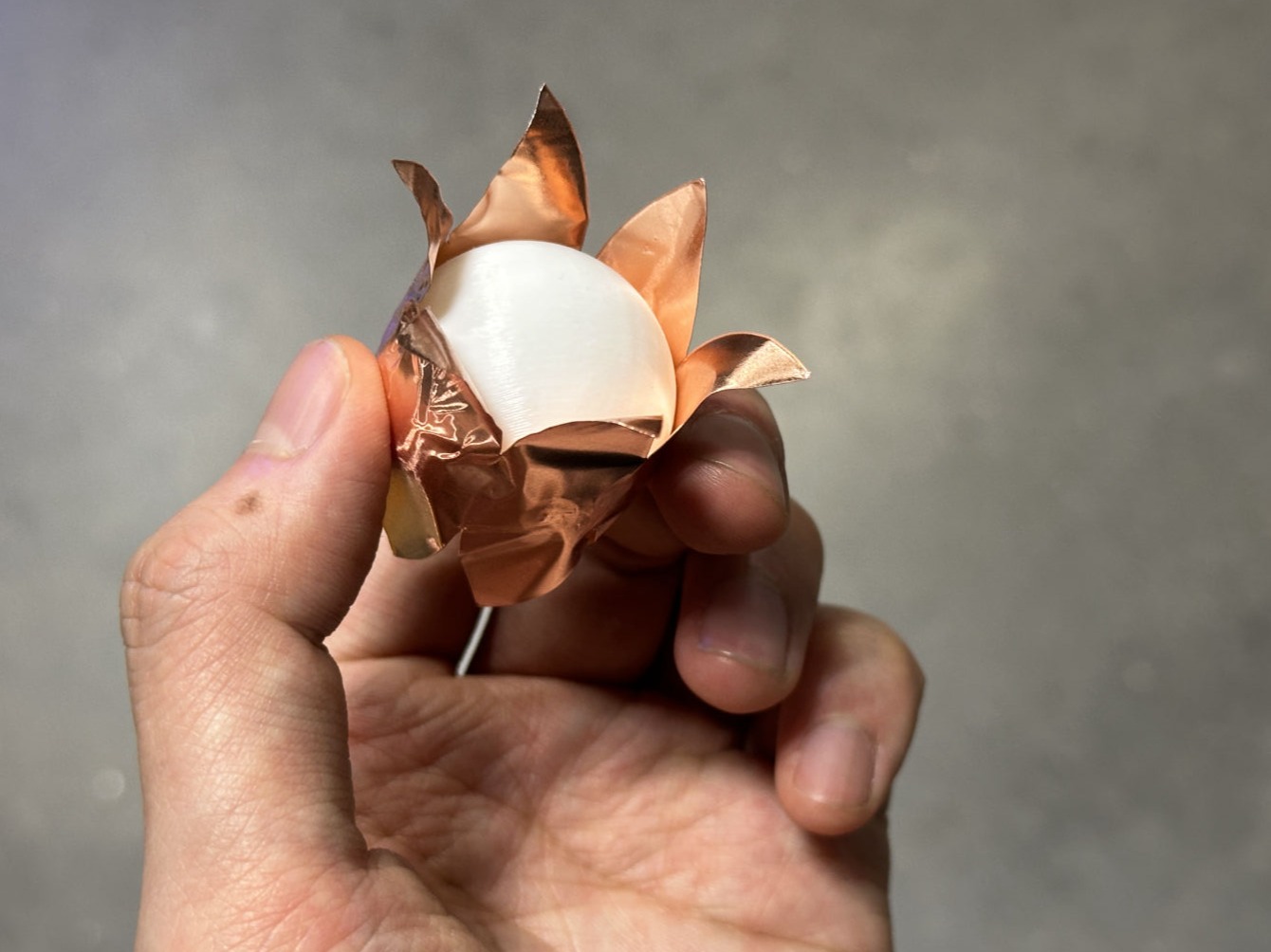
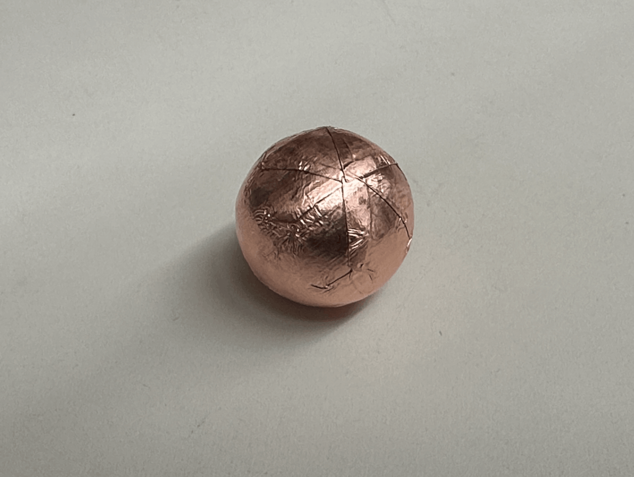
Thanks to Alan, we came up with a genius way to print a PLA ball, and wrap it with the copper sheet. This is a diagram showing how we can unwrap the geometry and make a flattened file to vinyl cut.

Mobirise Website Builder
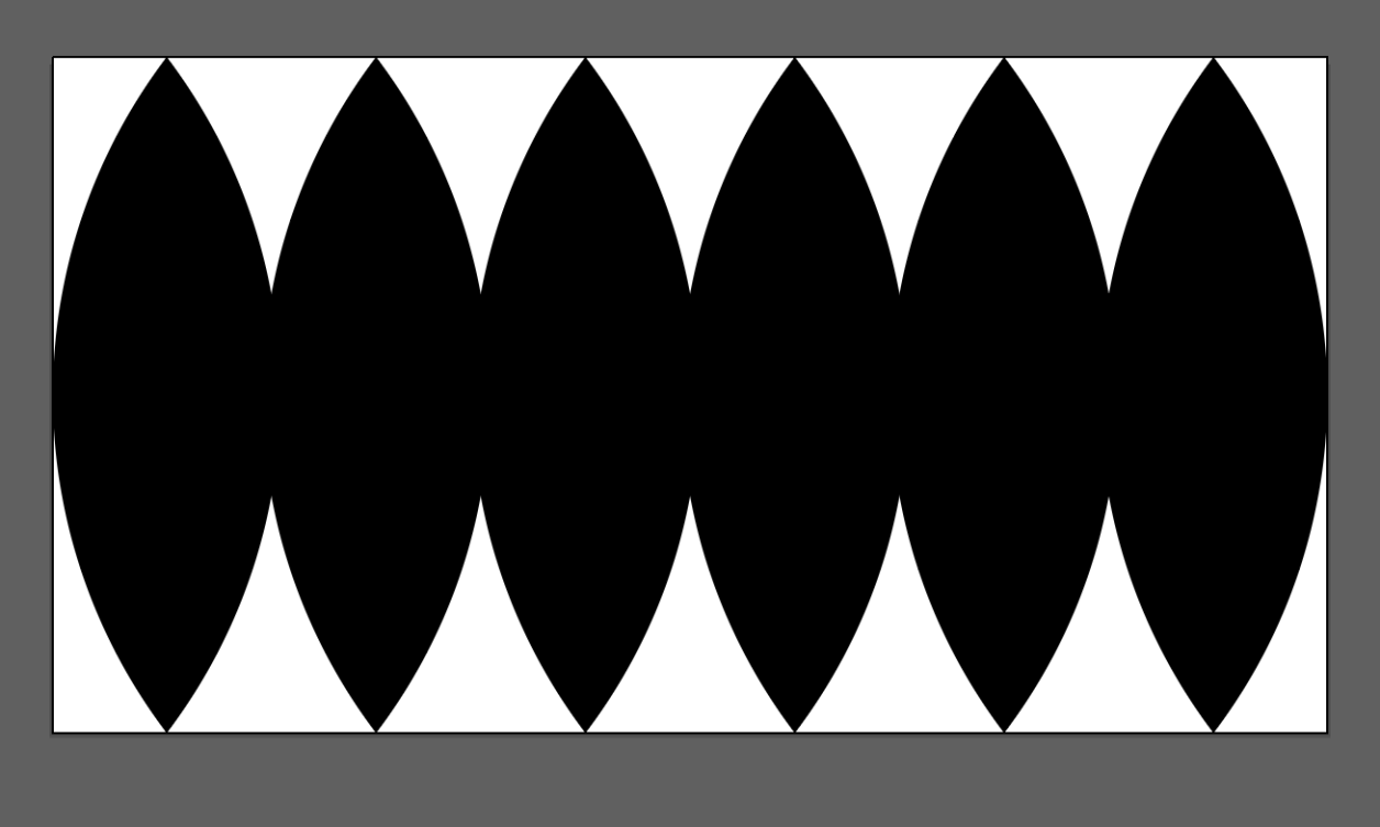
Unroll the surface of a pinball 

This is the flattened surface for a standard pinball's coating.

Mobirise Website Builder
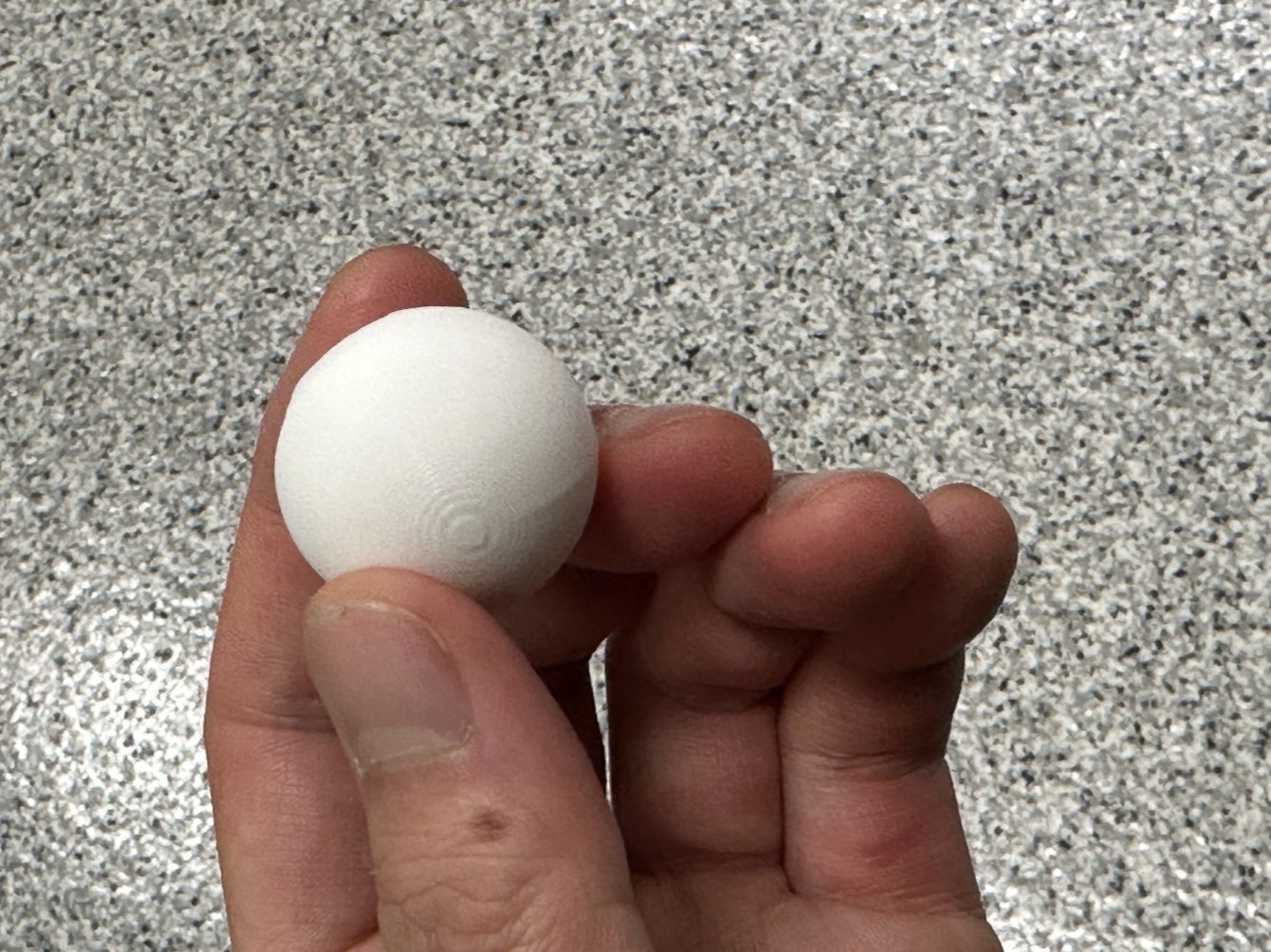
3D Print

The ball was printed with Bambu

Mobirise Website Builder
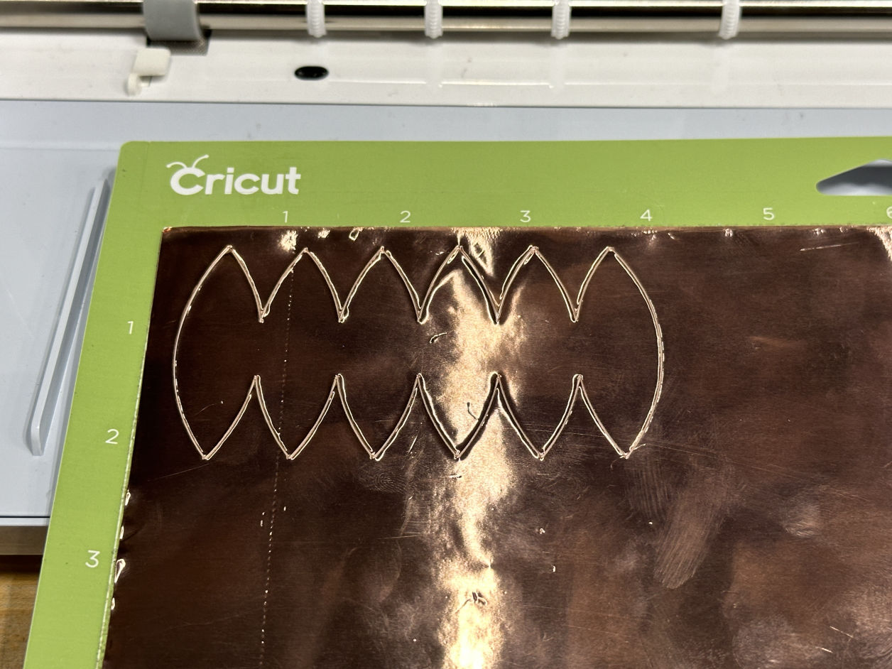
Vinyl Cut

Cutting off the copper sheet.

Mobirise Website Builder
Wrap

Mobirise Website Builder

Mobirise Website Builder
Smash!

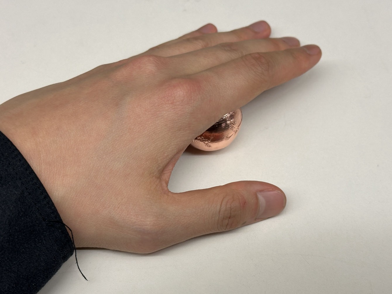
Smash it on the table carefully.

Mobirise Website Builder
Result

Here is the copper-coated pinball!

Mobirise Website Builder
Electrolysis Tank

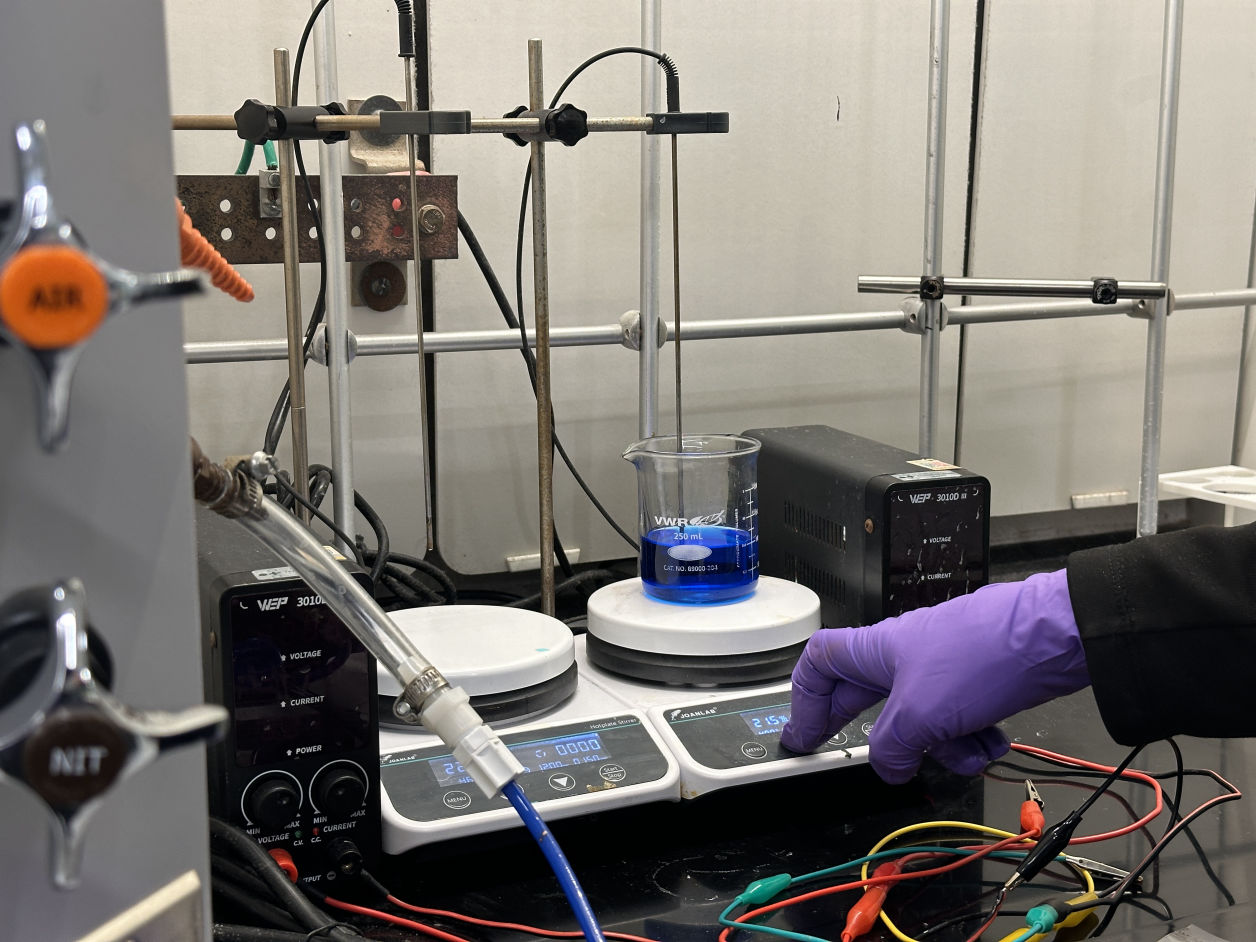
Fun fact that I also tried to electrify the PLA to make the iron attached on its surface, but the result wasn't that good.

Mobirise Website Builder
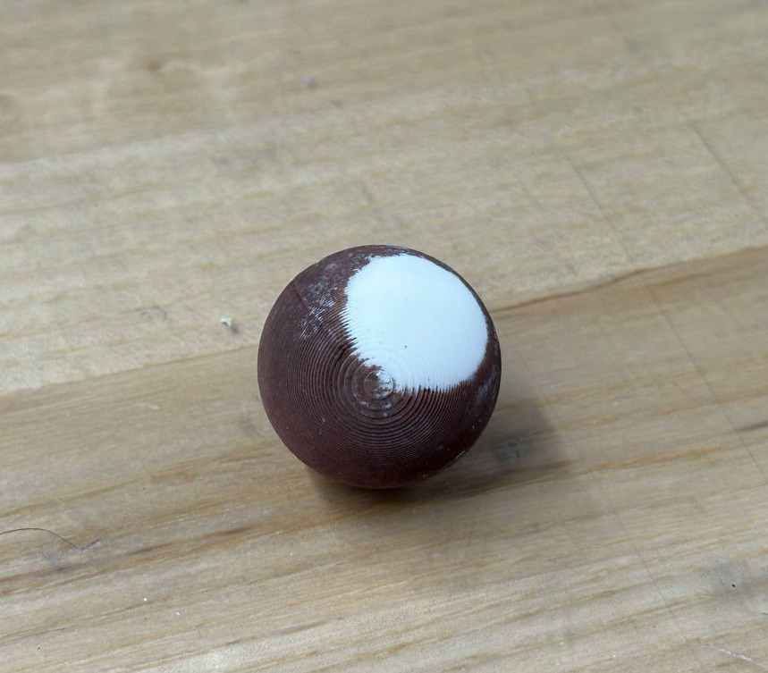
Bald Ball?

The PLA ball was attached to copper after being electrified.  However, because the infill was not dense enough, the ball floated on the surface during the process and caused this funny bald coating.

Final Results

Mobirise Website Builder

Mobirise Website Builder

Mobirise Website Builder

Mobirise Website Builder

2nd-Generation: Playing pinball machine with Neil

4 : 2

After Life

Mobirise Website Builder
What's next?

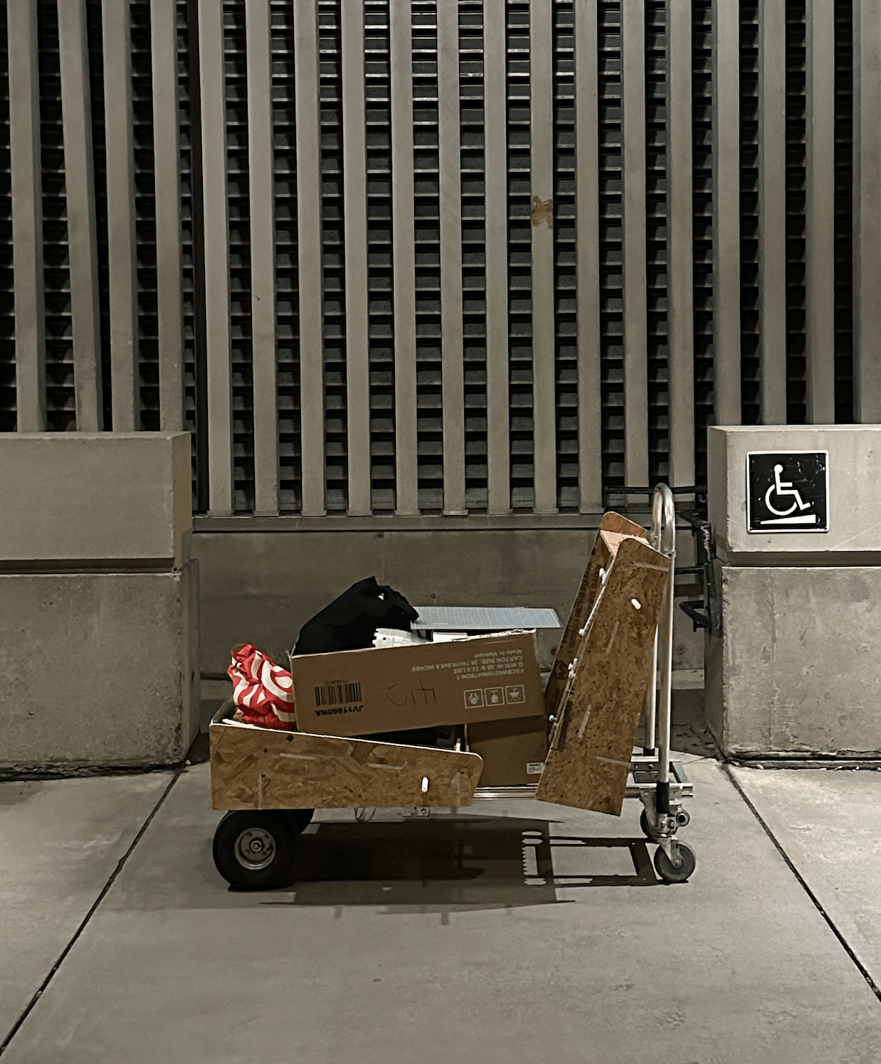
I found this image quite interesting. It correctly reflects the state of my body and mind after crippling for a semester.

After the presentation, I was wondering where I should put this? And how can I really make people engage with my machine?

Mobirise Website Builder
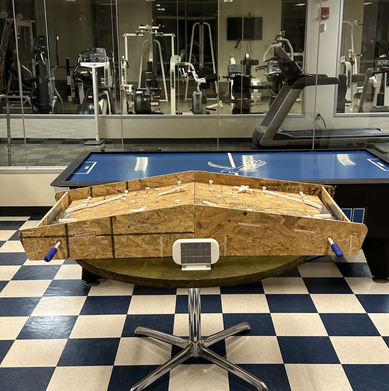
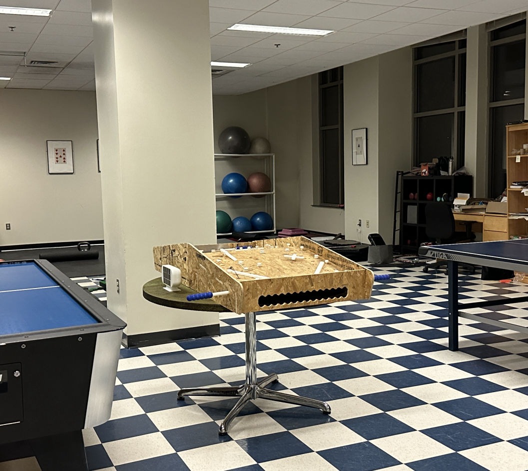
Arcade in the dormitory!

I ended up placing it in the public space of our student housing. Currently some functions are yet to be fixed to make people more engaged, but we will see.

To be continued...

Mobirise Website Builder

Project Index

Mobirise