
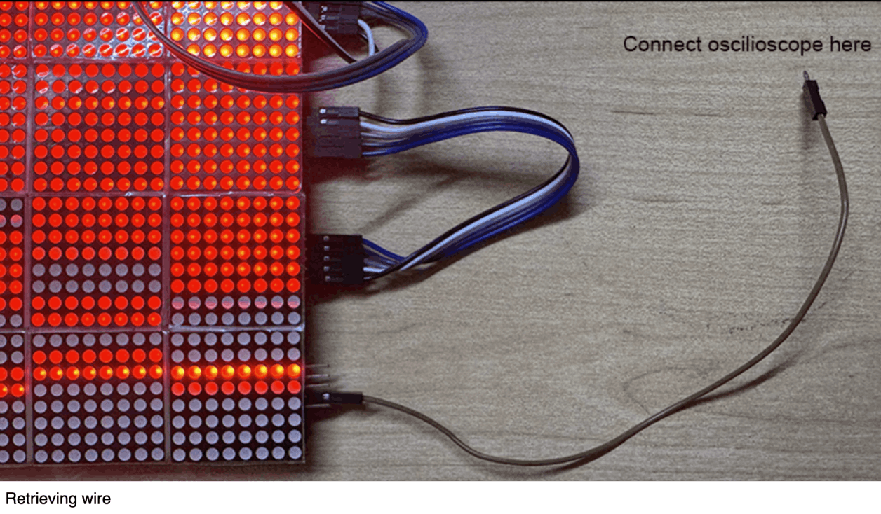
We used oscilioscope at N51's MAD studio to test the electric signals in my LED matrix. The matrix uses MAX7291 chip driver, and has 5 pins: VCC, GND, Data in, Chip Select, Clock. I kept my 2048 game's matrix layout, and used one extra wire to retrieve the signal from end pins.
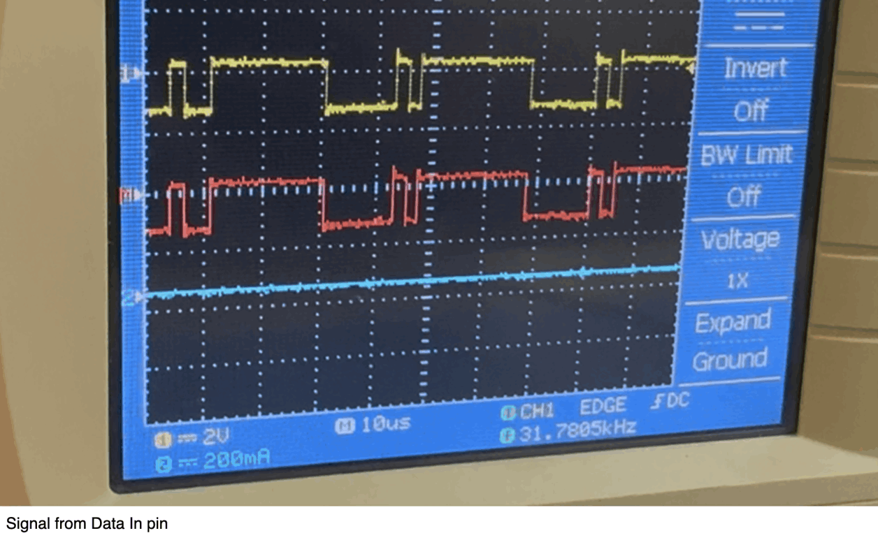
First, Xdd writes code to set all LED on every frame and test Data In pin, which showed a low/high signal. The cycle length is around 35 - 40 μs, which indicates the data update frequency is around 25 - 30 kHz. However, it is unsure what this cycle does, since to update the whole board of LED, 16 * 8 * 2 data will be sent (16 matrices, 8 bytes address + 8 bytes data for each board).
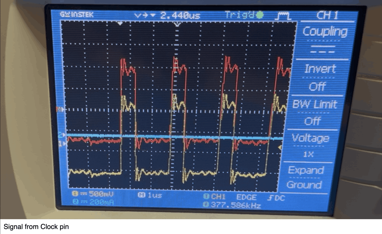
Meawhile, the clock pin showed a cycle of 2μs, which suggest a clock frequency of 50kHz.
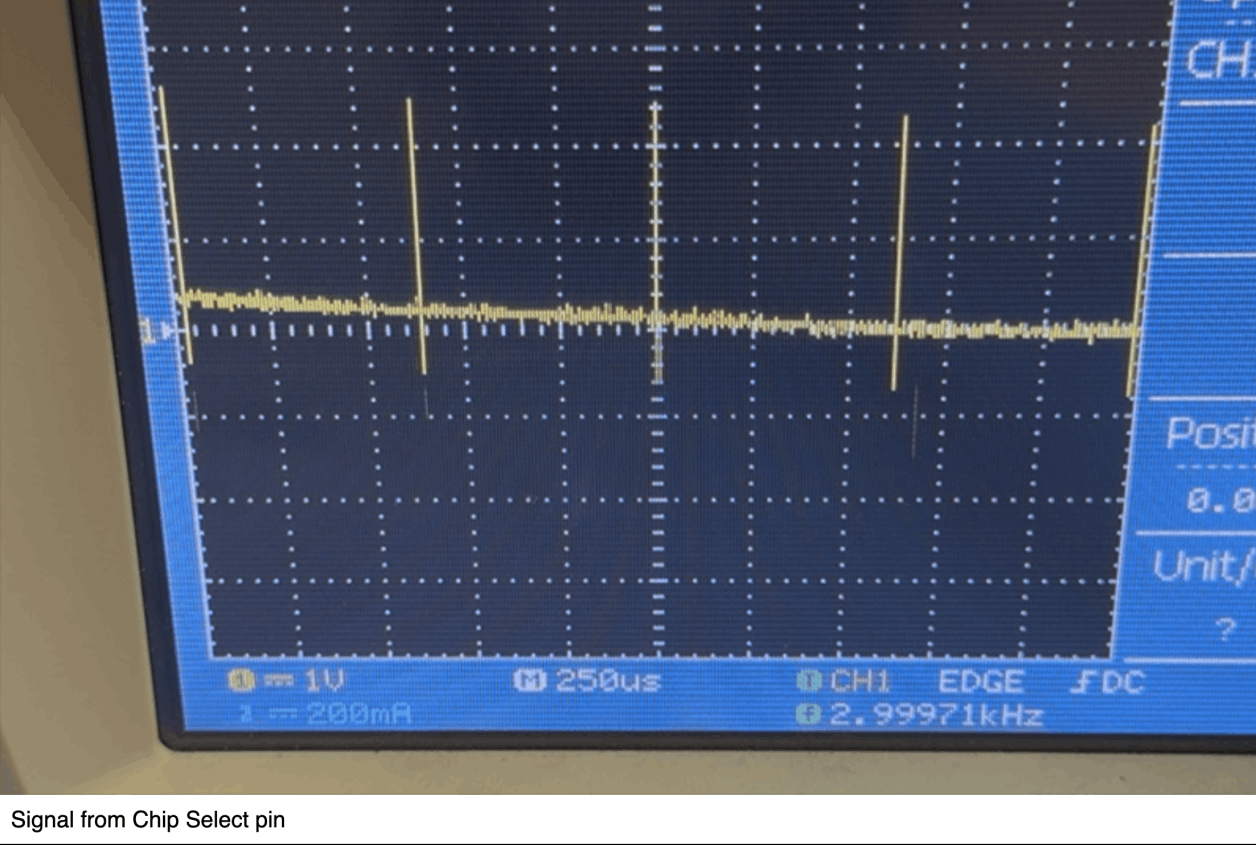
The Chip Select pin showed a cycle of 625μs, suggesting a data reading frequency of 1600Hz.
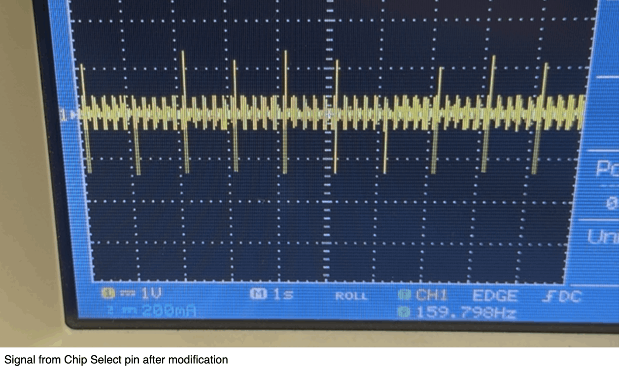
The Chip Select signal cycle should directly reflects how frequent LED data updates. Therefore, I modified the code to update LED once every second. Indeed, Chip Select pin showed an 1Hz signal.
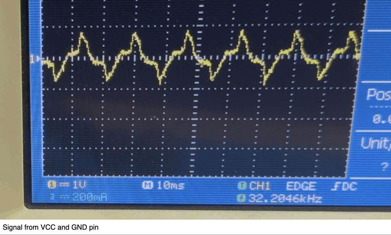
What we did not understand at all was both VCC and GND pins showed a wave of nearly 1V at 60Hz. We connected VCC to Arduino board's 5V out, and the board is powered by my MacBook without external power, which means we shouldn't get alternating current.
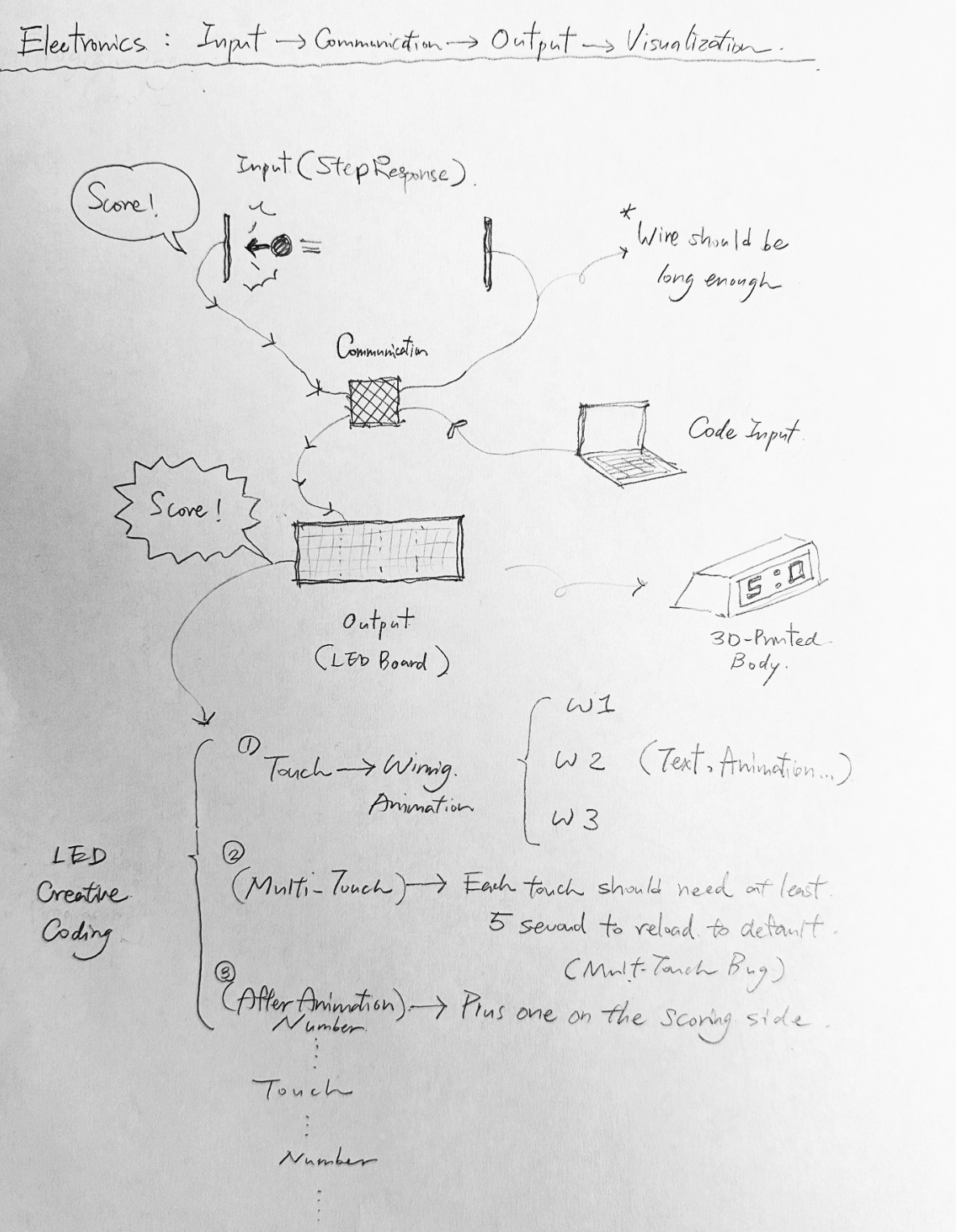
Here are some highlights of the electronic design:
(A) Input:
1. Step response
2. Detect number
3. Send to board
(B) Network System:
1. Receive data
2. Receive Codes (Creative visual coding)
3. Talk to LED
(C) LED Board :
1. Receive "touch" data: (number>xx)
2. Play a victory animation (random generates 3~5 animations)
3. Wait for 3~5 sec > prevent from multi-touching
4. Reveal score: plus one > reveal number
5. Receive "touch" data......
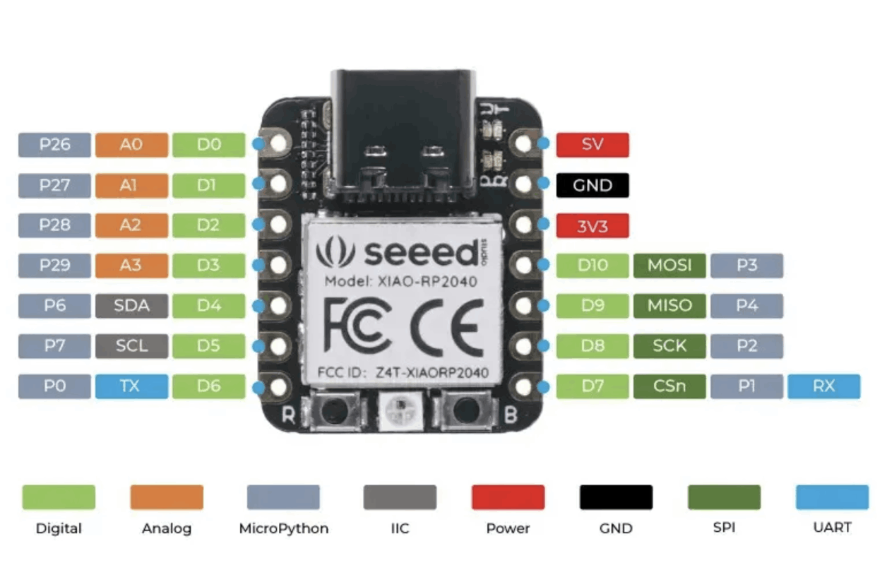
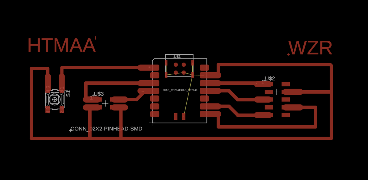
The schematic for my system is quite straightforward, and everything can be controlled by only one microcontroller. I am using XIAO SEEED STUDIO RP2040 due to it's much more reliable than the ESP series!
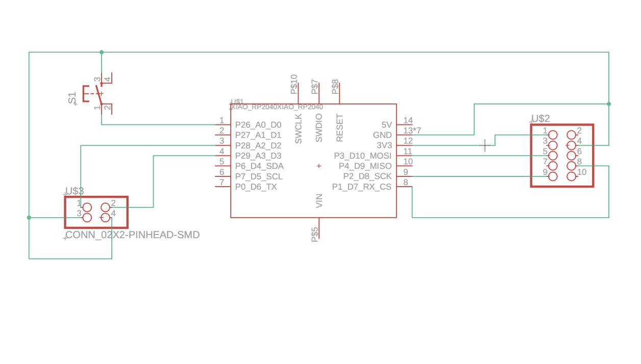
The input signal will sent to D2 and D3 once the end of factor is connected by an iron pinball. Once the microcontroller reads the message, it will talk to the LED matrix through the pins shown on the right. An extra button was added just in case of any future adjustments.
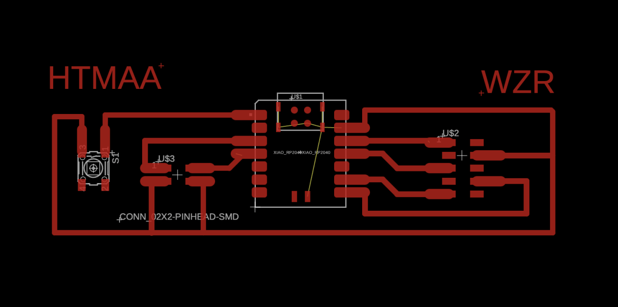
Based on my own experience, soldering often fails when the footprints are too small. Thus, I optimized the footprints to make them easier to access or keep distance from potential shorts.
WZR and HTMAA is a must!
No Code Website Builder