Electronics Design
Deciding and learning what to do:
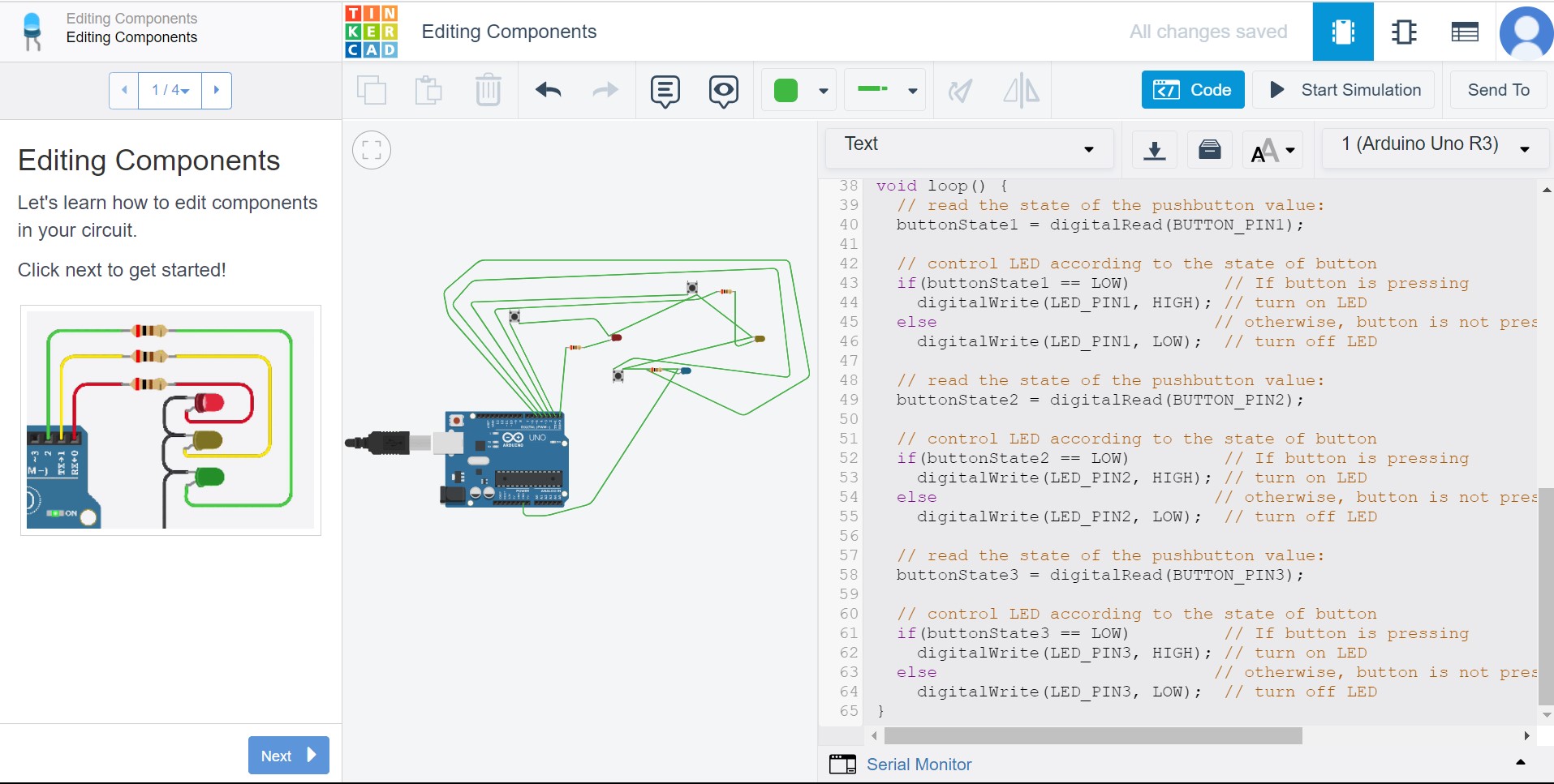
So I have very little experience with electronics, and so the first thing I was confused about was what exactly a board can do. So first, I decided to use TinkerCAD to help me understand how the components work. I decided to do a memory game with 3 buttons and 3 LEDS, and so I used the TinkerCAD simulation website to figure out how the connections will work and how the code will work. This really helped me since I have very little electronics knowledge and I was really confused on how to design a board.
Using EAGLE: My schematic
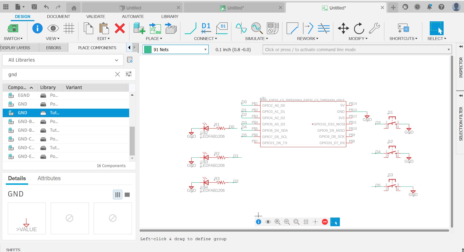
Since I have already been using Fusion 360, I decided to use EAGLE to design my board since it's part of Fusion. I followed the instructions from recitation. First, I started on my schematic. I chose to use the ESP32C3 as my microcontroller since I wanted the chance to experiment with its wifi and blutooth capabilities. Then, I basically recreated what I had made in TinkerCAD. I connected the first 3 pins to a resistor and then to an LED and then to ground. I connected the last 3 pins to a button switch and then to ground. I followed the advise to label the connections so that the schematic looks neat.
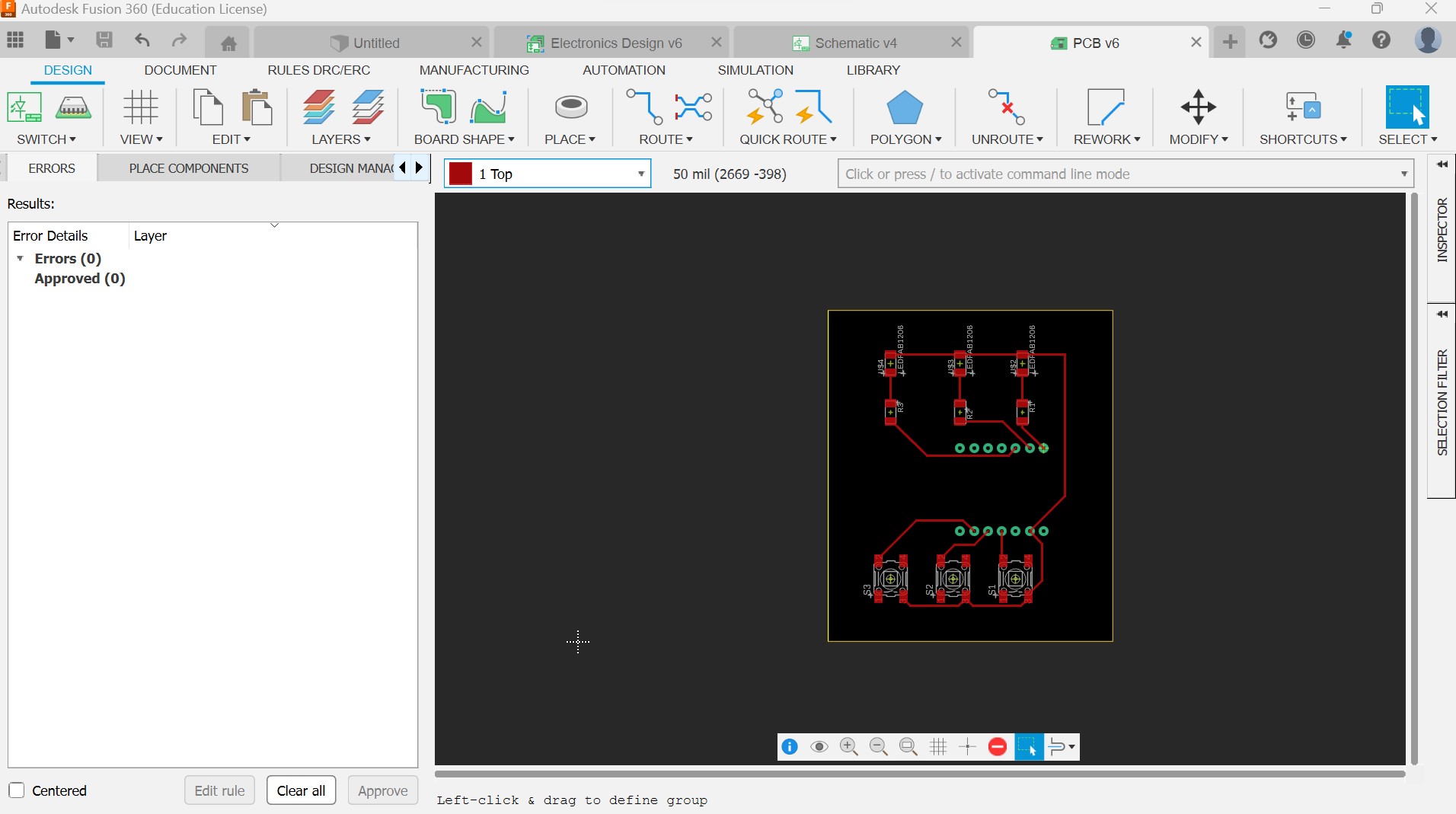
Final result:
After finishing the schematic, I then moved on to the actual PCB design. In EAGLE, the components and connections from your schematic are transported to the PCB design and you move around the components and connections until all design rules are met. Since the goal of this PCB is for it to be a memory game, I also wanted each button to align to an LED, so in this step I made sure the arrangement was also aesthetically pleasing. Once I was happy with my lines, I created the routes and my design was finished! Here is my final design.