Machine Building
Our machine: The Gershenforcer (automatic nerf gun)
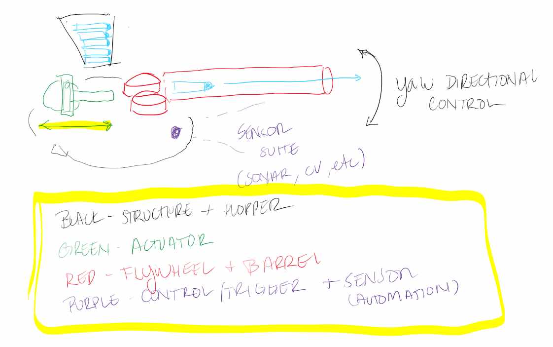
For our machine, we decided to build an automatic nerf gun. This machine would use a camera and machine learning to figure out where people are, aim the bullet launcher at the person, and fire the bullet at the person. We will have Neil's voice saying "Don't dribble in" as we're shooting people. We as a section decided to split into 4 sections: the actuator team, which will be responsible of pushing the bullet into the launching mechanism, the laucher/flywheel team, which will be responsible of building flywheels which will launch the bullets, the structure team, which will be responsible of constructing the moving mechanism of the launcher, and the software team, which will take care of the machine learning body tracking with the camera. Here is a picture of our machine design after our first meeting.
My contribution
I decided to be in the actuator team. The way we decided it would work is that we would have a servo attached to a gear, and the gear would then push another structure which would then push the bullet into the firing chamber. You can see the final design on our machine page here.
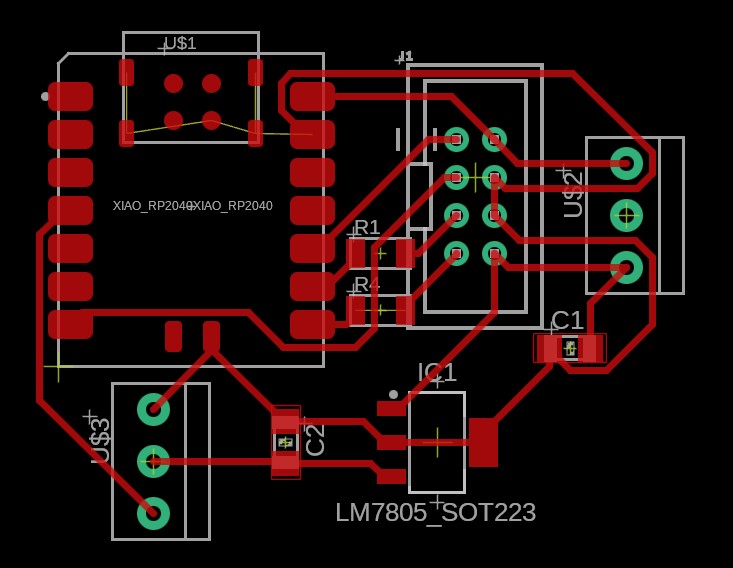
My other teammates focused on making the CAD on Fusion360. I was in charge of making the circuit controlling the servo motor we needed. We initially planned to use Modular Things to integrate everything, so I asked if the servo circuit things were already made so I didn't mess up anything when making it. There were some already made apparently but I was never able to get them. So, I decided to mill out the design they have on the Modular things github. I couldn't mill out the board using the gerber files since we needed a small tool and our Bantam mill in EDS didn't have a small enough tool. I then decided to just make my own board using the schematic provided in the github. I was confused on the buck converter, and when I asked Alec in EDS he said to just use a linear voltage regulator LM7805. So I made my board and the picture is my PCB design. I made it on Sunday and lab closed before I could mill it.
On Monday, we ended up deciding to not use Modular Things and instead have everything on one PCB (three servos, 2 MOSFETs and 2 DC motors). So, instead I helped out with integration in whatever I could. I helped with documentation on our group page, and I stayed with the group all night since I felt bad that I couldn't do more during the week. Yohan spent a long time integrating everything into 1 PCB since the pins from ESP32C3 were weird and caused weird bugs having all 3 servos running at the same time, and maybe if we had used Modular Things it would've been easier. Overall, I learned a lot seeing how everything worked together, and I wish I could've helped out more.
Final Product
Here's a video of our machine seeing Yohan and shooting him. However, shortly after this, the top of our machine broke from the bottom part which controlled the maneuvering. Since HTMA class was starting soon, we didn't have time to fix it, but both parts still independently work, and we could put them together by having better glue or making the bottom structure be able to support more weight. Our group documentation can also be accessed here.