HOW TO MAKE (ALMOST) ANYTHING
MAS.863 / FALL 2011
KELLY SHAW
M.ARCH LEVEL III
03 / PCB DESIGN, FABRICATION, AND ASSEMBLY
04 / WATERJET CUTTER AND CNC MILLING
11 / INTERFACE AND APPLICATION PROGRAMMING
12 / MECHANICAL AND MACHINE DESIGN
13 / NETWORKING AND COMMUNICATIONS
WEEK 10 / OUTPUT DEVICES
This week was a struggle to learn about Charlieplexing for my final project. While I didn't get a chance
to finish designing and programming a board for my final project idea, this week was more about
answering the following question:
CHARLIE-WHAT?
In plain terms I learned that Charliplexing is pretty much driving lots of LEDs with only a few pins. It's
a technique named after Charles Allen at Maxim.
I had a lot of trouble understanding how it works but after doing some research online and talking to
some TAs (Thanks Matt and Bryan!) I decided to include my basic understanding of how it works. My
assumption is that some other EE-impaired student will find it helpful because it really is very neat.
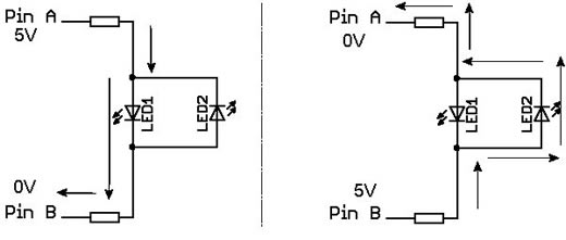
Charlieplexing is also known as 'complementary drive'. With a microcontroller a pin can be set to
'0' or '1' (0V or 5V at output). In the diagram below, if you have power flowing from Pin A to Pin B
(right side), LED1 will light up due to current flow, while LED2 will not because it's oriented in the
opposite way. If you switch Pin A and Pin B, current will now flow through LED2 and LED2 will light up
(left side).
[complementary drive]
Great you say, two pins driving two LEDs. How is any different from giving each pin an LED?
If you extend the matrix you can start to see how useful Charliplexing is.
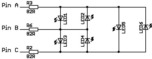
The diagram below shows 3 pins driving 6 LEDs (with N pins, you can potentially drvie N*(N-1) LEDs). In
my project I plan on needing at least 50 LEDs so I would need at least 8 pins to drive up to 56 LEDs. If
you disconnect Pin C, Pins A and B work just like before, meaning that with 5V on Pin A and 0V on Pin B,
LED1 will glow and nothing will glow on LED2, and vice versa.
If you disconnect Pin B and put PinC to 0V, then LED5 would glow, etc. In this case, there is still current
flowing between LED1 and LED3 even though Pin B is not connected. However, current likes to through
the path of least resistance and with two LEDs to split the voltage, these LEDs will not glow visibly.
Pretty much most of the current want to flow through the other LED.
[3X6 Charlieplexing]
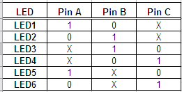
We are able to 'disconnect' pins through the microcontroller by setting output pins to be inputs. When a
pin is programmed to be an input, it has a very high resistance to the pin. When there's a high resistance
we can treat that pin as being disconnected. In the table below you can see a matrix for Pins A-C and
the possible combinations you can use to illuminate each LED.
[tri-states]
PRACTICE MAKES PERFECT
I really wanted to actually understand what I was soldering together this week so I didn't get much farther
than doing Neil's example. But doing so helped me to learn more about Charliplexing and I'm working
towards modifying the design to accomodate my final project designs.
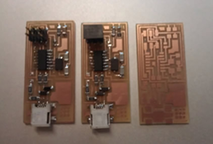
One thing I did end up doing was remaking my FabISP. For some unknown reason it just stopped
working...
[the one that did work, now works and will work]
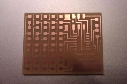
[milled board]
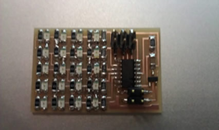
[one very meticulously stuffed board]
[NEIL's CHARLIEPLEXED ARRAY]
NEXT: CHARLIEPLEX DESIGN FOR GHOST CHAIR