HOW TO MAKE (ALMOST) ANYTHING
MAS.863 / FALL 2011
KELLY SHAW
M.ARCH LEVEL III
03 / PCB DESIGN, FABRICATION, AND ASSEMBLY
04 / WATERJET CUTTER AND CNC MILLING
11 / INTERFACE AND APPLICATION PROGRAMMING
12 / MECHANICAL AND MACHINE DESIGN
13 / NETWORKING AND COMMUNICATIONS
WEEK 03 / PCB DESIGN, FABRICATION AND ASSEMBLY
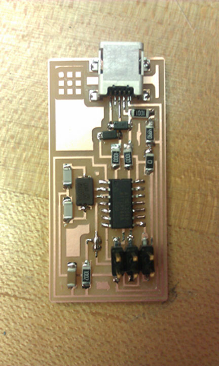
This week's assignment was to make the FabISP in-circuit programmer. We were tasked
with milling the circuit board, stuffing it with components and programming it. The result
would allow us to program other microcontrollers via USB.
[finished board]
01. VINYL CUTTING [at last!]
Since I didn't get a chance to try vinyl cutting and I was interested in the idea of flexible
circuits with the potential to be attached virtually anywhere, I started the week by trying to
just cut, transfer and weed the the predesigned circuit board. I went to a tutorial held
by Jie Qi [thanks jie!].1. Loading material and setting up the files.
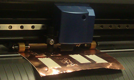
> We loaded the copper sheet into the Roland Vinyl Cutter, making sure the grippy wheels
were grabbing onto the material and that the material was lined up with the gray lines on
the machine.
> After hitting the R or L arrow on the machine to display the Roland menu, we selected
the piece and hit ENTER to autozero the Roland for our material. It's important to remember
to account for margins on your material which are about the width of the grippy wheels.
We used the navigation arrows to find a spot on the material to start cutting and then hit
ORIGIN SET to set the zero.
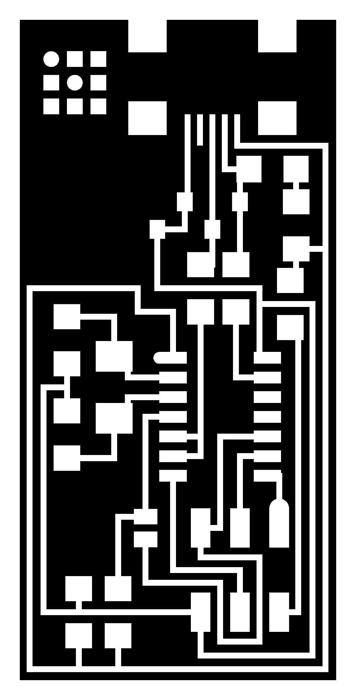
> We ran the Fab Module and sent the .png file to the vinylcutter, MAKE PNG. While we
used most of the default presets, Jie recommended that we make the traces slightly wider
in diameter since the blade was so fine. We hit MAKE PATH and SEND IT.
SETTINGS: default settings, diameter = 0.25 mm, force = 80
[.png file]
[circuits being cut on the Roland Vinyl Cutter]
2. Transferring
After getting a piece we were happy with we transferred the circuit to our substrate using
masking tape. Essentially all we had to do was rip off a piece of masking tape, stick it
firmly to our cutout, slowly [...slowly!] pull up the circuit and then transfer it to our material.
3. Weeding
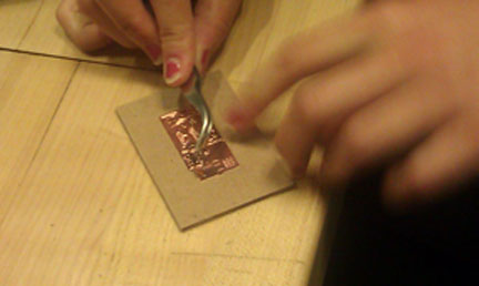
This was the trickiest part. The first pass I had with weeding I had transferred the piece to
a nice piece of cardboard. Weeding involves removing all the pieces you don't want in your
design. Using the tweezers to peel away material I didn't want, while holding a pencil tip
[good for tiny, tiny details] to the stuff I wanted to keep, I spent about 45 minutes weeding
from the cardboard substrate. I discovered that the material was actually sticking a little
too well to the copper [and slightly ripping my chip board] and wanted to try something less
adhesive.
[weeding with tweezers]
[resulting piece on cardboard = hard to weed]
As a second try I transferred to another piece of epoxy. SUCCESS. This weeding process
took a lot less time because I could easily peel the copper sticker from the vinyl substrate.
[resulting piece on vinyl = much easier]
In the end I found the weeding process to be pretty theraputic and learned that it was actually
helpful to have fingernails when weeding.
For more on the vinyl cutting process click here.
On to the actual assignment...
02. MILLING
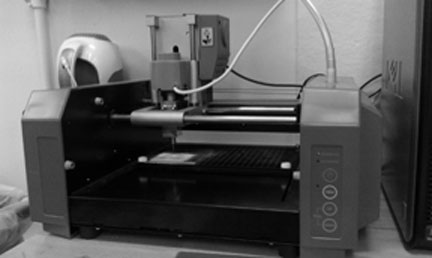
We were trained on the Modela milling machine to cut our circuit boards. In addition to using
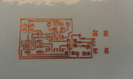
the .png file above as our trace [using a 1/64 drill bit], we also had to mill out the board from
from the FR1 copper plate [using a 1/32 drill bit] using the .png below.
[outline .png]
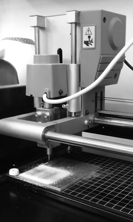
[Modela milling machine]
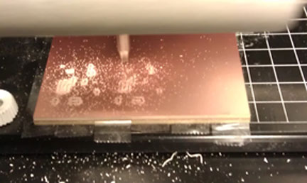
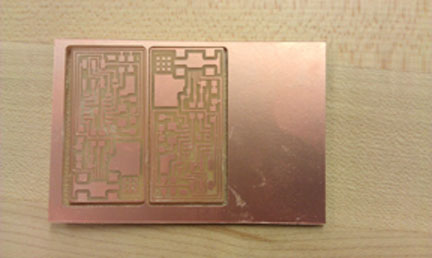
[milling out two boards]
[1/64 bit in action]
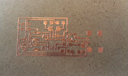
[resulting two boards]
I had an easy time with the Modela but there were a few important take-aways I saw from
observing other people:
> Be absolutely sure your sacrificial board [the one underneath your actual piece] is
clean and even.
> When mounting your board to the Modela, make sure your double stick tape doesn't
fold over on itself. Any type of uneven surface seems to make this little mill do crazy things.
> If your traces aren't cutting evenly it may be time to check and replace the drill bit.
> ALWAYS mill more than one board. You will probably screw one up.For more on milling with the Modela click here.
03. SOLDERING
Having never soldered anything in my life this was the hardest part of this week's assignment
for me. Good thing I milled two boards. For this exercise we had to stuff our board with the
schematic shown below.
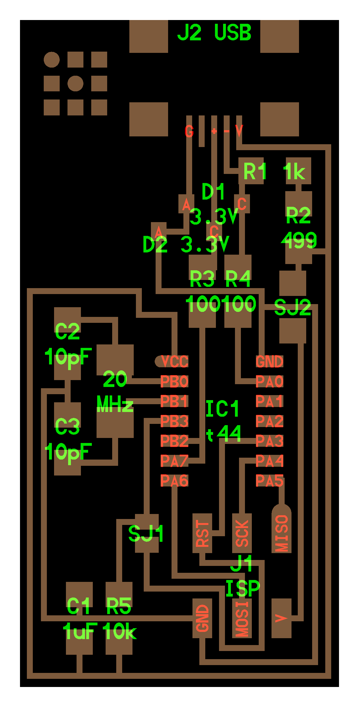
[board schematic]
David Costanza ran the tutorial for soldering and I found his technique to be easy to get the
hang of. Using a setting of 80, I would put a drop of tin on one pad. Then, holding my
component with tweezers in one hand, I would reheat the drop with the iron and tack a leg of
the chip to the pad. This helped to hold my piece securely in place while I soldered around the
rest of the chip. For the really narrow traces, I found that putting a drop of tin on the iron and
then dragging the iron along the joint was also a good technique.
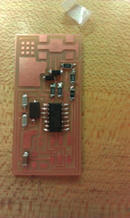
[partially soldered board]
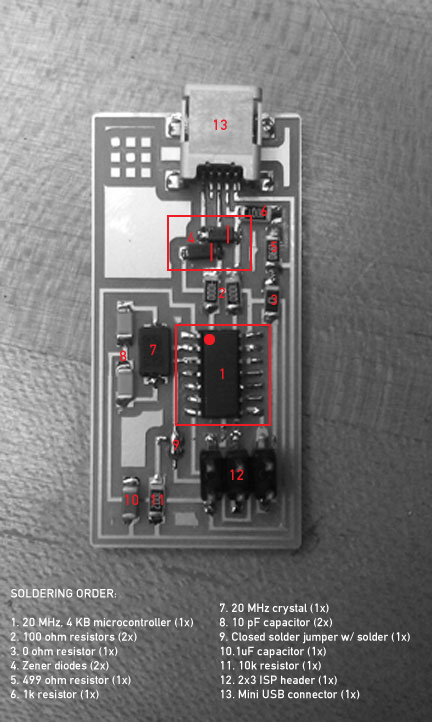
I soldered my first board in the order shown below. Some things to watch out for are the
orientation of your microcontroller [dot goes on the top left] and the two diodes [lines go on
the right].
[soldered component order]
04. PROGRAMMING
I was now ready to program my board. Costanza had already installed an in-system
programmer on his computer so we plugged my FabISP into the mini USB and the 6 pin
cable of the other programmer. The result was a red light indicating that my board wasn't
getting power. I checked all my connections and tried reflowing a few of the suspect joints.
While I eventually got a happy green light, when we ran the sudo make fuse command, I
saw the following error:
make: ***[fuse] Error 1
johnnystaccato@ubuntu:~/Downloads/firmware$ sudo make fuse
avrdude -c avrisp2 -P usb -p attiny44 -U hfuse:w:0xDF:m -U lfuse:w:0xFF:m
avrdude: stk500v2_command(): command failed
avrdude: stk500v2_command(): unknown status 0xc9
avrdude: stk500v2_program_enable(): cannot get connection status
avrdude: initialization failed, rc=-1
Double check connections and try again, or use -F to override this check.
We spent the next 2 hours trying to debug my FabISP. Unfortunately it involved re-soldering
and re-flowing almost all of the components on the board. I'm not sure why this board did
not want to cooperate but I think in the end I might have burnt out a few of my components
since I may have been a little heavy-handed with the iron. I decided to go home and sleep.
The following morning I came in early and re-soldered a new board on my second milled-
board. This time I downloaded the firmware.zip and installed CrossPack on my Mac
(the development tools for AVR microcrontrollers). I edited the Makefile to change the line:AVRDUDE = avrdude -c usbtiny -p $(DEVICE) for my programmer (-c avrispmkii -P usb).
I ran the make program command line to program my second FabISP and finally got it to
work! Once the FabISP had been programmed, I removed the 0 ohm resister and opened the
SJ1 solder jumper. I was able to verify that everything was working when I connected the
FabISP to my computer and it appeared as a USB device, which I could now use to program
other microcontrollers and FabISPs.
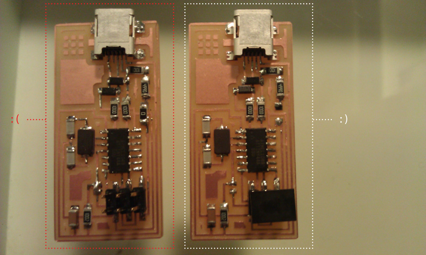
[L: funky board 01, R: successful board 02]
For more information on making the FabISP, click here.