HOW TO MAKE (ALMOST) ANYTHING
MAS.863 / FALL 2011
KELLY SHAW
M.ARCH LEVEL III
03 / PCB DESIGN, FABRICATION, AND ASSEMBLY
04 / WATERJET CUTTER AND CNC MILLING
11 / INTERFACE AND APPLICATION PROGRAMMING
12 / MECHANICAL AND MACHINE DESIGN
13 / NETWORKING AND COMMUNICATIONS
WEEK 04 / WATERJET CUTTER AND CNC MILLING
This week's assignment was to make something BIG using computer-controlled machining. In
this case we were given tutorials on the ShopBot Mill/Router and the OMAX Waterjet.
I wanted to test out the construction feasibility of my proposed GHOST CHAIR and decided to
try milling a prototype from medium density fiberboard (MDF) on the ShopBot.
01. MODELING
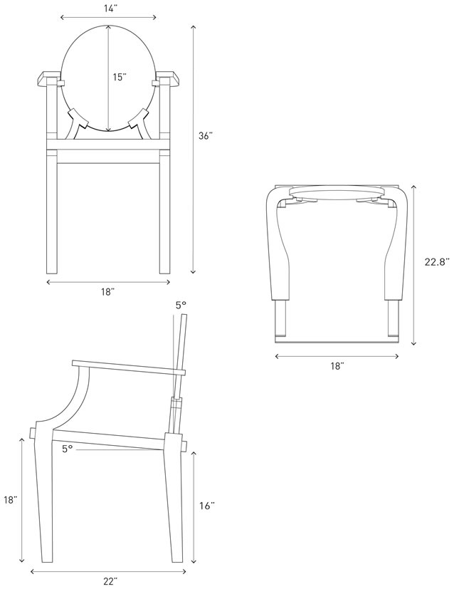
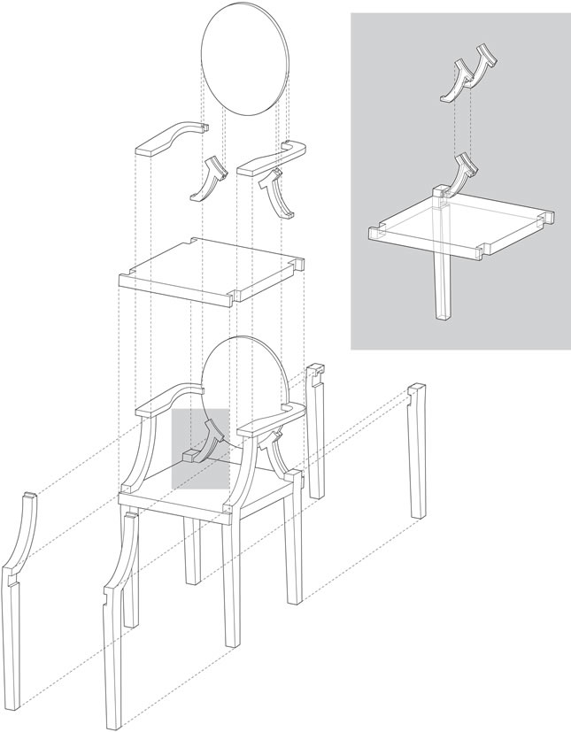
My first task was to decompose Philippe Starck's original chair into elements I could 2D-mill.
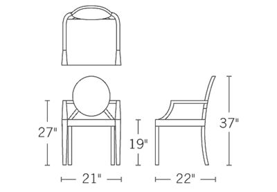
[Philippe Starck Ghost Chair dimensions]I modeled the chair in Rhino and did a few iterations on how to achieve a more comfortable
chair back and seat angle angle (5 deg.). The final model chair dimensions and exploded
construction axon are shown below.
[modeled chair dimensions]
[exploded construction axon]To mill the components I used two thicknesses of MDF. For the chair back, arms and back
supports I used 0.75'' MDF. For the chair base and legs I used 1.5'' MDF [two pieces of 0.75''
laminated with wood glue]. Because I was pocketing the notches to the full profile of most of
the chair components, Costanza gave me a nice tip to extend the pocketing path about the
diameter of my tool past the profile path. This would ensure that my pockets extended all the
way to the edges of each piece.
[1.5'' and 0.75'' MDF cutfile layouts]
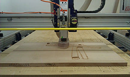
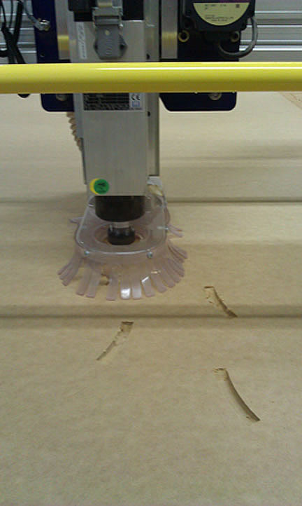
02. MILLING
MDF cutting tool bits used:
1/4'' shaft for cutting 1.5'' piece
1/8'' shaft for cutting 0.75'' piece
Tool settings:
- Pass Depth: diameter of tool or smaller
- Stepover: 50-70%
- Spindle: 12,000 RPM
- Feed rate: 120 inch/min
- Plunge: 30
There were about a million buttons and screens for operating the ShopBot. I've include
a step-by-step process I took notes on below:
Pocket: Milling partially through
Profile: Cutting all the way through
- Export file as DWG of DXF
- Use PartWorks to set up file. [ShopBot Bed = 5'x10']
- Set material thickness in dialog box [Measure material]
- Uncheck ''Use Origin Offset''
- Check ''Center Data in Job'' which puts stuff in the white box
- Set Origin Locally
- Hit ''OK''
- Remember to close curves
- Create Fillets [Under Edit Objects]
- Set Tool Radius [Tool shaft/2]
- Choose Dog Bone, T Bone, or Normal Fillet types
- Set curves/cuts [Pocket and Profile cuts]
- Be sure to set cut depth past the material thickness [ex: MDF was 0.75'', used 0.77'']
- Depth of cut should be no more than diameter or tool
[ex: 0.77/6 = .128, used 7 passes]- ''Tool Edit'' to change tool sizes [check with TA or online depending on material]
- Profile: Select Inside/Outside cut of lines
- Tabs: Keep your material from lifting
- Cuts in the order you've listed, so make sure profile cuts are last
- Save paths and output file
- If you have a tool change be sure to save that tool path as a separate output file
- Turn on machine, RED knob.
- Open ShopBot, if necessary, hit BLUE reset button to clear dialog boxes.
- Type K or hit YELLOW Keypad Icon
- Change tool:
- Loosen:SILVER L, BLACK R, pull together
- Tighten: Black L, SILVER R, pull together
- Vacuum: should be at the same level as tool bit, adjust with back screw
- Tool bit: should be out about the thickness of the material
- Locate XY:
- Arrow keys to locate
- To set XY: Zero [file menu]: Zero (z) axes (X&Y)
- To set Z:
- Place plate under tool [make sure it's flat!] and clip alligator clip to drill bit
- Cut [file menu]: Zero Z, Axis with zero plate, hit OK
- Unclip, put back the plate and clip
- Turn on vacuum
- Put key in slot, turn live [90 degrees]
- Load file, hit little start [GREEN button]
- Pause: click anywhere
- Emergency: RED button kills everything
* Be sure not to lose the XY setting between cuts when you are changing tools and re-setting Z
* SMALL or WEAK needs BIG or STRONG [keep this in mind when partnering!]
[profile cutting chair legs]
[pocketing chair back supports]
[0.75'' MDF cut sheet]
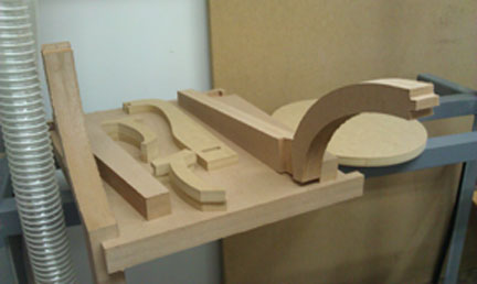
[chair components]
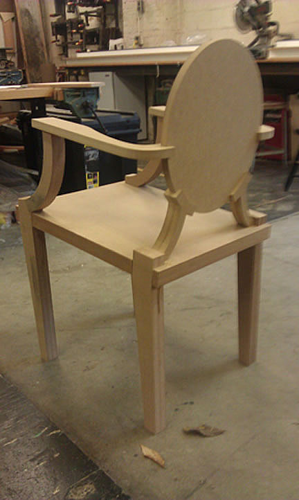
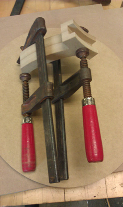
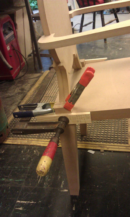
03. JOINING/ASSEMBLY
The third phase of my BIG week was putting the milled parts together. MDF cut very easily on
the ShopBot but there were some slots that were off by about 1/16''. Not wanting to recut my
my pieces, I took everything to N51 and with the help of Chris Dewart + Costanza made a few
minor adjustments. The chair ended up press-fitting together pretty nicely but because the MDF
deformed after one or two fits, I used the slots as registration and glued the final pieces
together for stability.
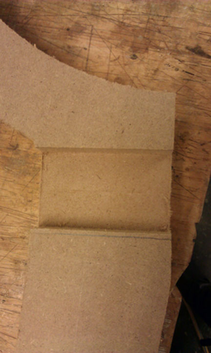
[excess material needing to be chiseled]
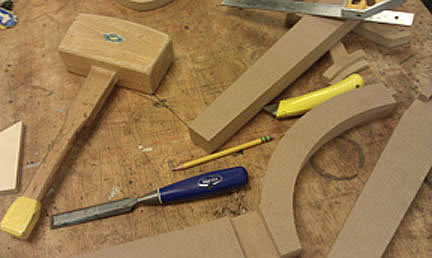
[chiseling tools]
[woodglue is fun]
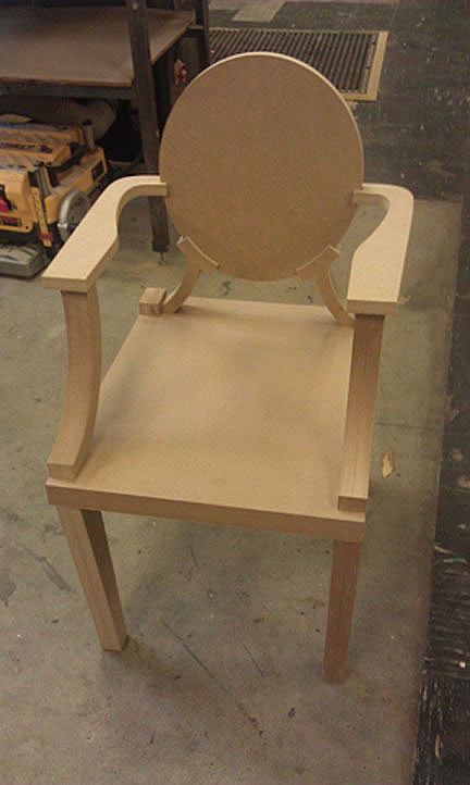
[front + back]
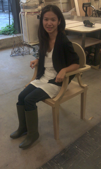
[and it holds weight...]
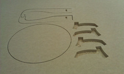
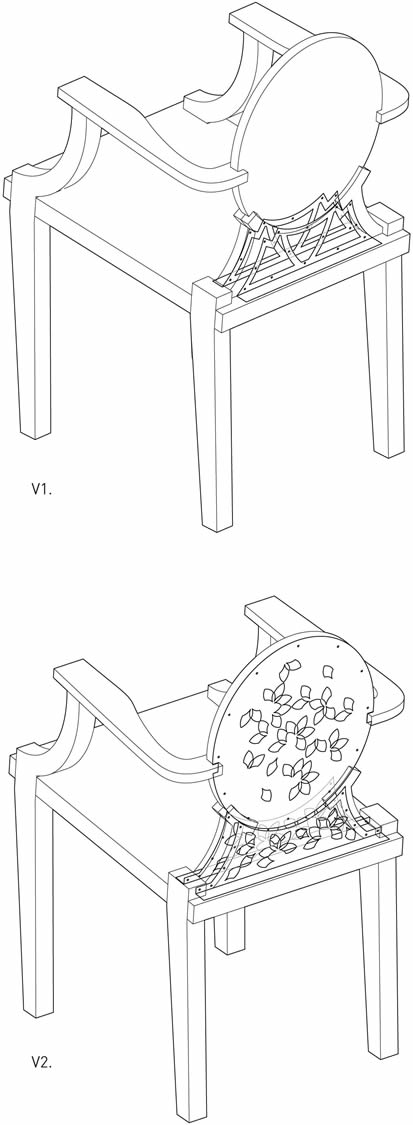
04. WATERJET SOME SUPPORTS
I really wanted to get on the OMAX, so as part of week 4.5 I decided to try waterjet cutting
some alternatives for bracing the chair back. I see some potential for waterjet cutting a frame
to keep the chair back hollow for electrical components.
The first thing I thought about were where the joints were the weakest and I decided to model
some aluminum braces in Rhino which would either sit inbetween the chair back supports
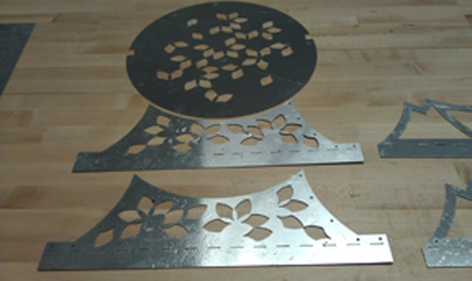
[V1.] or be nailed to the outside on the chair seat [V2.].
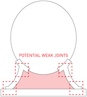
[red area = bracing zone]
I won't go into tons of detail about the workflow because there's a pretty nice tutorial available
on the RPL site. I recommend reading it even though the monitors walk you through the steps.
When the RPL monitor [thanks Moe!] and I tried to import my .dxf into OMAX Layout, the program
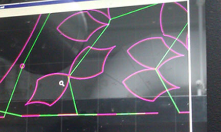
had trouble making the toolpath since the curves on the leaf design were intersecting. I took
it back into Rhino and separated all the closed curves and the path was auto-generated perfectly
the second time.
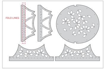
I wasn't sure how to best make the dashed lines to create a fold in 1/16'' aluminum but I opted
for 0.5'' dashes with 0.5'' spacing. I would later discover that about 80% line removal was a
better estimate.
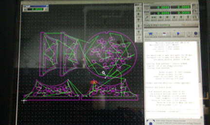
[cut file + path file for OMAX Make]
[intersecting arcs confuse the OMAX]
[toolpath]
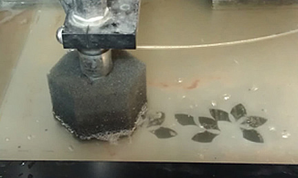
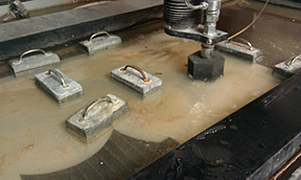
[cutting]
[keeping the aluminum down while shifting weights to clear the machine path]
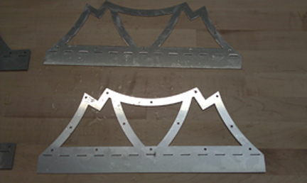
[V1. bracing cut, the folds didn't work out but I will just bend them in the metal shop]
[V2. bracing cut with chair back design]