Week 5: CNC Machining: "Make Something Big"
This week we had to use the ShopBot, a large 3-axis CNC milling machine with a bed size of 5 ft by 10 ft, to make something big.
Inspiration
I wanted to make a piece of furniture this week. I have always been fascinated by Adirondack chairs, which are classic simply designed and constructed outdoor chairs.
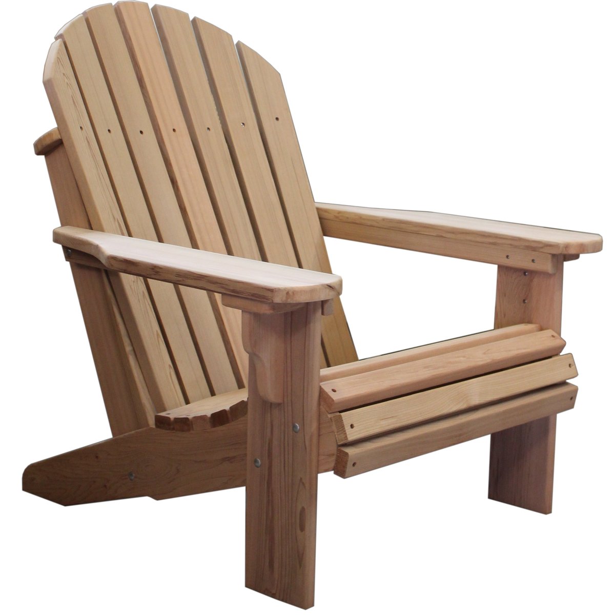
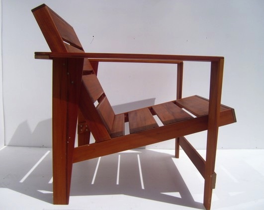
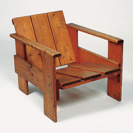
I wanted to go for a more modern take on the Adirondack chair, and took these two examples as inspiration. The chair on the left is a modern Adirondack chair I saw on Etsy (the seller Nyendesigns). I like that the chair has the clean, straight lines while still preserving the seat angle and chair height that is characteristic of a classic Adirondack chair. The chair on the right is a crate chair designed by Gerrit Rietveld, a Dutch De Stijl furniture designer and architect. These chairs, made during the 1930's economic crisis, were crafted from affordable crate wood packing material.
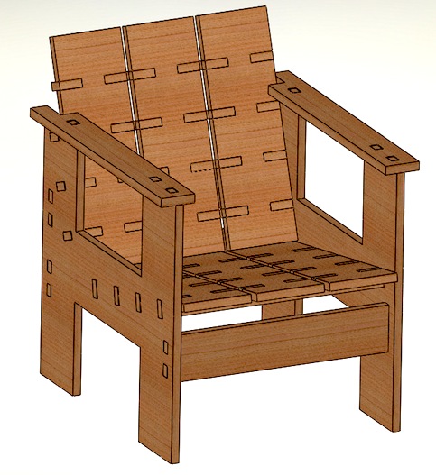
My Press-Fit Version
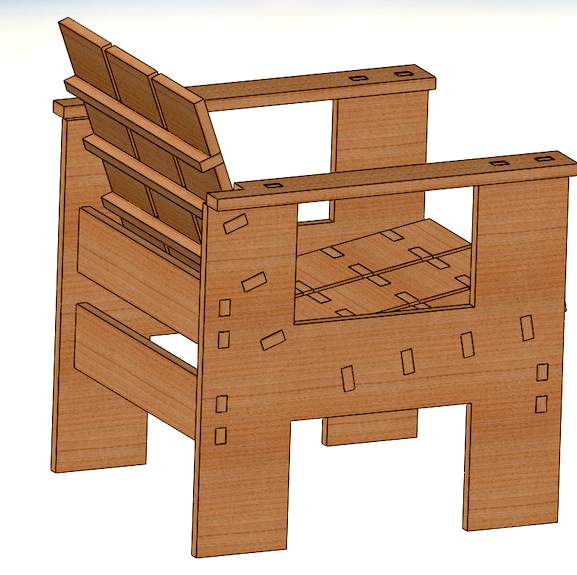
I decided to make my chair press-fit as an extra design challenge, and also for easier construction. All of the pieces are designed to be cut with 2D paths from a flat piece of wood. Here is my SolidWorks model.
ShopBot-ing!
Then, I made my digital design reality after a weekend of using the ShopBot to cut my pieces and then putting the pieces together. I bought (nominally) 3/4 inch thick cherry plywood from Home Depot. The sheet was 4 by 8 feet, but I had to cut down to two 4' by 4' pieces to be able to more easily transport it home. When I measured the thickness, I found it was actually 0.7 +/- 0.1 inches thick. So I designed all the joints in my pieces to fit exactly for 0.7 inches and planned for sanding down pieces or gluing together pieces as needed afterwards.
I layed out all my pieces on two documents in Adoble Illustrator sized to the sheet of plywood.Then I exported the .DXF files and imported them into PartWorks, the software that is used to create the toolpaths for the ShopBot. I made outside and inside toolpaths seperately. I used the PartWorks software to modify my joints with dog-bone shapes. This is necessary since the tool radius makes it such that the joints can't be cut with perfect sharp corners. Joints with these designs make it posisble for the pieces to fit togehter such that the edges are flush with each other. I used a 1/4 inch end diameter mill, so I made my dogbone features have radii that were equivalent to 1/4 inch for most features, and 0.13 inches for smaller features. The lower limit for the radii of these dog-bone features is the radius of the tool.


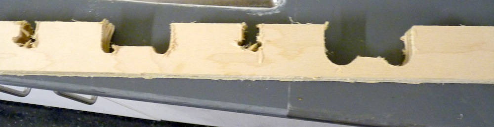
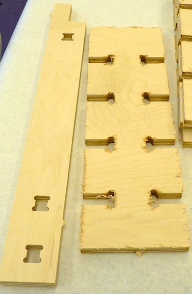
NOTE OF CAUTION: Sometimes when you modify the dogbone joints, it is easy to accidentally distort the dimensions. So make sure you double check the dimensions of all your parts and joints before cutting. I learned this the hard way. The dimensions didn't look obviously distorted on the screen, but the pieces were clearly wrong after cutting. Here is an example of a part that got cut with the wrong dimensions. The slots were supposed to be the same size.
Another tip: join all the vectors in PartWorks so that the toolpaths are continuous. This will reduce cutting time and make the cuts smoother.
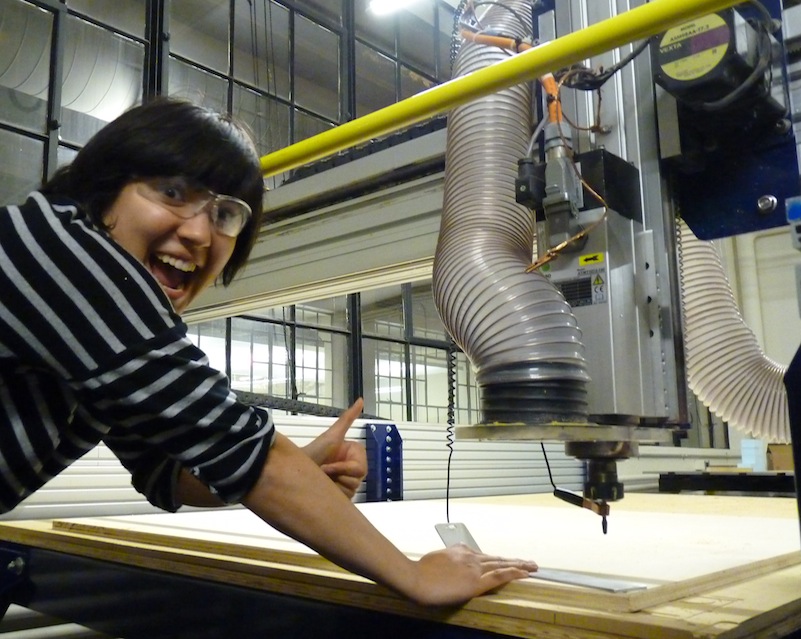
Now that the files are prepared (properly and with the right dimensions), onto cutting! First I used a drill to secure the plywood to the bed with screws around the perimeter. Then, I zeroed the x, y, and z dimensions. Here I am ecstatic about using the handy plate that comes with the shopbot for automatically zeroing the z-axis.
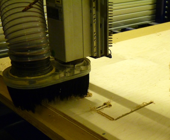
I used a speed of 12000 rpm, a feed rate of 100 inches per minute, and a plunge rate of 50 inches per minute. Unfortunately, the endmill was super dull, and the wood splintered like crazy.
Finishing and Assembling
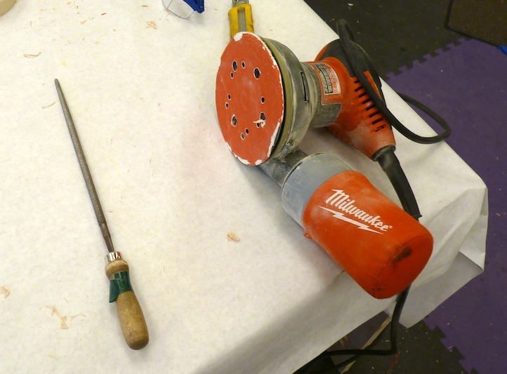
After cutting, I had a lot of pieces that needed sanding. I used a rotary sander, a belt sander, and also a round file for the joints.
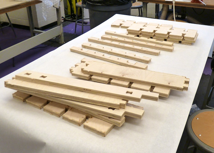
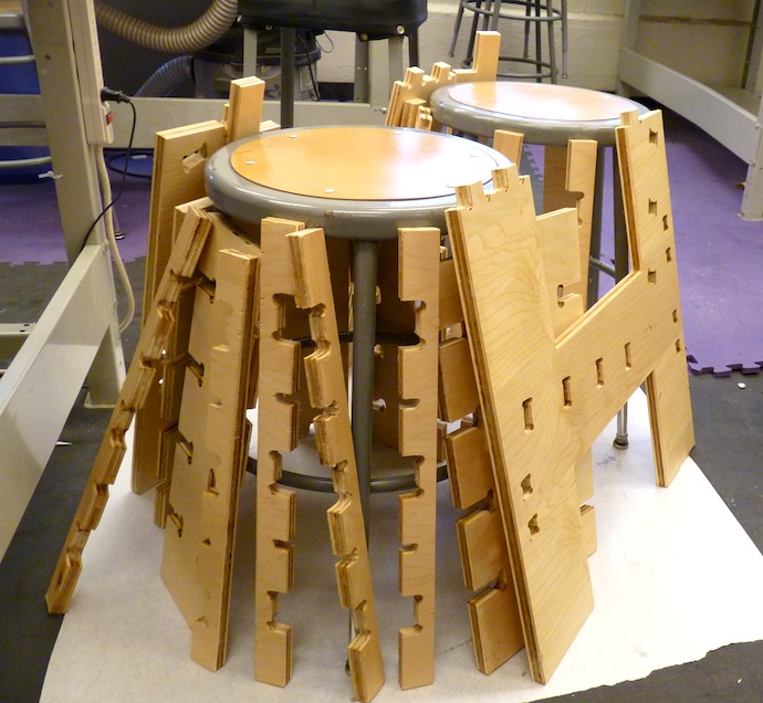
After sanding, I finished the wood using mineral oil, which is non-toxic, food safe, and cheaply and easily obtained from any pharmacy. I used paper towels to apply the oil generously. This protects the wood and gives it a nice color. Here are the pieces post-oiling propped against some stools to dry overnight.
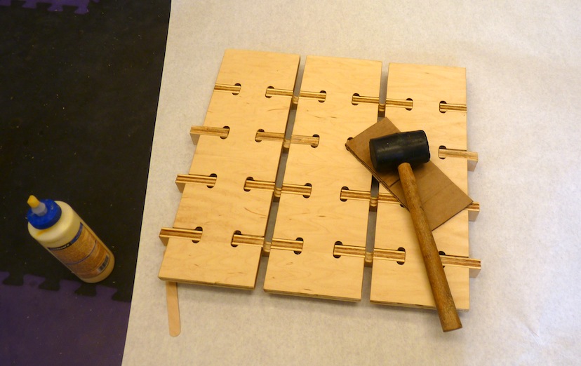
Then I assmbled the pieces. First, I assmbled the seat and the chair back using the boards and the slats. I used wood glue to hold it together permanantly and a mallet (with scrap cardboard between the mallet and wood to prevent marking from the rubber) to get the pieces to fit together.
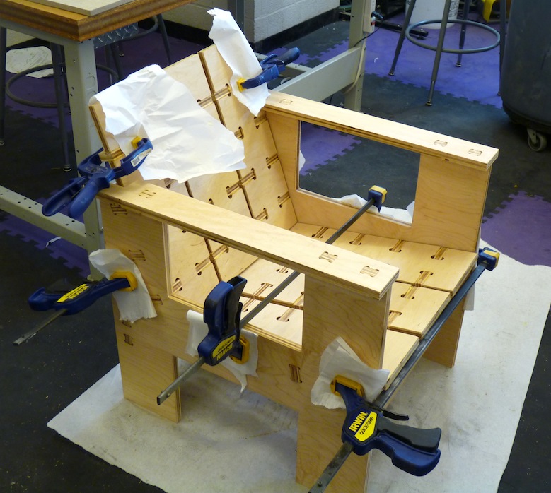
Then I assmembled the chair pieces together. After gluing, I clamped the chair together while the glue dried overnight. I used paper between the clamps and the wood to protect the surface of the wood.
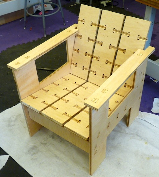
Here is the chair fully assembled.
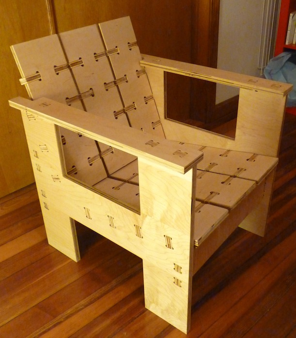
I took it home and I think it looks rather nice in my living room!
DXF files for the chair:
Note: This is designed for sheets that are 0.7 inches thick. The dogbone joints are not in these files. The straight joints must be modified before cutting (I did this step in PartWorks, though this can also be accomplished with a variety of design tools).
back and seat boards (cut 6)
slats for the boards (cut 7)
slat for the top of the chair back (cut 1)
sides (cut 2)
horizontal support bars for sides (cut 3)
arm rests (cut 2)