Week 8: Embedded Programming
The assignment for this week is to program the boards we made for the electronics design assigment. Two weeks ago, I made a simple board with one button and an LED.
Reflex test game
I came up with a reflex test game that involves just a button and an LED.
In this video, I play the game twice. I win the first time, and lose the second time.
The game works as follows:
- The button is pressed to begin the game, and the LED lights up to indicate the start.
- After a number of seconds randomly between 1 and 10, the LED quickly flashes, and the player presses the button as a response.
- If the response is quick enough (less than half a second), the player wins and the LED blinks in celebration. If the response is too slow, the player loses and the LED fades in disappointment.
- The game then resets itself and can be started again by pressing the button.
Here is the code for the game.
Programming the board
First, some troubleshooting...
When I first tried programming my board, I got some errors due to shorting. So I took a look at my board to see where the problem was. First, I noticed that I had used the wrong resistor for the LED (not related to the shorting, but a problem nonetheless). I had used a 500K ohm resistor insteady of a 500 ohm resistor. Now I know what that last digit on the resistors means... it's the power on 10 that you multiply the first three numbers by. I de-soldered the microcontroller to see if there were any weird connection problems under there. The best way to de-solder these is by holding onto the microcontroller with the tweezers a few inches above your working surface and using the heat gun to melt the solder and let gravity pull the board away from the component. And I found the problem!
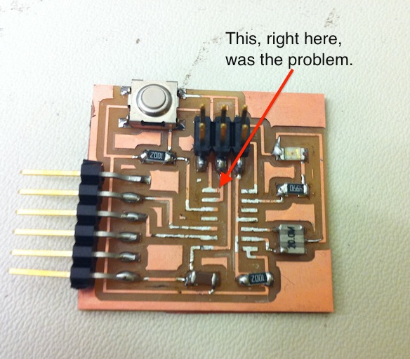
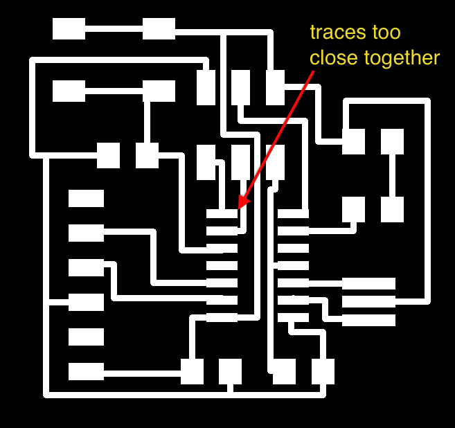
One of the traces on my board for the microcontroller pins was way to close to another trace, and the milling machine wasn't able to cut it away. I solved this problem using the extremely high-tech method of scratching away at the copper with an x-acto knife and using a multimeter to ensure the traces were no longer connected. This worked well and fixed all my problems.
Using the Arduino IDE
I have a tiny bit of Arduino experience, so I decided to try using the Arduino IDE. I used the tutorial that Dave Mellis put online, which was really helpful easy to follow. You can download some files that you put in your Arduino folder that enables you to use the Arduino IDE with the ATtiny microcontrollers.
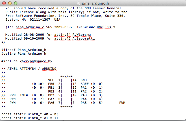
In the hardware folder of your Arduino folder is a text file called "pins_arduino.h". In this file is a diagram that shows which pins on the microcontroller correspond to the Arduino pins. It's important to note that the pins are NOT referred to with the same numbers. For example, I have the LED and button connected to pins 6 and 10 on the ATtiny, but in the Arduino programs, I had to refer to them as 3 and 7.
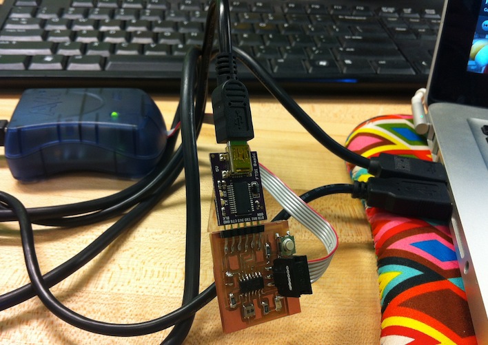
To program your board, you need to connect it to an in-system programmer (ISP). I used an AVRISP mkII, but you can also use your FabISP that was made for the electronics production assignment. Then you need to power your board using an FTDI USB cable plugged into your computer. Then, select your board and the programmer you're using under the Tools menu in the Arduino IDE. Then under the same menu, select "Burn Bootloader" which doesn't actually burn any bootloaders, but sets the fuses, i.e. sets the clock speed for the microcontroller to operate at (This is just a repurposing of a built-in menu option in the Arduino IDE, which can be misleading).
First I tried some examples provided in the Arduino IDE. I found this to be an easy way to jump into trying coding and becoming familiar with the Arduino library. I tried the blink example, which just blinks the LED using the delay function. The button example turns on the LED when the button is pressed. I combined the programs to make the LED blink when the button is pressed. I also tried the fade example. A few of the pieces of my reflex test game are based on things I learned in the example codes.