Week 6: Electronics Design
The assignment for this week was to redraw the echo hello-world board and add at least a button and LED.
Drawing the board
I used EAGLE to design and draw the PCB. First, I made a schematic where I layed out all the components that I chose from a library. This is the library we used for this assignment.
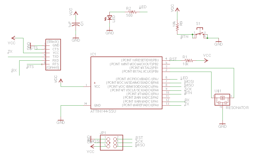
- add : this brings up all the libraries and lets you select components to add
- rotate: to rotate components
- del: to delete components
- move: to move components
- net: to make connections between components
- name: to name nets. If you name nets the same thing in your schematic, they can be connected without actually drawing a net between them. I used this for connecting components to the pins on the microcontroller.
- label: to put the name label next to the component after you have named it.
- val: to label components with their values (such as resistance, capacitance, etc.)
Then you can generate a board from your schematic. In this step, you actually have to place the components and make connections in their physical locations. The command "route" is useful for drawing connections. The command "rip" is for removing connections, and the command "drc" can be used at the end to perform a design rule check.
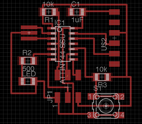
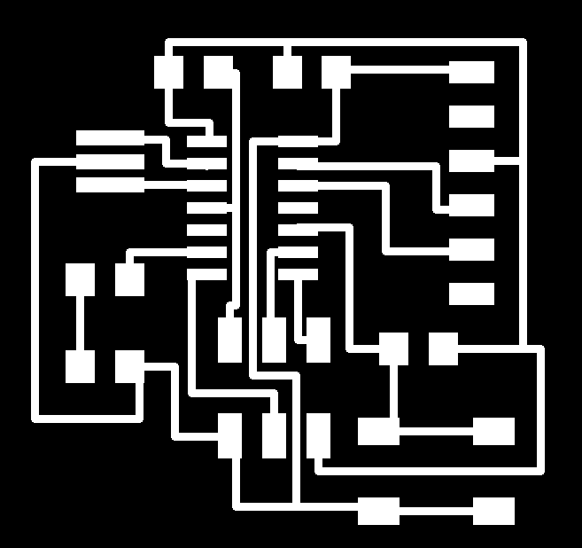
After you're satisfied with your design, you can export the board as a PNG. Then you can open it in your favorite graphics editing software to crop it and then also make an outline.
Making the board
The PNG file exported from EAGLE is used for milling the board. The 1/64" bit is used for milling the traces and the 1/32" bit is used for milling the board outline.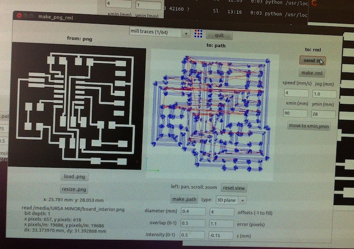
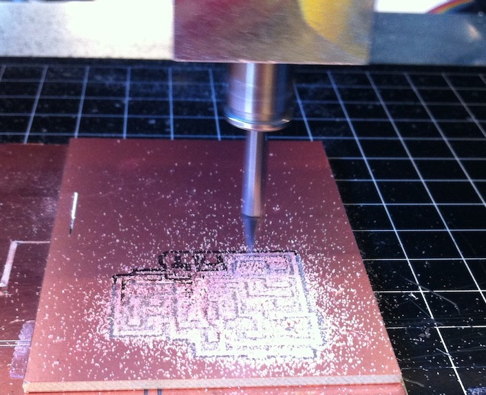
I ran into some issues with getting the bit to mill all the way through the copper layer in some parts. Here are some things I learned about milling and z-axis depth issues:
- It's important to ensure the bit is screwed in tight enough. You don't want to screw it in too tight and risk stripping the set screw threads, but you do need it tight enough so that the bit doesn't get pushed up while milling.
- The bed can be non-uniform in height. For example, I noticed the bed of the machine was slightly bowed. Because of this, it's a good idea to test your z-axis height at several locations.
- When lowering the bit with the up/down buttons on the machines, make sure the z-carriage has room to move and is not pushed all the way down.
- After setting the carriage quite low, but still leaving room for it to move down more, unscrew the bit and carefully guide it down to the surface of the material. Make sure the bit is pushed into the material as you screw it in again.
- If you need to kill a job that is running on the machine, hit the "view" button, then hit the up and down buttons simultaneously until the green light blinks. Then go into the terminal and type "ps -aux | grep cat". Then type "kill ____" where ____ is the number that corresponds to the job that is running.
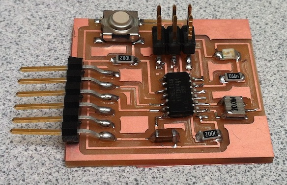
After milling, I soldered on all the components. Here is the finished board!