Networking and Communication
This week our task is to design and build a wired &/or wireless network. I have tried two ways: Serial and ESP9266 wifi module
PySerial
In order to let python talk to my board over a serial interface, the first thing to do is to install the library pySerial. Then I noticed that it mentioned that the example "will not work on a Windows machine". But after some searching, I think we can just ignore it.I installed pySerial through Andconda but it does not work after the installation.
Here is the bug:
SerialException: could not open port '/dev/tty.usbserial': WindowsError(3, 'The system cannot find the path specified.')
I wasted a lot of time in searching for the proper address for COM6... Turns out that I was overthinking and it's just 'COM6'.
I ran the sample code copied from the Arduino Playground:
import serial
ser = serial.Serial('COM6', 9600)
ser.write('5')
Nothing happened in python (of course), so I opened the serial monitor in Arduino IDE, then the Arduino give me this error report: "Error opening serial port 'COM6'. (Port busy)". After that I kept failing to run the same code, so I restarted my laptop.
Finally, succeeded in reading Arduino data in python by following this tutorial
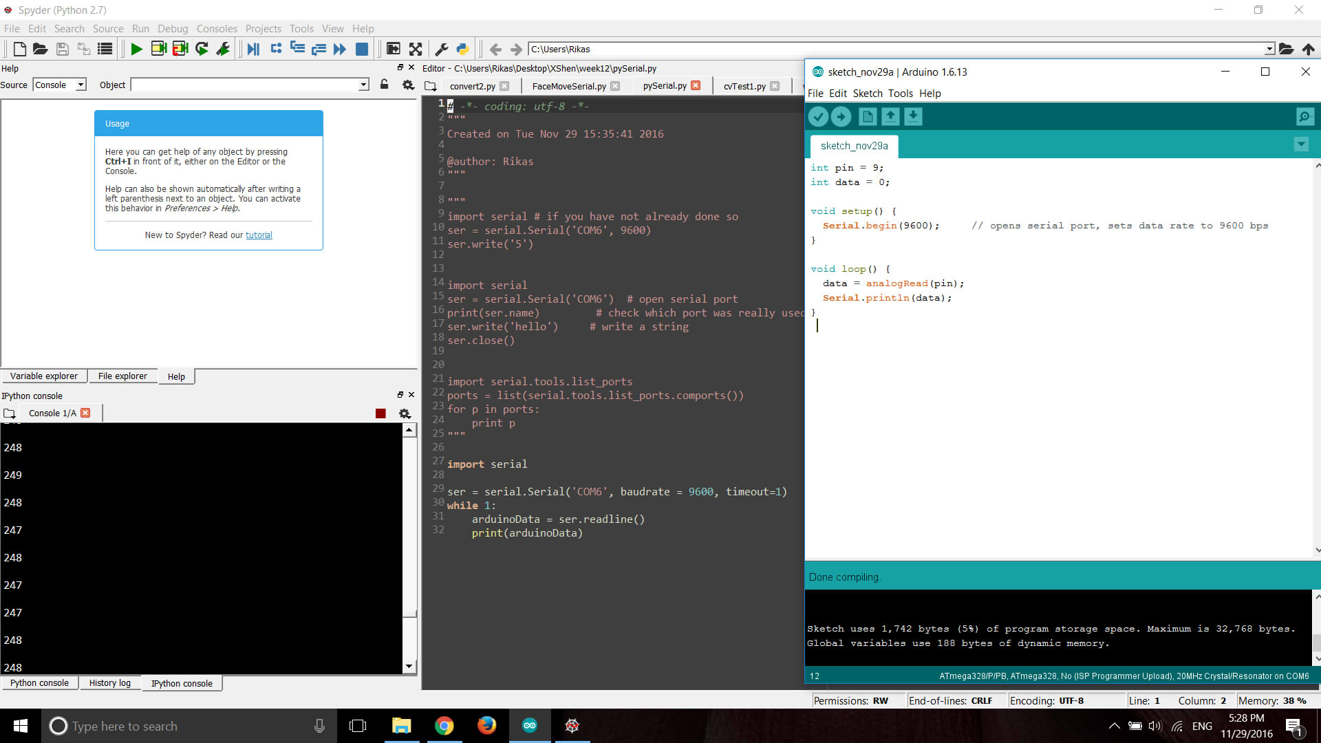
Then I made another test on sending signal from python (trigger the board to read signal when letter 'g' is typed) to the board and then get the data back to python.
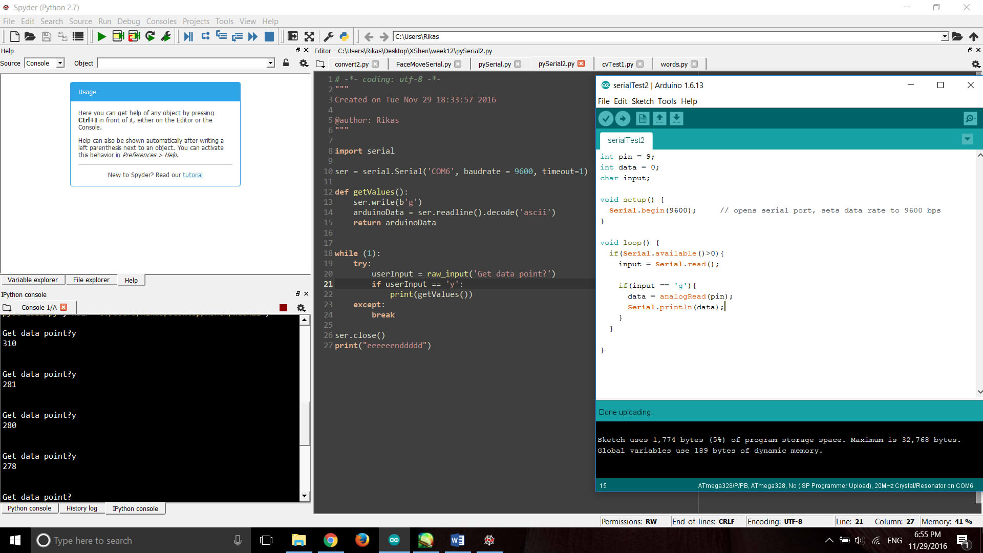
Since there's no proper way to stop the communication in this case so I used ctrl+C to stop the kernel in python. Then I added a count number in Arduino to ask it to end the serial after, for example, 30 counts. However, the "access denied" error came out again when I try to run the python code. I guess it's due to my improper way to shut down the python script and the serial port is thus still occupied. Then I close and reboot Spyder.
Next step is to send the data of face position to Arduino in order to control the motor or create a simple interface in Processing. But it suddenly came up with the error which I have never met before:
File "C:/Users/Rikas/Desktop/XShen/week9/FaceDetectionMove.py", line 18, in
gray = cv2.cvtColor(frame, cv2.COLOR_BGR2GRAY)
error: ..\..\..\modules\imgproc\src\color.cpp:7456: error: (-215) scn == 3 || scn == 4 in function cv::ipp_cvtColor
The error occurs even when I turned back to the old version with just face detection function. I have no idea what's happeninng and it is already Tuesday night now… So I could not finish this week's task on time. I will keep working on it and try figuring out what goes wrong. Here is an additional tutorial I found may useful.
Update Dec 10:
Continue from the old problem I have left.
The error message seems to say that my img is not loaded properly. So I typed "print img.shape" under the imread line in order to check whether the img is loaded properly. Turned out it printed (1080L,1920L,3L) so the image has no problem. The next step I did the dumbest but also one of the most useful ways when you have no idea what's going wrong --- add pirnt under every single step. And finally it was discovered that the problem is "ser.write(x)". I edited the exception to
except Exception, e:
print e
The printed error says:
'numpy.int32' object is not iterable
Ta-da! Type error it is! So I converted x to a string and tested, no error this time! I also
attached an LED to the board to see if there's anything sent to the port, and it works! Great, finally
I've solved this "trivial" problem that bothered me so long time and I can keep struggling in the next "trivial" problem. Next step is to change the single image to real time capture of face detection. Everything works well so far and the signal is transferring through pySerial. Then I change the led output from digitalWrite to analogWrite, trying to change the lightness of the led with the position of my face. But it did not work, there is light but it did not change as I expected. According to the pySerial documentation, it is because (that the strings are in Unicode so they have to be converted to bytes.(or ASCII not sure) I found a tutorial doing the face detection and face tracking using Arduino and OpenCV through pySerial. This one is useful in his way tranferring number from pyserial to the value that the board could read.
Further work on controling the servo motor with face position data sent through serial will be updated in final project page.
Test on ESP8266 wifi module
I have also tried out the ESP8266 wifi module since I wanted to see the possibility of making the robot wireless someday.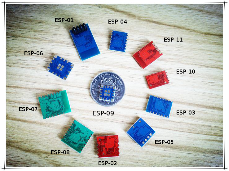
The ESP8266 WiFi Module is a self contained SOC with integrated TCP/IP protocol stack that can give any microcontroller access to your WiFi network. The ESP8266 is capable of either hosting an application or offloading all Wi-Fi networking functions from another application processor. Each ESP8266 module comes pre-programmed with an AT command set firmware. The ESP8266 is a huge family with various types of modules, they are confusing and take some time to figure the fact out when it is the first time for you to get in touch with these modules. the one I am using is ESP8266-01.
Due to the datasheet, I see a power supply of 3.3v is needed. And it was suggested to get a voltage control board-but we can
1. build a voltage control by myself.
2.use a power supply to test on breadboard.
After wasting a lot of time researching for the power regulators. I suddenly found out that the FTDI I bought have voltage changer itself! I realized that fact since a website I was looking at saying there is a bug for current FTDI and hope it will be fixed and it's an old post. so I just checked on my FTDI with a multimeter. Do not be cheated!! It has wasted me so much time!!
Following this to wire the ESP8266, This is a great instruction to start with the module: http://rancidbacon.com/files/kiwicon8/ESP8266_WiFi_Module_Quick_Start_Guide_v_1.0.4.pdf
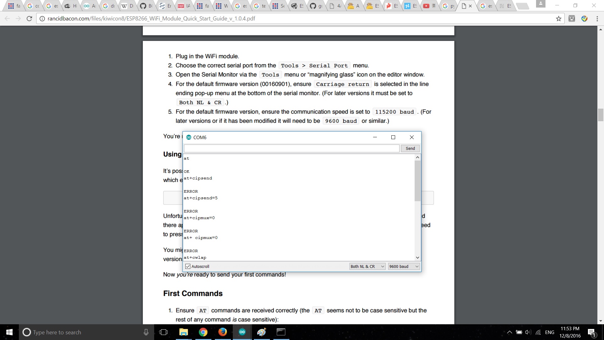
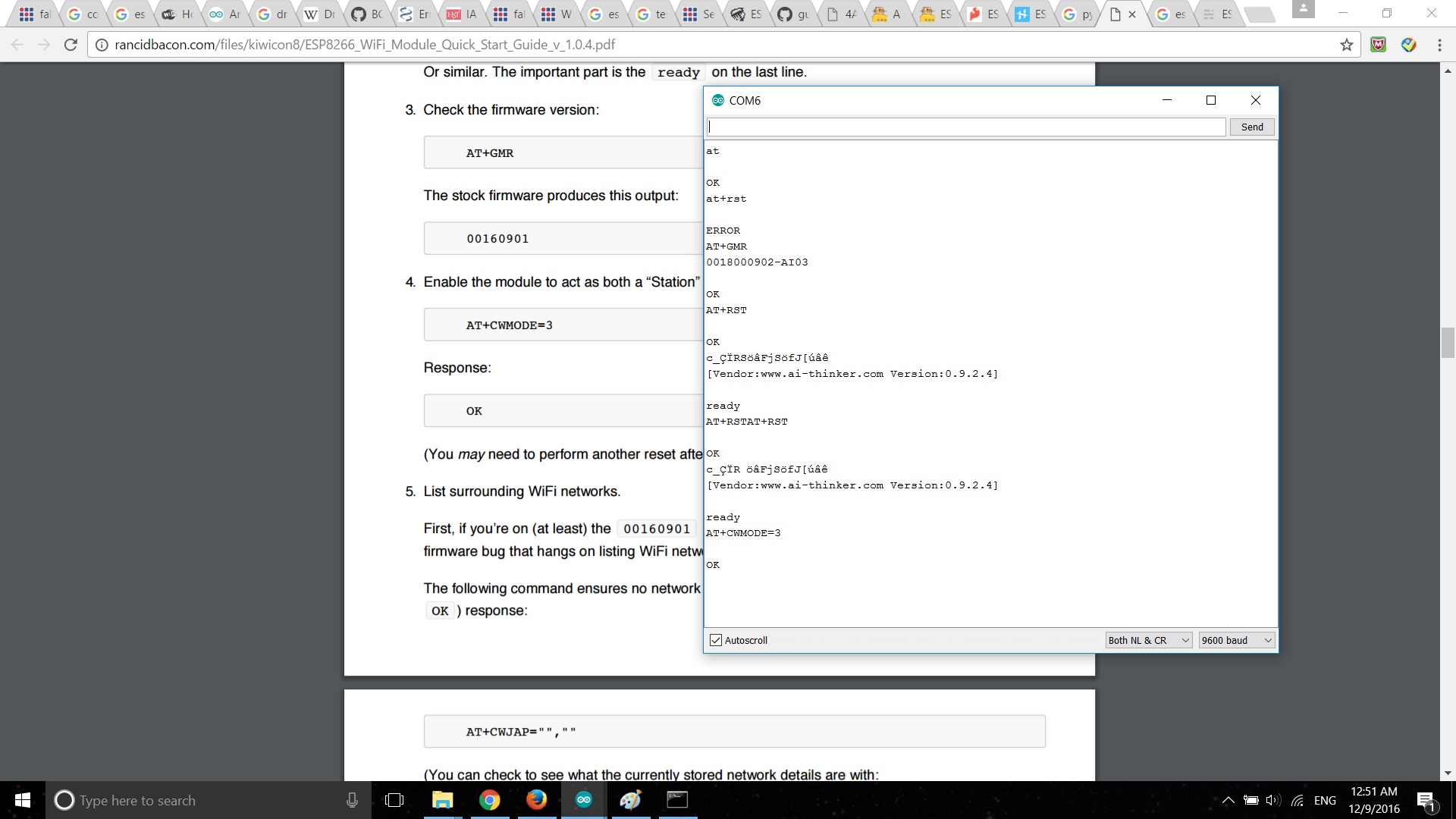
Sometimes you might get ERROR or no response-in which case you'll have to try doing the USB plug/unplug cycle and try again. (Or the same with the ground jumper.)
Then I start to test it with AT commands:
-	Act as a TCP server
AT+CIPMUX=1
OK
AT+CIPSERVER=1,80
OK
AT+CIFSR
192.168.4.1
0.0.0.0

OK
Then I try to link the wifi module with Arduino and let them do the next step as this tutorial:
But it has a problem to talk to upload the board and no respond to AT commands.
Then I noticed the board was hot. Used the multimeter to test - RX pin from Arduino board is also 5v. it's easy to be neglected but need to be aware of, otherwise there will be chance to do damage to the wifi module. We can use resistors in series to separate voltage in this case.
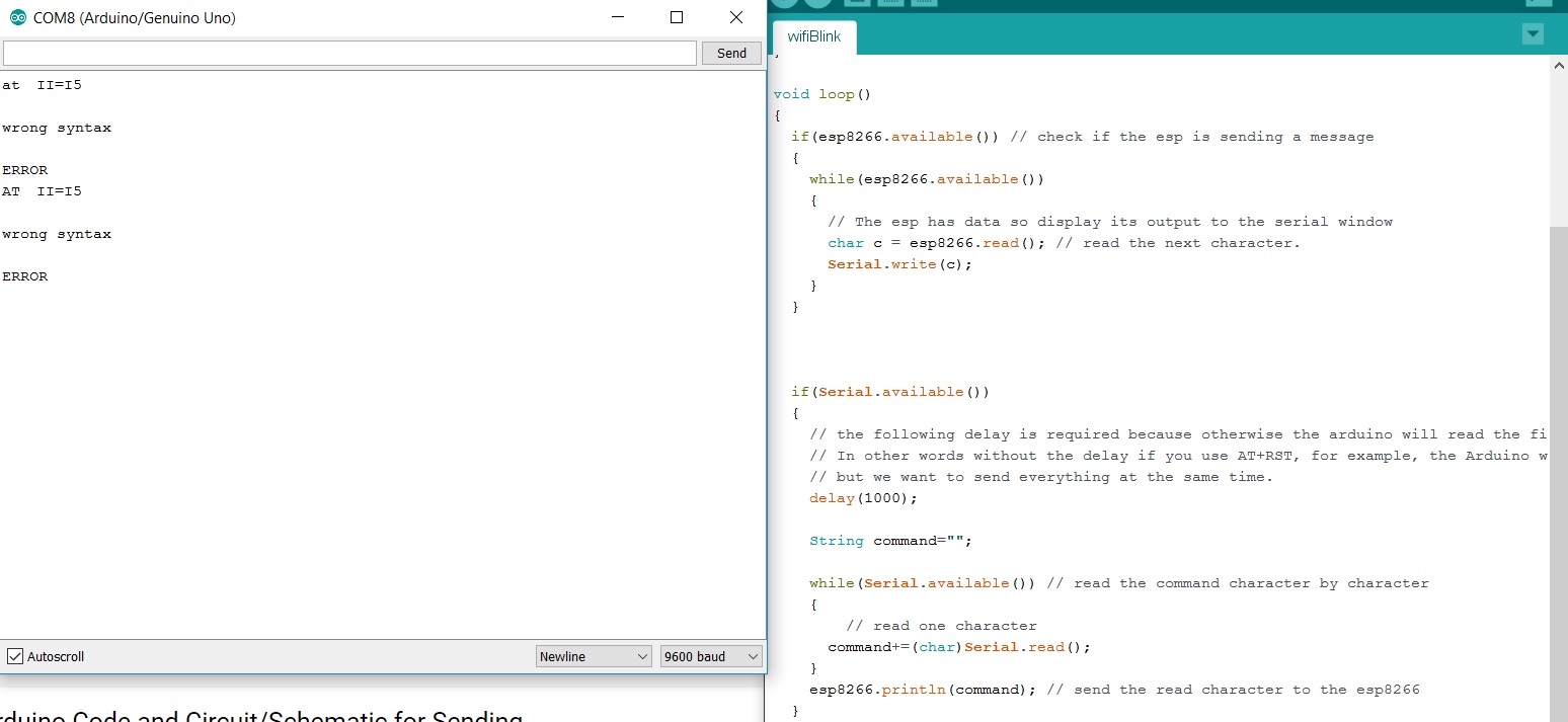
But still, everytime when I type "AT" or any other commands in serial port there always will be a "II=I5" and then a Syntax Error result is reported back…
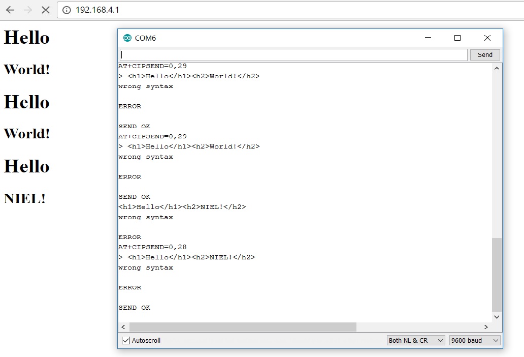
Later I changed back to wire to FTDI. Managed to send hello world command to its ip address.
Files
Test 1: read data from board and send to iPython console
Serial Test 1 Arduino file
Serial Test 1 Python file
Test 2: send data from python to the board and trigger the data reading
Serial Test 2 Arduino file
Serial Test 2 Python file