Final Project
My final project plan is to create a robotic arm that can follow the position of the face
and then do some task such as slapping the face (just kidding... or am I >:3?).
Skill intergrated for making this project
3D modeling/Computer Aided DesignLaser cutting
Electronic design & production
3D printing
Casting
Input Devices
Output Devices
Interface Programming
Networking and communication
Sewing
Robotic Arm Design
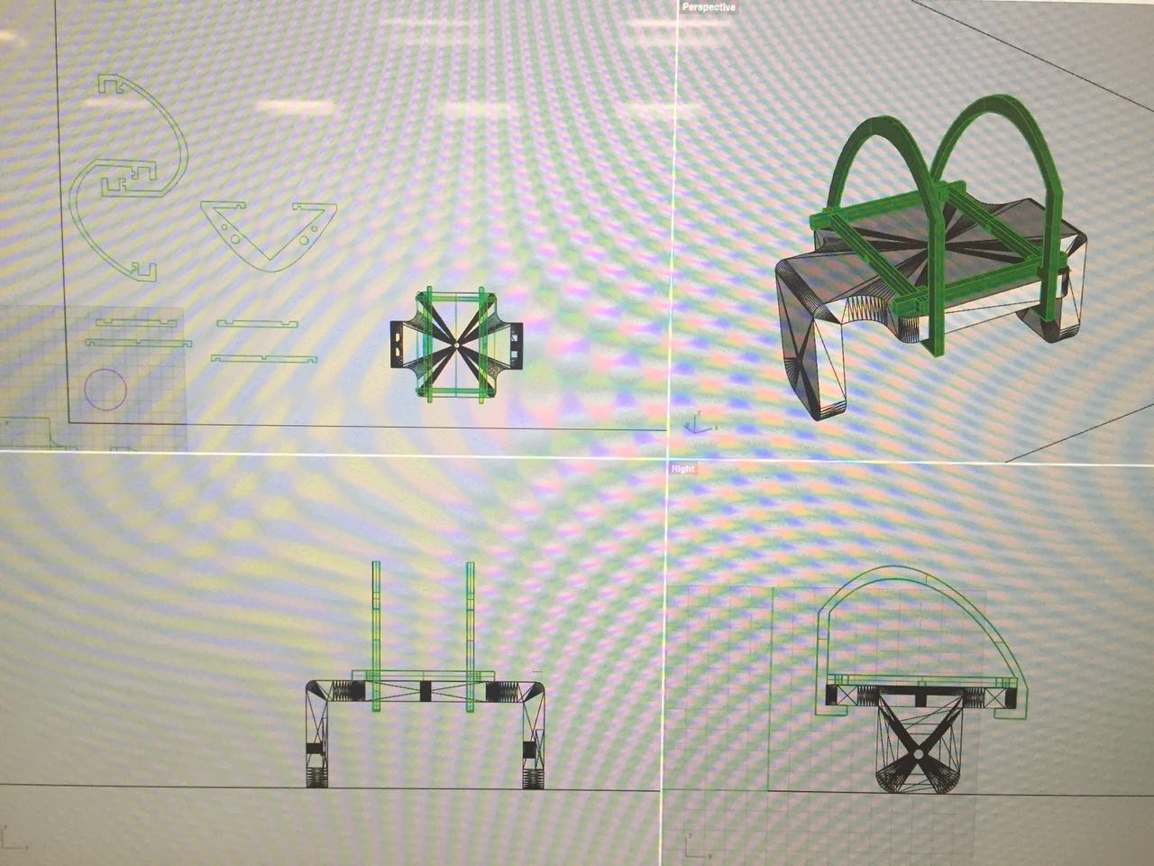
The initial design of the arm was created in week 6 CNC Machining week. It's a really big prototype (since that week is asking us to "make something big"), but the final work would be much smaller considering of the feasibility and (most important) price of the material. Later I found that a previous student (Dan Sawada) has also made a robotic arm which is very close to what I want, so I decide to use his model and do modification based on that.
Change to Pan & Tilt Design
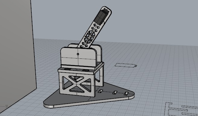
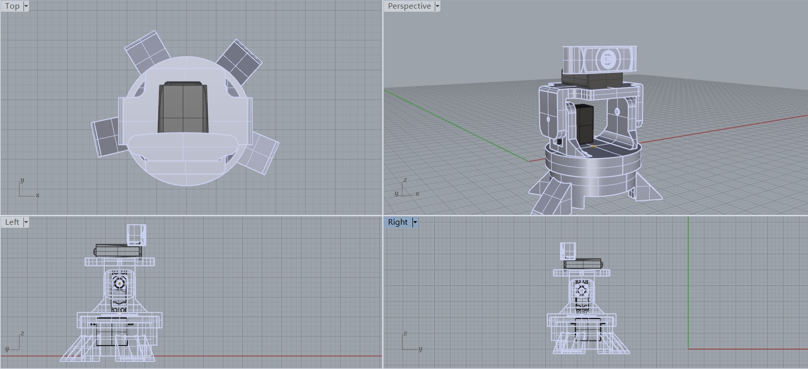
Since I've been stuck with the electronic and software part for days and many other reasons, I decided to change the design to a pan & tilt structure instead of the robotic arm.
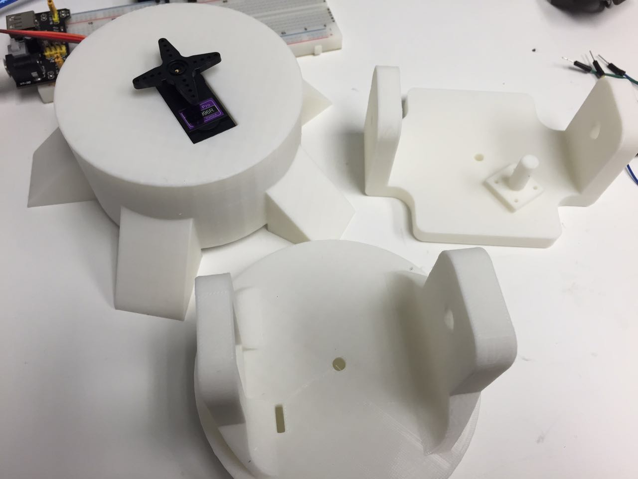 Then I 3D printed the parts out using WOX. WOX is great, it is the most reliable printer type.
No molding but casting
When I try to assemble the servo motor and pan and tilt part I found that the brush is not perfectly fit, which makes the structure shacky while working. This may also cause the problem of face location detection data, so need to find someway to fix it.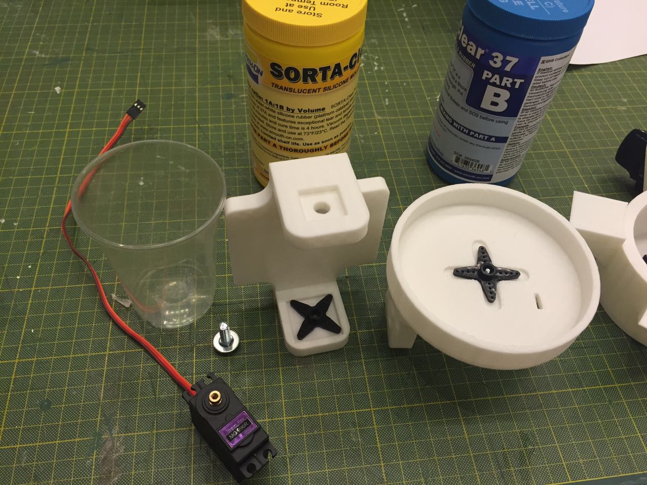
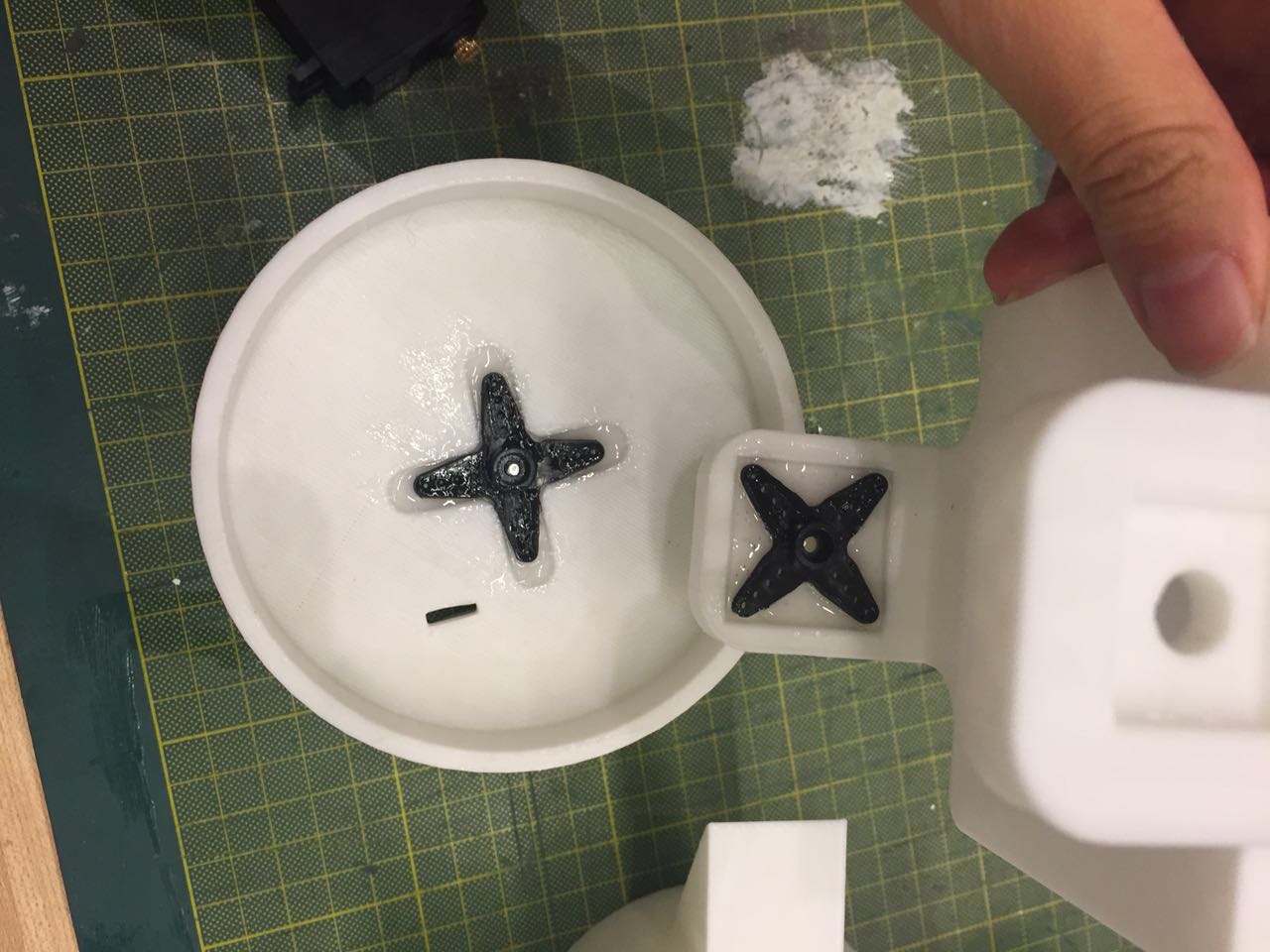
3D printing another set is definitely not the choice due to the time limitation and it is kind of wasting materials. So I suddenly came up with the idea of making use of what I have learnd in molding and casting week. The 3D printed parts and brush is the mold, I just need to cast oomoo or sillicon and the problem can be solved. I found some leftover soft silicon in the shop and did the casting slowly and carefully.
This takes much less time, cost much less, and the holder is "stylized" so it worked really great.
Laser cutting
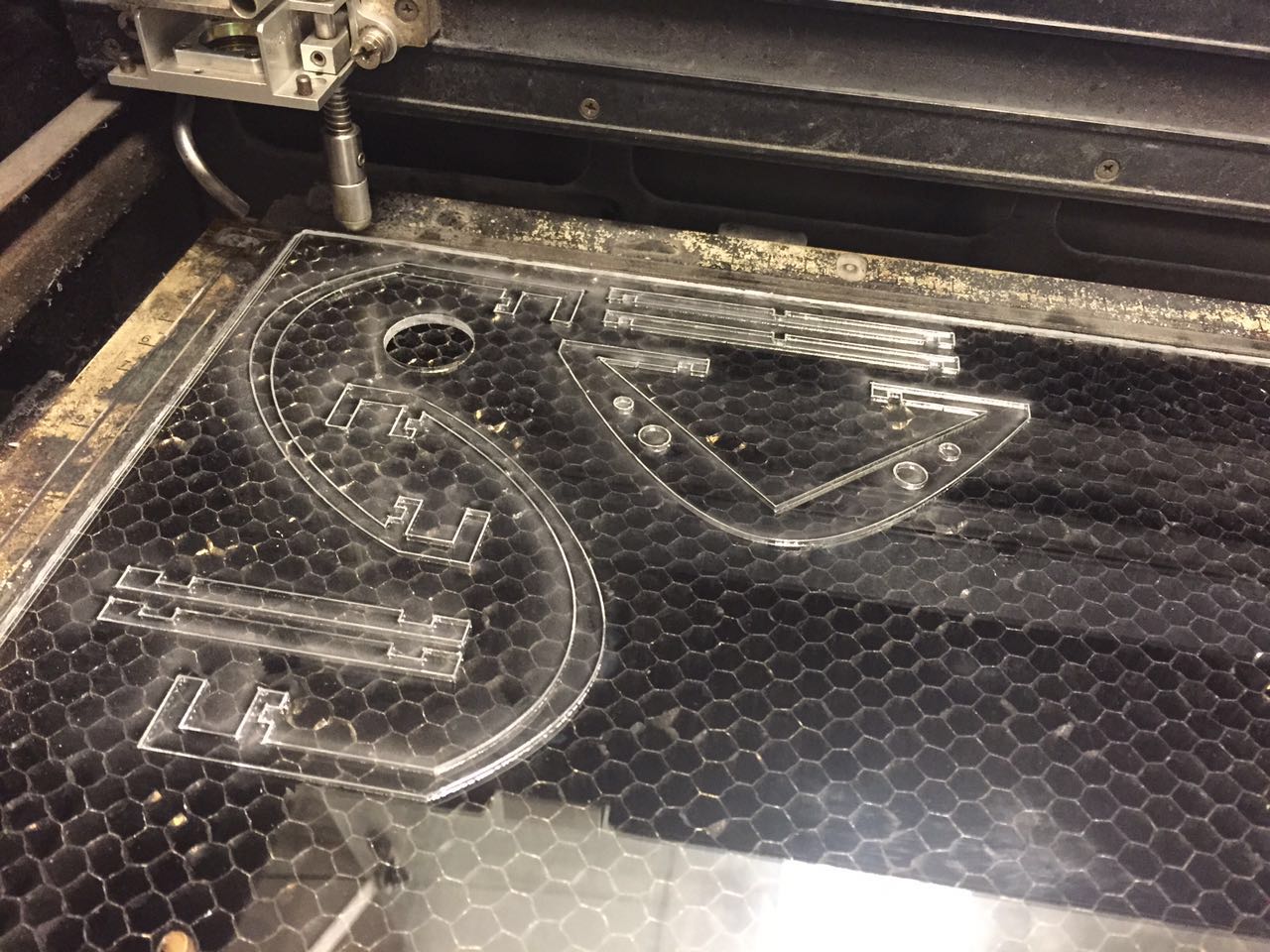
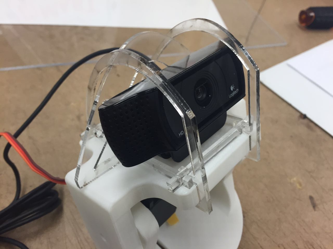
Made a press-fit frame on top of the structure using laser cutted 1/8" clear acrylic.
I almost forgot how to use the laser cutter after so long time not using it.
Face Detection
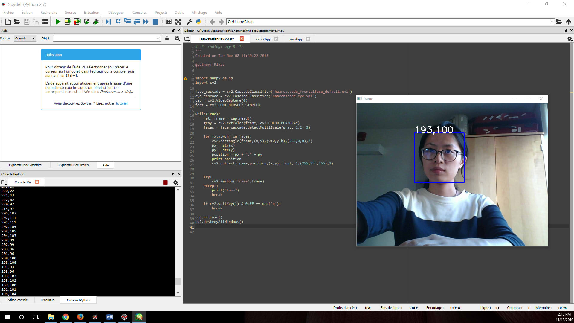
I decided to use the python with openCV library to do the face detection. For more details please see the week 9 Input Device page.
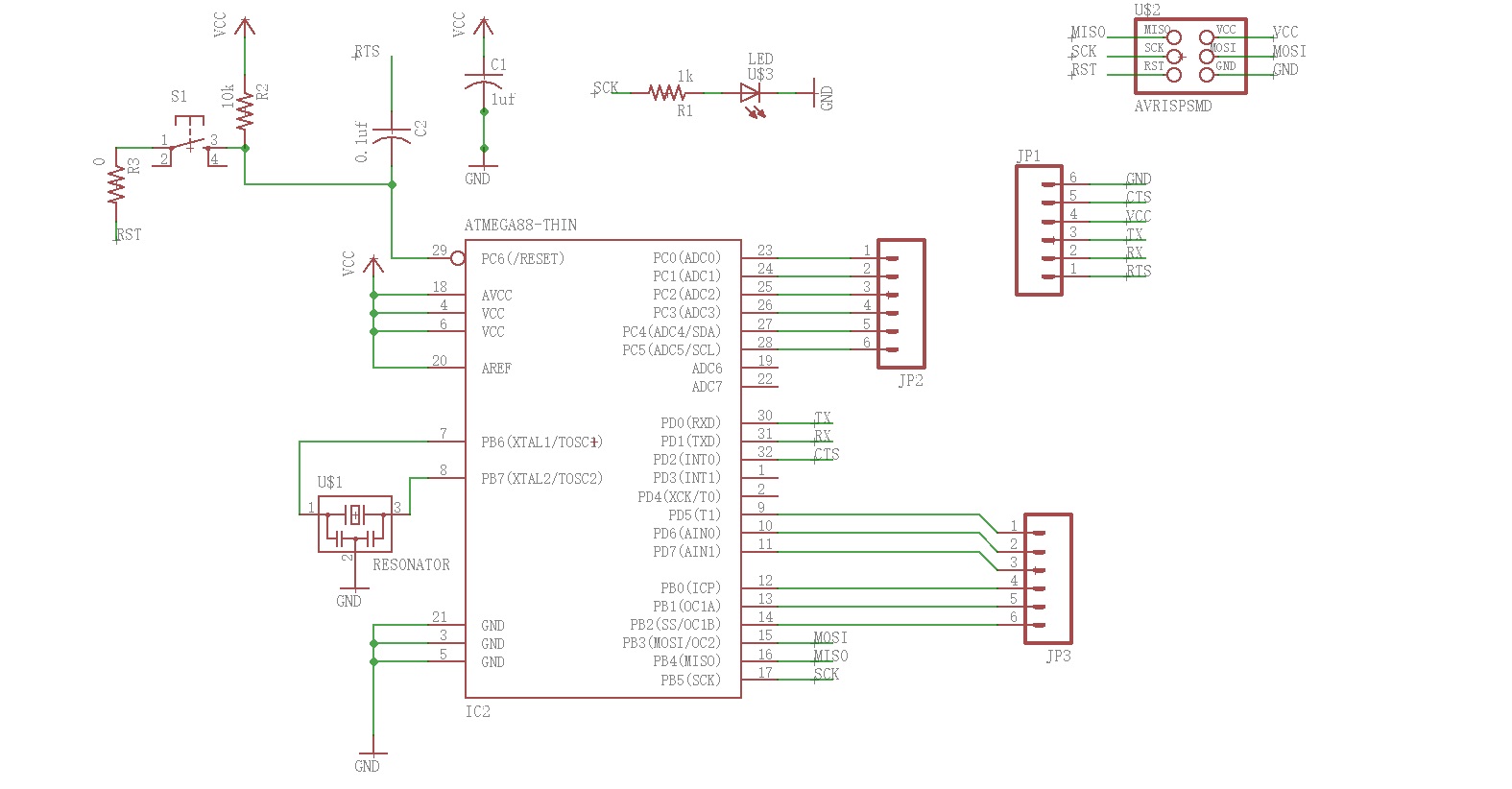
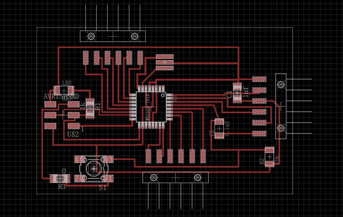
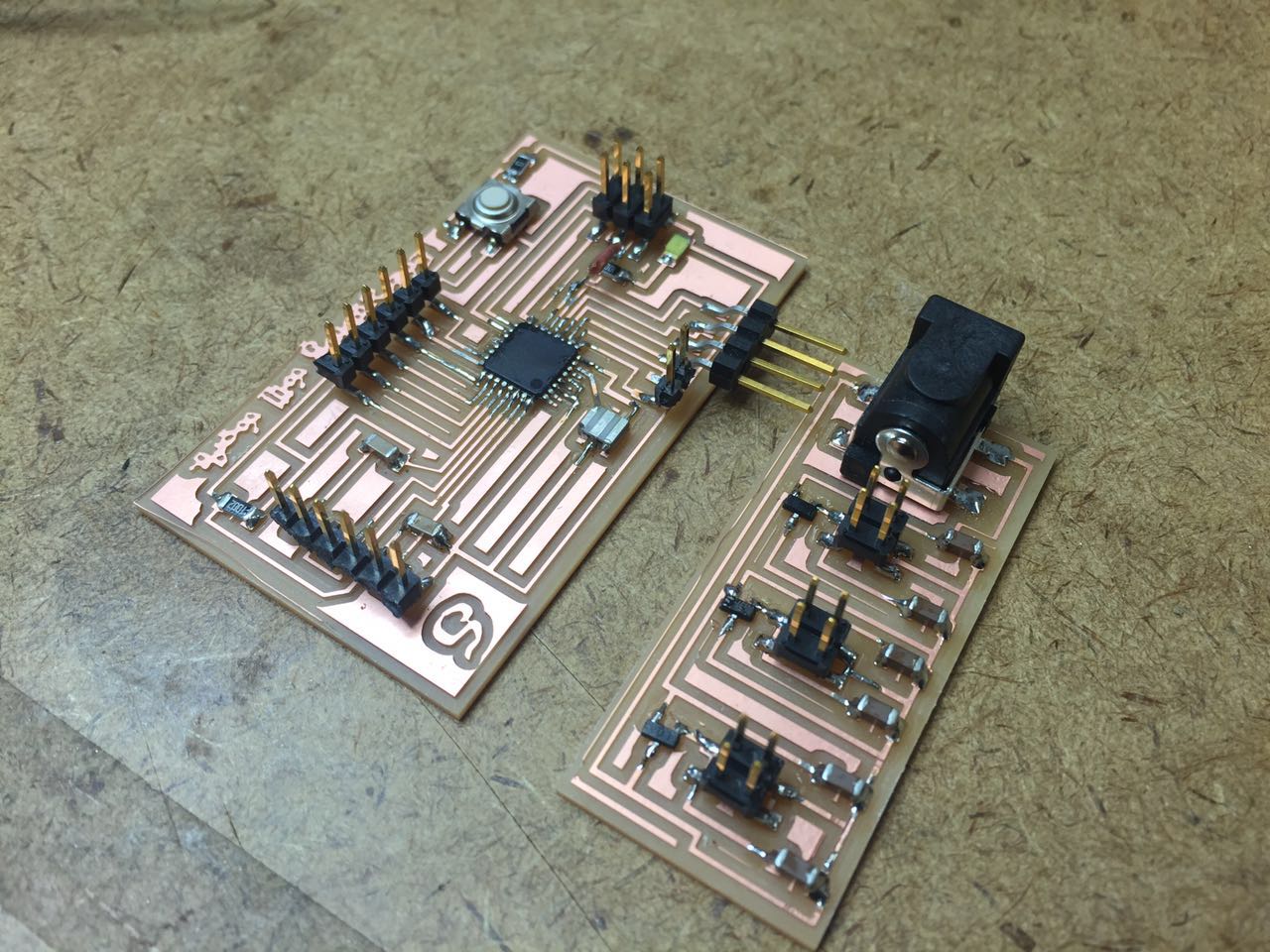
Circuits Design & Board Making
I am doing the testing on an Arduino Uno board I have so far. I wanted to mill and made my own hello Arduino today (13th Dec) so I went to the shop, only to find that all 1/64" endmills are broken and Jenn said there are no more stock currently. So… hope it will be restocked soon otherwise there I could not make my own fabduino (microcontroller board) and power regulator!
Motor Test
In week 11 Output Device week , board for controlling DC motor was tested.But later I decided to change to use servo motor to realize my final project. They servo I am using is MG996R -- a type of hobby servo with relatively high speed and high torque, metal reared, and comparatively cheap.
OpenCV -> Motor
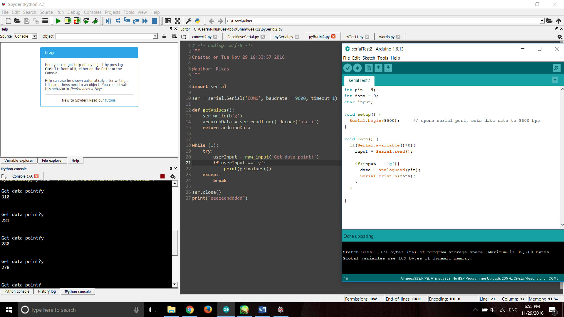
During week 13 Networking and Communication, I managed to communicate python with Arduino through serial and still trying to use the data detected by openCV to control the motor...
Update Dec 10:
Continue from the old problem I have left.
The error message seems to say that my img is not loaded properly. So I typed "print img.shape" under the imread line in order to check whether the img is loaded properly. Turned out it printed (1080L,1920L,3L) so the image has no problem. The next step I did the dumbest but also one of the most useful ways when you have no idea what's going wrong --- add pirnt under every single step. And finally it was discovered that the problem is "ser.write(x)". I edited the exception to
except Exception, e:
print e
The printed error shows:
'numpy.int32' object is not iterable
type 'exceptions.TypeError'
Ta-da! Type error it is! So I converted x to a string and tested, no error this time! I also attached an LED to the board to see if there's anything sent to the port, and it works! Great, finally I've solved this "trivial" problem that bothered me so long time and I can keep struggling in the next "trivial" problem.
Next step is to change the single image to real time capture of face detection. Everything works well so far and the signal is transferring through pySerial. Then I change the led output from digitalWrite to analogWrite, trying to change the lightness of the led with the position of my face. But it did not work, there is light but it did not change as I expected. According to the pySerial documentation, it is because (that the strings are in Unicode so they have to be converted to bytes.)(or ASCII not sure) I found a nice tutorial doing the face detection and face tracking using Arduino and OpenCV through pySerial.
I modified my Arduino code based on this instruction and mapped the reading of x position to the 0-180 degree of the servo motor.
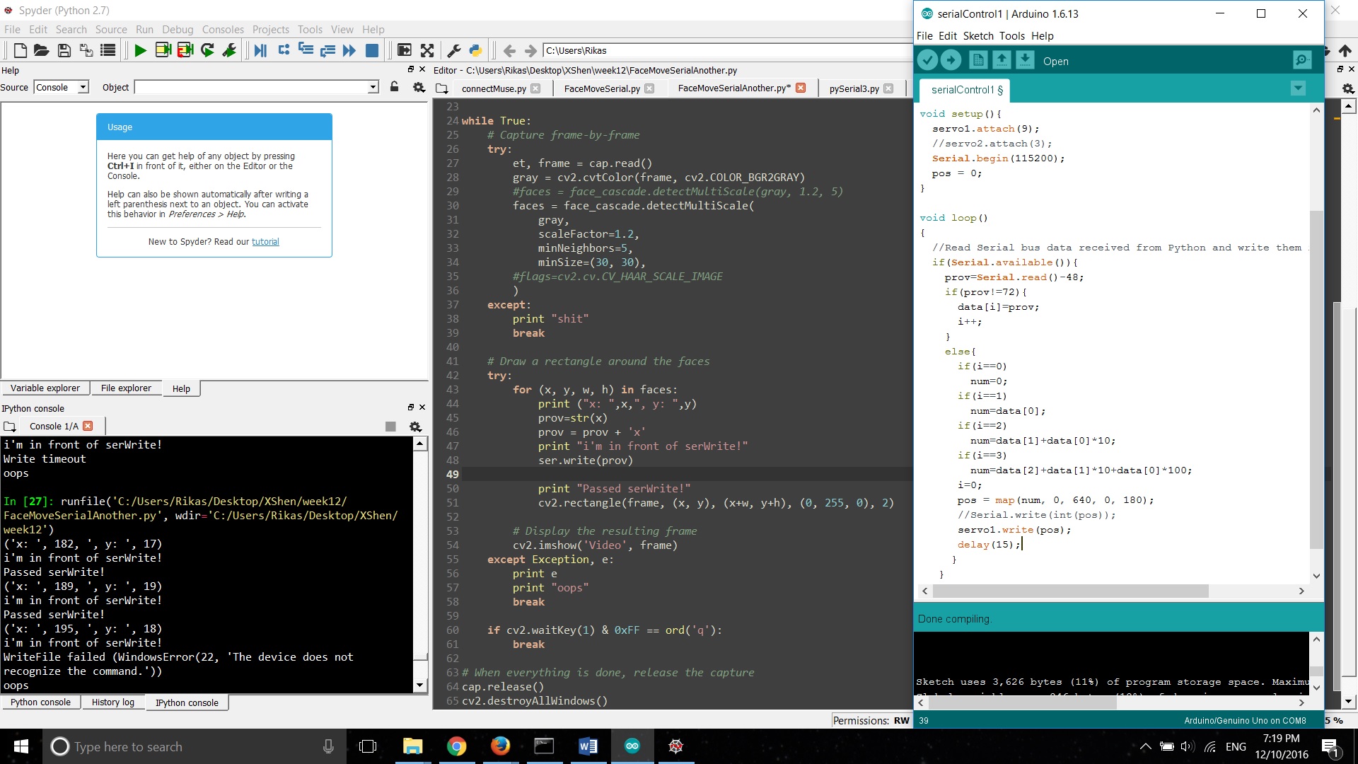 But the problem I meet this time is that it only works for a short time and then come up with error with in only 3 frames.
It runs good when I detach the servo, the problem occur only when the servo is linked. I add the exception again and the
error message is :" WriteFile failed (WindowsError(22, 'The device does not recognize the command.'))" …. I have no idea how
to solve this so I sent an inquiry email to the TAs.
But the problem I meet this time is that it only works for a short time and then come up with error with in only 3 frames.
It runs good when I detach the servo, the problem occur only when the servo is linked. I add the exception again and the
error message is :" WriteFile failed (WindowsError(22, 'The device does not recognize the command.'))" …. I have no idea how
to solve this so I sent an inquiry email to the TAs.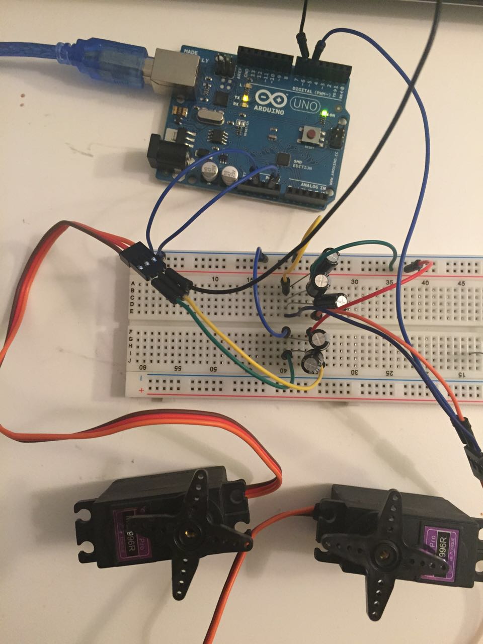
 According to Eric's reply it may mean that the power supply is crashing when the servo loads it.
Since I am using the Arduino board's 5v DC supply to test the servo so I just try to add capacitors to see how it goes.
This webpage
suggest a 470uF or greater capacitor but I only have several 100 & 220 uF capacitors in my hand. I tried them out first,
the 100uF capacitor does not work, the power supply still crash quickly. But when I change to a 220uF one things get better:
the servo is behaving weirdly but the OpenCV window stops crashing and the data can keep send to the board.
So I put the capacitors I have together and maintained a 540 uF capacitance.
Now I need to figure out the problem of the data sent through serial and why the servo seems so uncontrolled.
According to Eric's reply it may mean that the power supply is crashing when the servo loads it.
Since I am using the Arduino board's 5v DC supply to test the servo so I just try to add capacitors to see how it goes.
This webpage
suggest a 470uF or greater capacitor but I only have several 100 & 220 uF capacitors in my hand. I tried them out first,
the 100uF capacitor does not work, the power supply still crash quickly. But when I change to a 220uF one things get better:
the servo is behaving weirdly but the OpenCV window stops crashing and the data can keep send to the board.
So I put the capacitors I have together and maintained a 540 uF capacitance.
Now I need to figure out the problem of the data sent through serial and why the servo seems so uncontrolled....Then I don't know what I have done but it suddenly worked.
Eric disagrees with the page giving the advice of add a capacitor to solve the misbehaviour of the servo. He said I can use a capacitor like that, but it's using the wrong tool for the job. Also, it technically violates the USB spec (see table 1 http://www.ti.com/lit/an/slyt118/slyt118.pdf), but darn near everything violates the power portion of the USB spec.
Btw I wanted to mill and made my own hello Arduino today (13th Dec) so I went to the shop, only to find that all 1/64" endmills are broken and Jenn said there are no more stock currently. So… hope it will be restocked soon otherwise there I could not make my own board and power regulator!
Power Supply to the servo motor
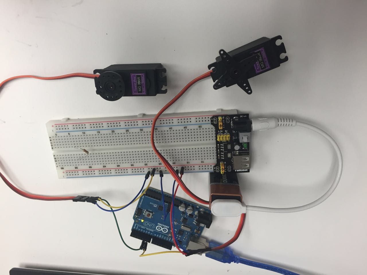
There is one big trap which caused me struggled with the servo motors for a very very long time -- the power supply.Unexpected problem happens every now and then: one servo suddenly stops working, then it suddenly works again; servo motors collapse when I try to attach two of them while one servo works well; sometimes the motor won't resume quickly after it collapse, it takes a while to wait for it to function again; it has weird sound when I just wire everything up https://youtu.be/T3rV8qI_VrQ before sending the data, etc.
Here is one of the most typical Failures: one servo attached, works okay; same code, two servos, fail.
It took me a whole week to deal with the problem which should not be that complicated: it is the problem of power supply.
So one suggestion: if your servo motors are not working well, check your power supply first.
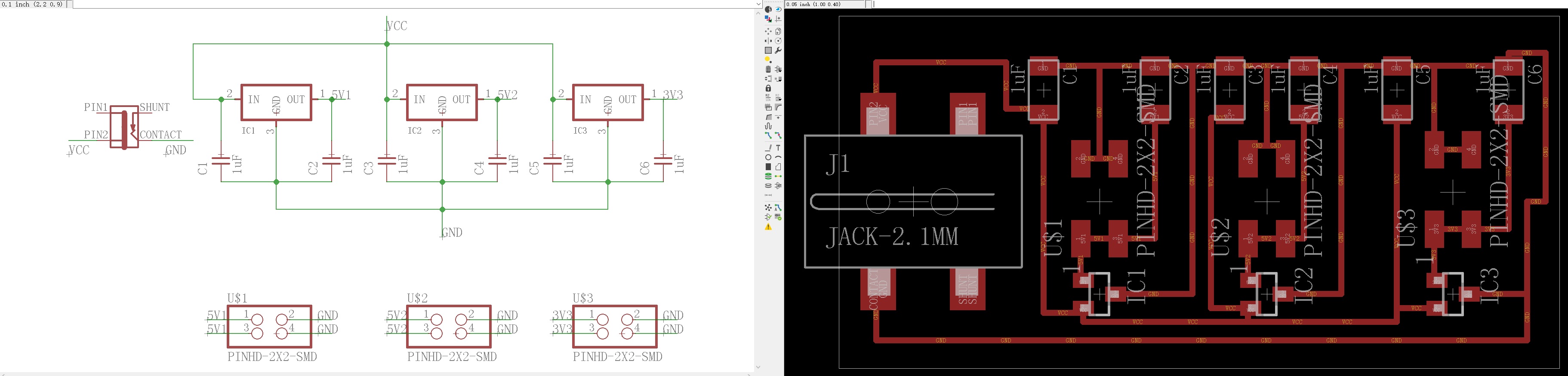
At first since I was using Uno to do the test so I just take the 5v power from the board, which would be the worst choice to run a servo. It may cause problem (such as shutting down the board and cause the software crash) even when you just use it to drive one servo motor. Later I attached an external power supply - a 9V battery. According to the datasheet of MG996R it's working voltage is 4.8 - 7.2v. So I made a voltage regulator board to protect the motor.
 But 9V battery only works well for 1 servo. If running two or more servos there won't be enough currents for them.
Thus a pack of 4 AA batteries should be the better choice.
But 9V battery only works well for 1 servo. If running two or more servos there won't be enough currents for them.
Thus a pack of 4 AA batteries should be the better choice.But what I am using now is an AC to DC power supply cable that a friend has lent to me. And it works well.
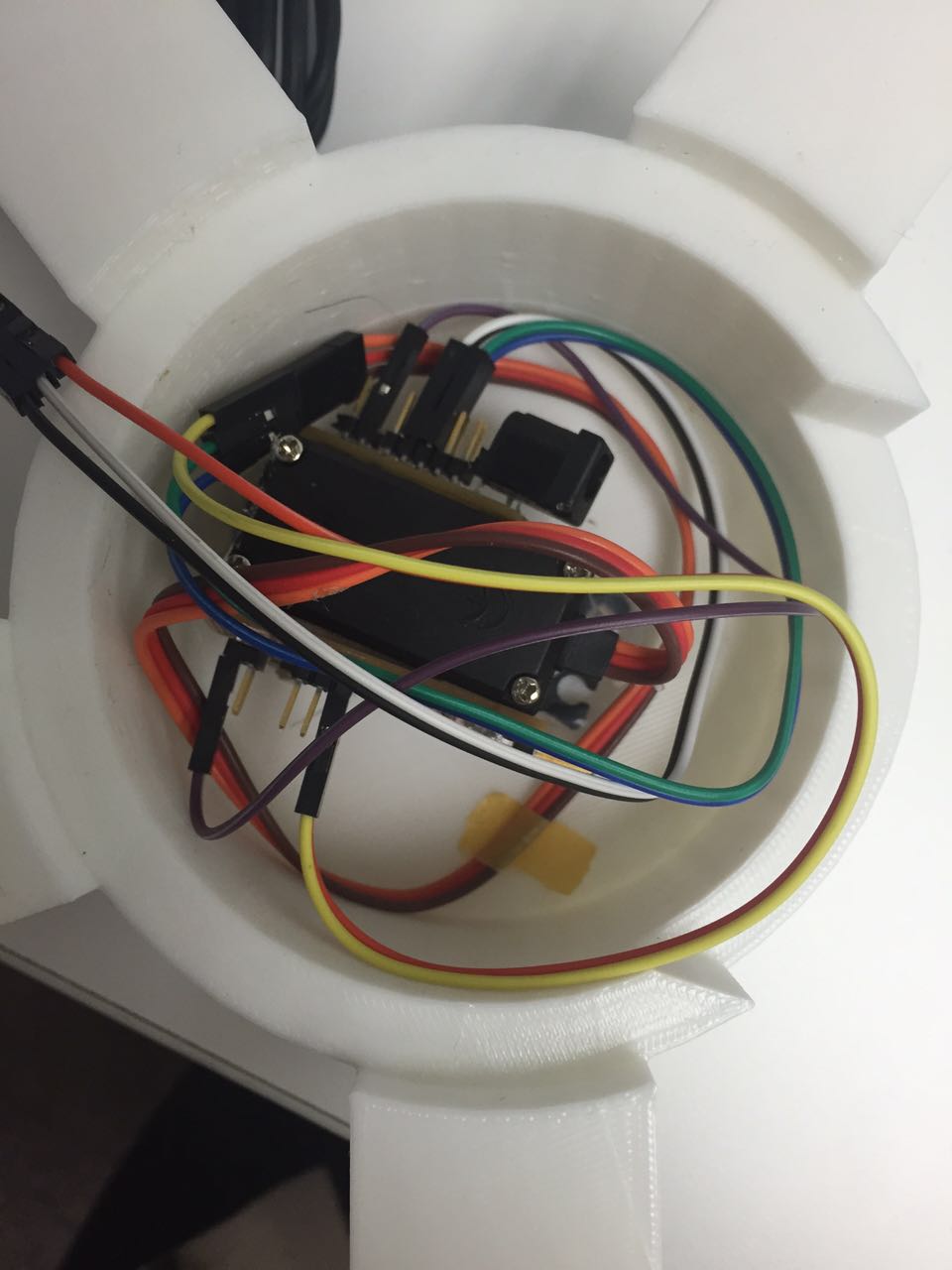
Finally I reduced the size of the power regulator board and turned back to use the ATMega328 board I have made in previous weeks, sothat I could stuff all the lines and components under the base of the pan part.
Embedded programming
After solving the power supply problem, the last step is to modify the code to control the servo and make it work without jittering. I did a lot of test and modification and it finally successed!
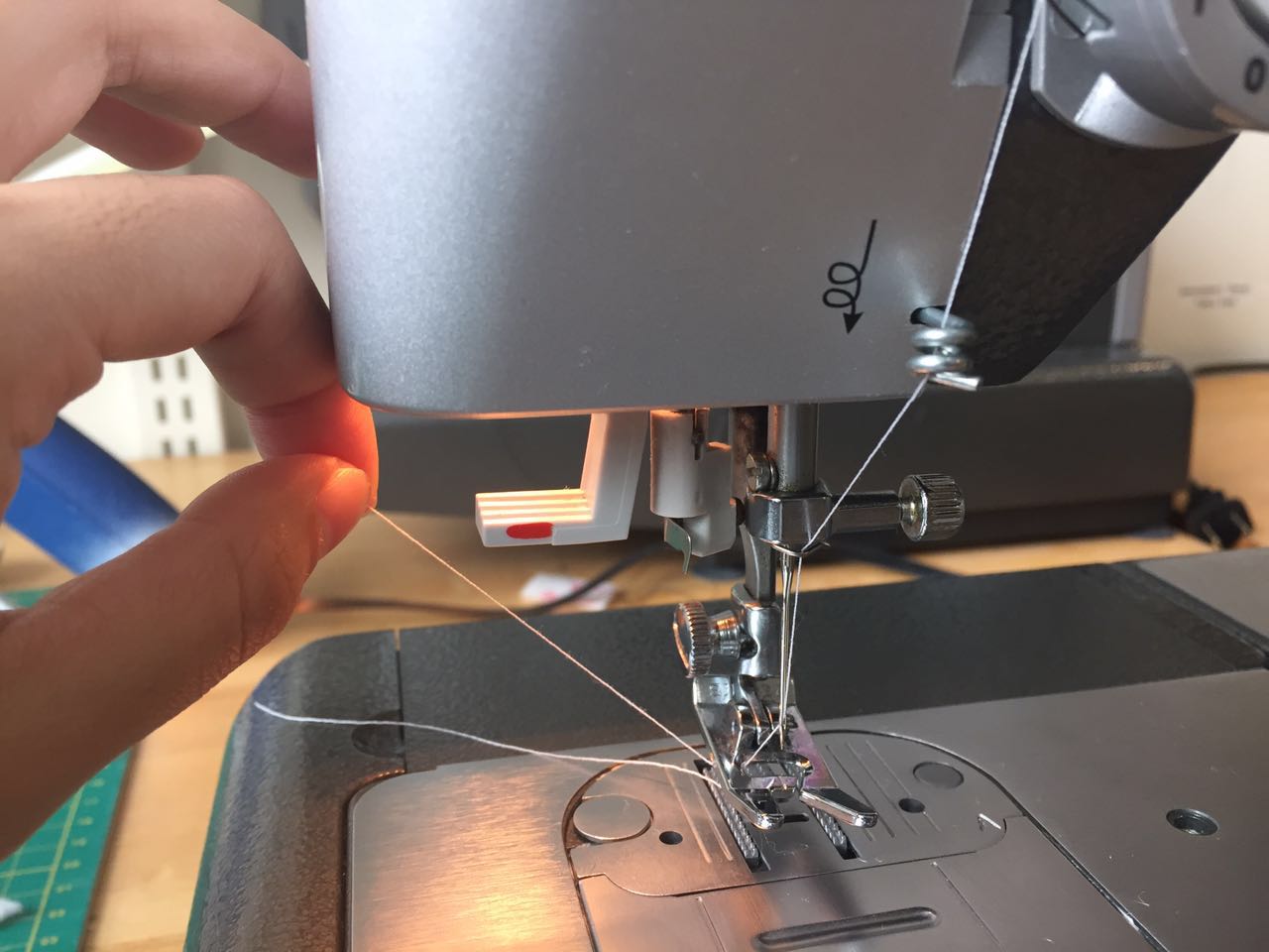
Sewing
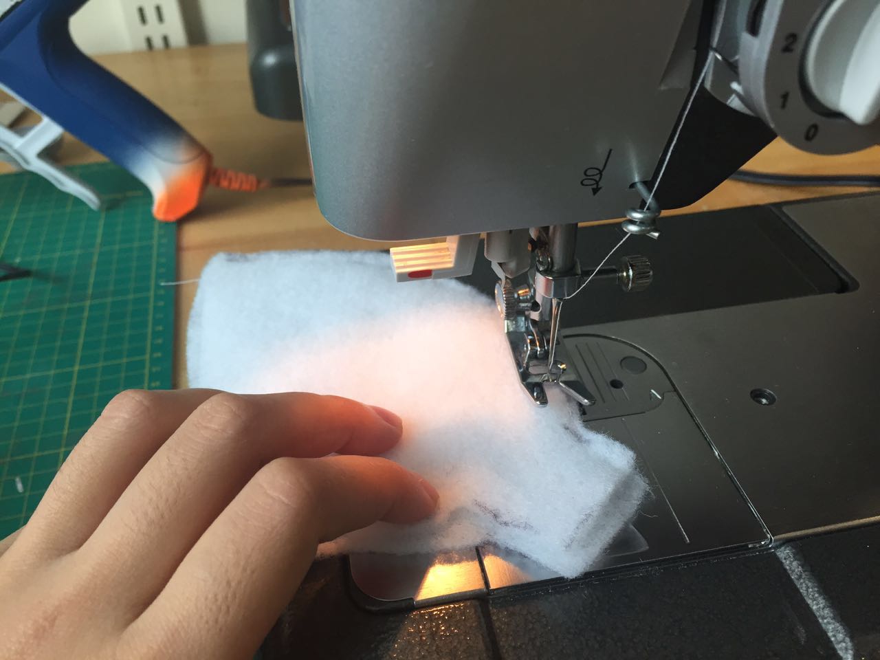
Just in the morning of our final presentation day. I let a friend to try it and he said "Wow it's kind of creepy when it keeps staring at you lol." Then I suddenly got the idea of "okay why not I just make it creeper?"
I rush into the sewing shop and rapidly made a costume of a little ghost. It is really rough, could have done it better if I had more time.
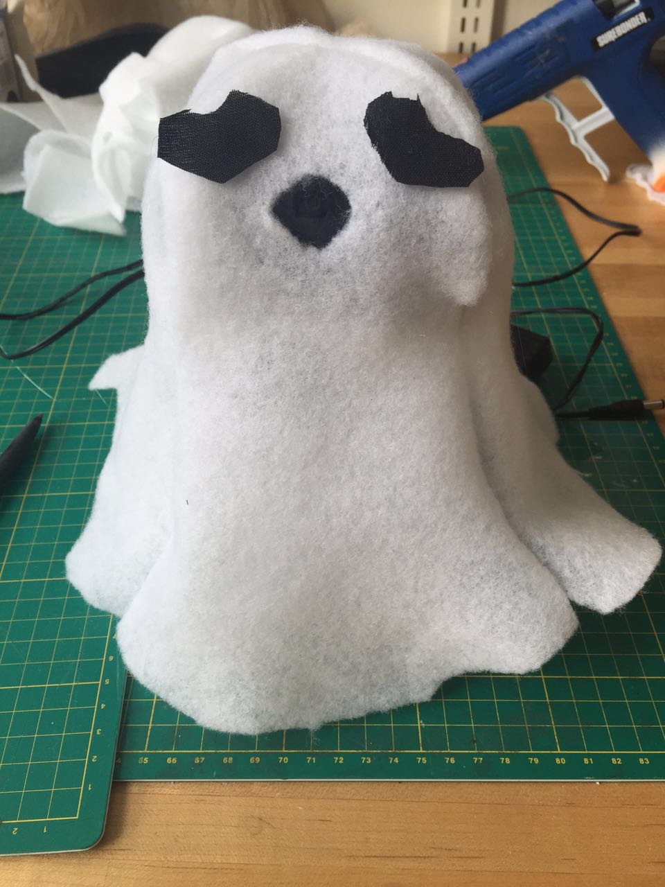 Say hi to my little ghost! (It did not become creppier... Now it seems even a bit cute...)
In a word I am quite happy with the result of my final project. I have put a lot effort in it and really learned a lot. My little
crappy-like ghostwas quite popular in the open house. It broght a lot of smile and happiness to the people walked by.
Say hi to my little ghost! (It did not become creppier... Now it seems even a bit cute...)
In a word I am quite happy with the result of my final project. I have put a lot effort in it and really learned a lot. My little
crappy-like ghostwas quite popular in the open house. It broght a lot of smile and happiness to the people walked by. Well only this little audience seemed dislike it...
Anyways, since I have made the project to this step so far, I will keep working on it in the future to make it to a real robotic slapping face arm I have planned initially. I will keep update this site once there is any new updates!
Materials
Cooper boards (tons of)ATmega 328
FTDI header
6 pin header
0.1uf capacitor
1uf capacitor
1k ohm resistors
LED
20MHz resonator
button
5v voltage regulator
MG996R servo motor
9V Battery——not recommended if you are working on servo motor, use 4*AA battery pack or 5V AC to DC adapter instead
FTDI Cable 5V/3.3V
3D printing filaments (for 3DWOX)
1/8" clear acrylic
Logitech C920 webcam -- this is the most expensive material I have purchased for this project ($61.99), for this project it could be replaced with a much cheaper one. I am purchasing this is because a high resolution (1920*1080) webcam will be needed for my research project later next semester.
Non woven poly fabric
Jumper wires (MM,MF,FF)
final codes
Python code for OpenCV and pySerialServo Control