Week 5 Electronics Design
This week we need to learn to design and make an echo hello-world board, add a button and LED (with current-limiting resistor, check the design rules and make it. So basically we have 3 main steps to do: design the board, mill the board, and do the solder work.
Board Design
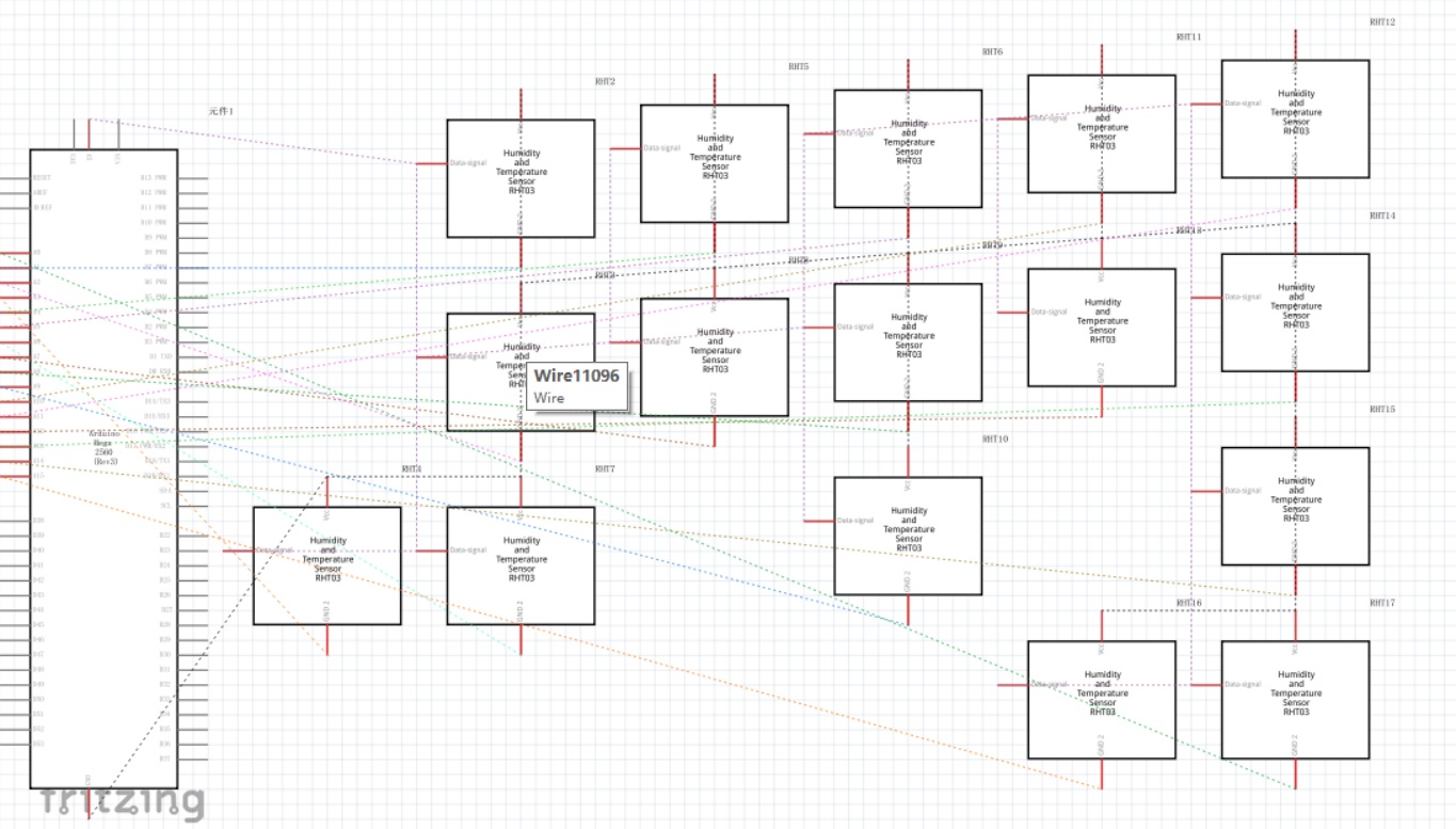
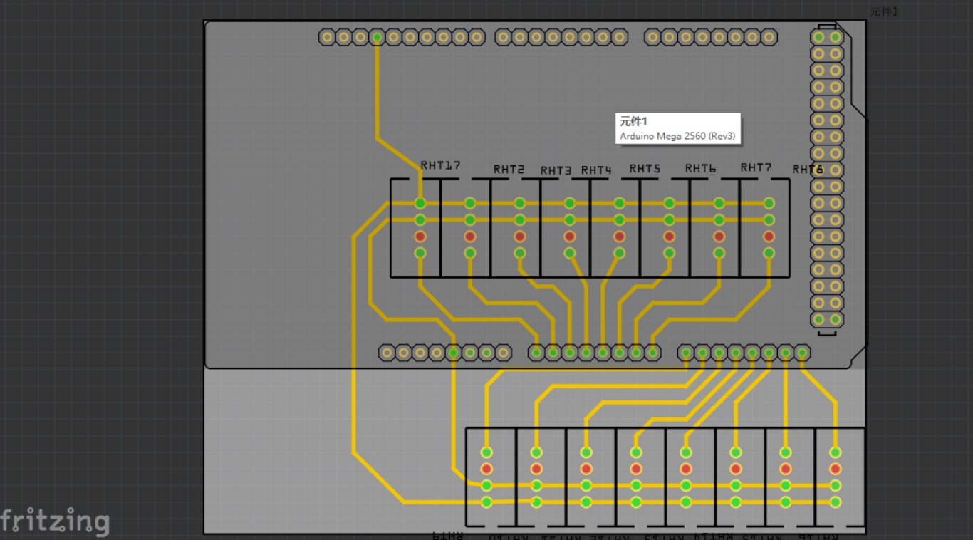
Before taking this course I only had limited experience in drawing schematics for Arduino boards on Fritzing, which in my point of view is a quite friendly way for newbies to start from and get a sense of schematic and board design. It is hobby-oriented software so there are a lot of limitations, but I am still mentioning this because it kind of helped me to transfer from the stage of knowing nothing about electronics to doing something with more professional software such as Eagle. Also, at the very beginning stage, adding components (button and LED) in eagle is a task that frightened me, so I used the breadboard interface of fritzing to simplify the situation and figure out what I need to do, then turn back to Eagle.
But the more important part of the week (and in the later of the semester) is to learn how to use Eagle.
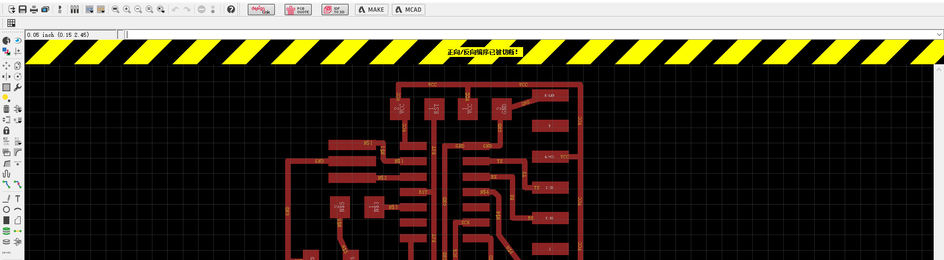 · *caution: don't close one of the two views, the link will break.
Every time working a project, there will be two windows: one for schematic and one for board, these two interfaces are linked to each other. Thus when I add a new component in the schematic, it will also be added in the board. If one window is closed, there will be a yellow and black warning telling you that the linkage has been cut. Under this situation any updates on one side won't be updated to another. So you need to either switch on the missing window or close the remaining window and open the whole project again.
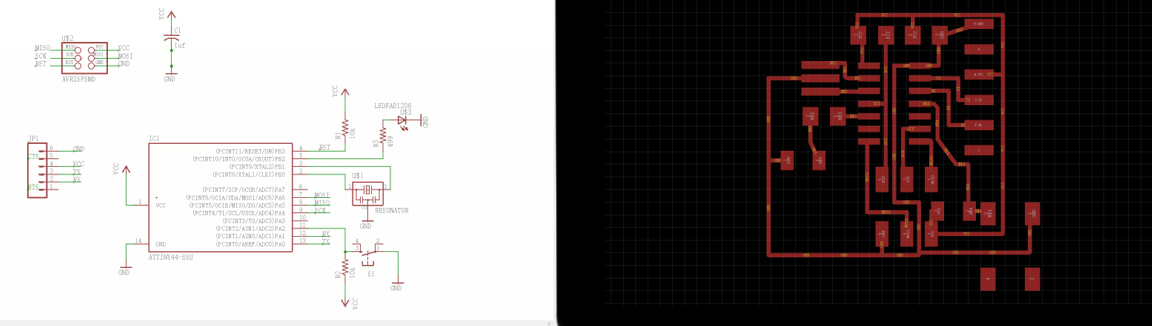 I don't know how this happen but my Eagle was downloaded as Chinese version,
maybe it changes the language based on the system default language.
I don't know how this happen but my Eagle was downloaded as Chinese version,
maybe it changes the language based on the system default language.Following the tutorial here, I redrawed my echo hello world board and added a button and LED.
*Caution2: Never use the auto-routing in eagle, in most of the cases it will become a disaster!
While routing the board, I have met the problem of "not allowing me to place components outside area which is permitted", which seems to be a problem in the free version of Eagle. But since I am not making a large board, to solve this problem is to find out the area that is allowed, usually it is the top left side from your original boarder of the board.
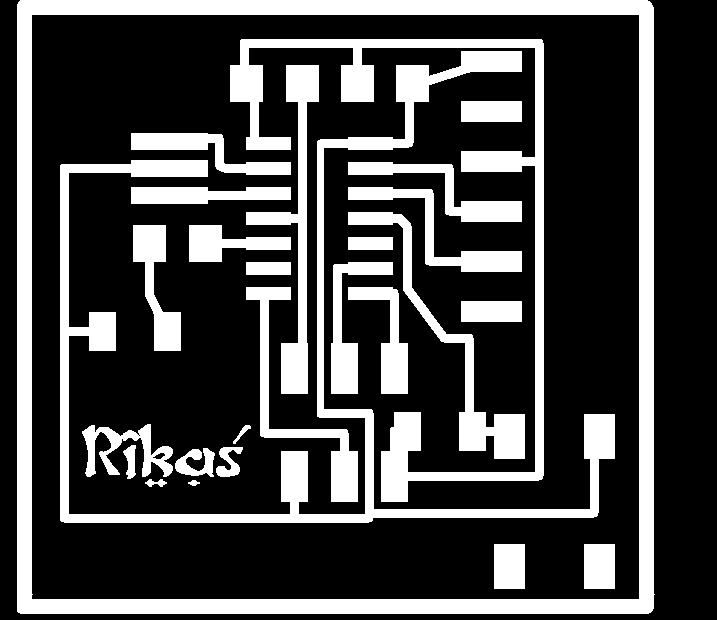
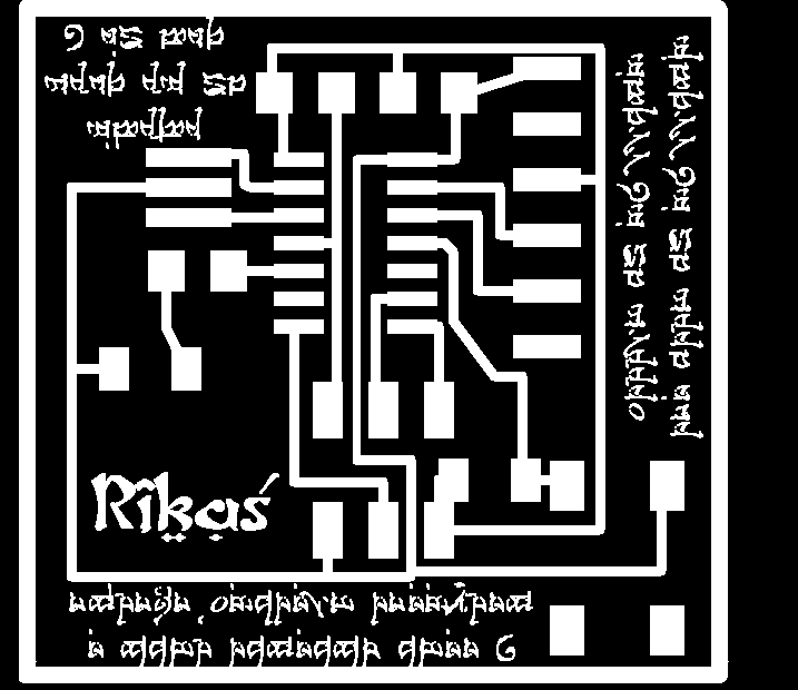
After exporting the png file (remember to deselect all other layers except for the top and save in single color (In Board window: View ' Layer ' deselect all then click on "1 top", then click OK ), I drew outer traces for the board in Photoshop and then added some spell like words for fun. But later I realized that the endmill is not thin enough to make it and it will cost more time to mill the board, so I erased them, just keeping my name on it.
Board Making
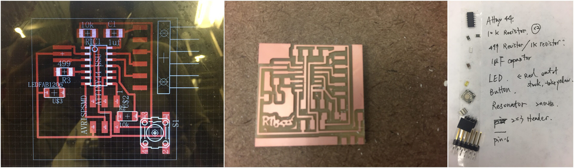
 After finishing designing the board it's time to go to the shop to make it.
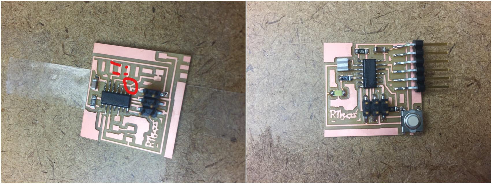
I noticed a there is a short on the traces while doing the soldering. I used
a cutter to cut it apart and checked with a multimeter to make sure it's safe.
After finishing designing the board it's time to go to the shop to make it.
I noticed a there is a short on the traces while doing the soldering. I used
a cutter to cut it apart and checked with a multimeter to make sure it's safe.And here is my board! Looking forward to the week to learn how to program it!
Simulation
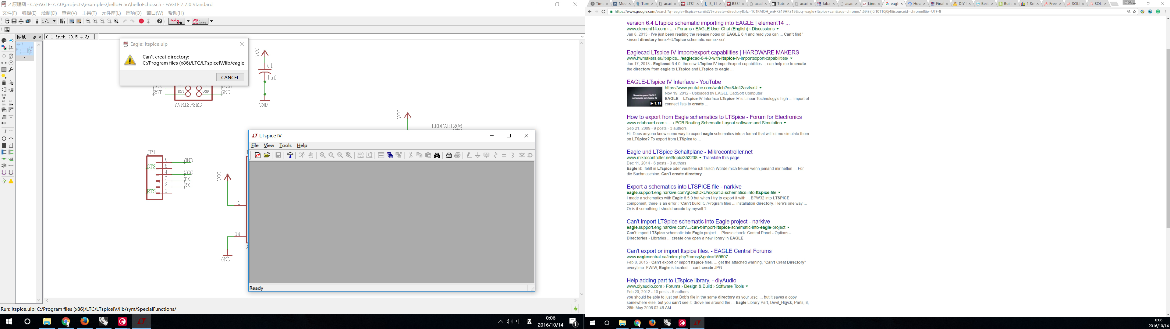
I tried to search for a software simulation. I watched this tutorial and downloaded LT Spice IV later in the week. But it did not work as described in the video and I don't know why. Maybe I will turn back to this later or just use the simulator in the shop if needed.