Pranam Tries To Make Things
MAS.863 - 2016
Week 12: Networking and Communications
Interfacing the Phototransistor with a Bluetooth Module
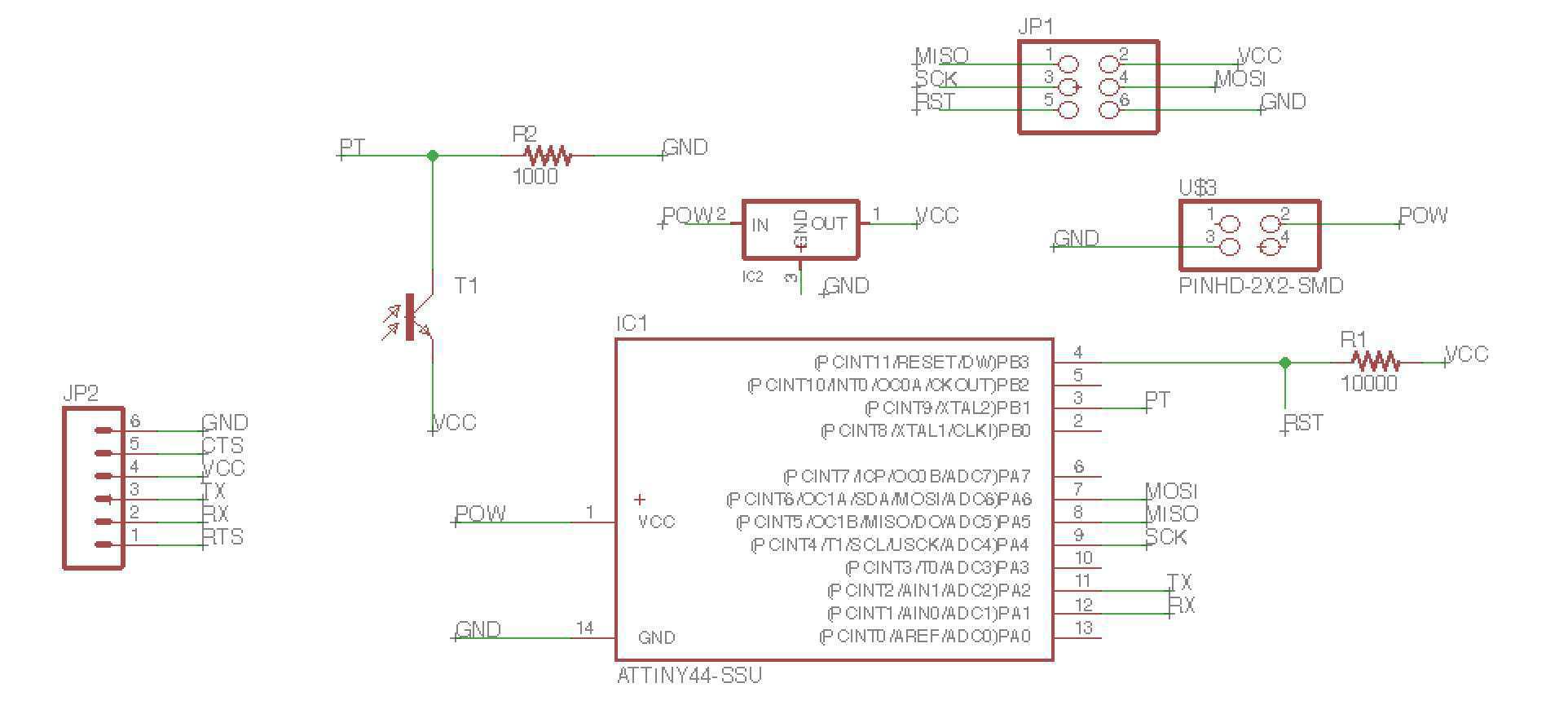
So instead of a simple graphical representation on the computer, a cooler, more interesting idea that deals with our networking and communications week will be to add a Bluetooth Low Energy module to the board that can read voltage data to a molecular biologist's cell phone, telling them when bacteria in a culture tube is ready to harvest and extract. In actuality, not much needs to be changed to the board, other than to have the FTDI header's TX and RX pins be connected to the microcontroller. But to do that, I have to use an ATTiny with more pins -- on to the ATTiny44! Just as a note, I decided to separate the LED board from the phototransistor board, so to spatially arrange the device in a clean manner. The 9V battery will still connect to both boards, but with parallel wires.

Figure 1. Updated phototransistor schematic with TX and RX pins connected to ATTiny44.
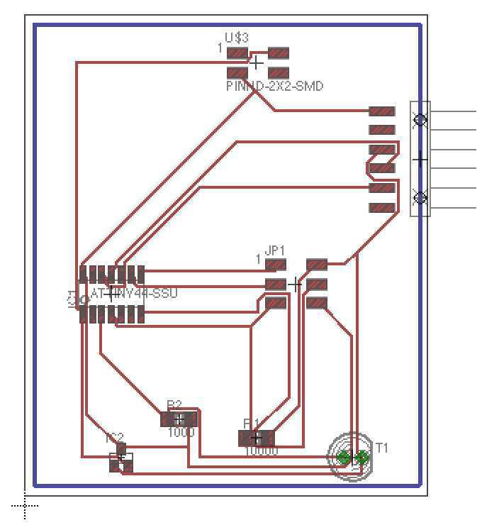
After designing, I went back to the autorouter, and got a nice (but weird looking) arrangement that I will to mill and stuff.

Figure 2. Autorouted phototransistor board.
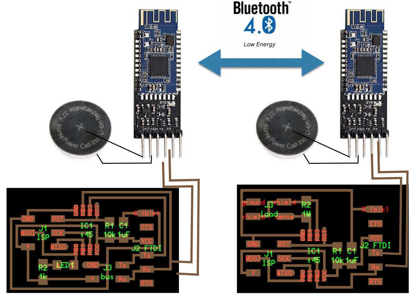
The plan is to use an HM-10 BlueTooth LE module that can connect to the 5 pin header, as mentioned by Thras in a recent email to the CBA section. The idea will be to do a Bluetooth connection between the low energy module and the bluetooth device in my iPhone, which can be read by a simple Bluetooth communications app already available on the App Store like LightBlue Explorer. These modules that I can attach to the board will be available soon.

Figure 3. Hello World Bluetooth demo.
Networking and Communications actually ended up becoming the cornerstone of my Final Project, where I integrated the HM-10 Bluetooth LE to read out OD measurements for the FabSpec.
| Activity | Tools Used |
|---|---|
| Designing The Board | Eagle |
| Milling The Board | Modela |
| Stuffing the Board | Soldering Stuff, Electronics |
| Reading the Board | Arduino, iPhone |