Pranam Tries To Make Things
MAS.863 - 2016
Week 2: Electronics Production
Stuffing the FabISP Circuit Board
Oh no! Electronics! I am actually very scared of electronics work, because I am so bad at it. Sure, I understand the physics behind electricity and magnetism, but ask me to put together a breadboard or calculate capacitance and resistance, and I will stare at you blankly. Safe to say, I was nervous for this week's assignment.
This week, we learned how to mill a printed circuit board (PCB) and surface solder components to it. We all made the same circuit a Fab ISP (in-system programmer) to be used with micro-controllers later in the semester. For this week, the class was given the traces and used the online fab modules to mill the circuit out. Here is the outline of the traces:
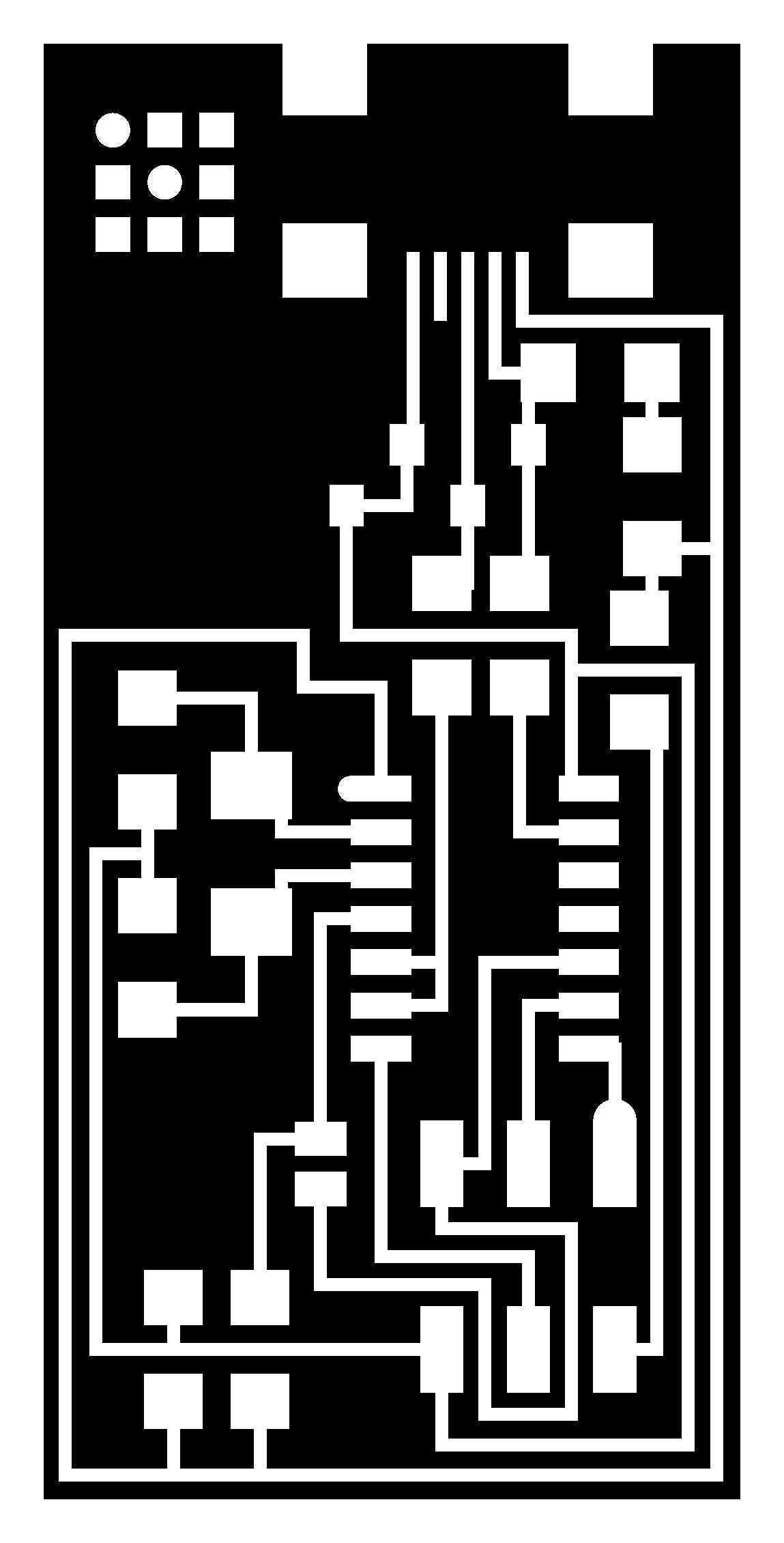
Figure 1. The template trace that is loaded onto the Modela mill to create the board. A rectangular outline file allows us to cut out the trace in the end.
First off: milling the circuit board! This proved to be the most difficult taks for me. It took almost 30+ iterations for me to get this correct. For those who know me well, I usually get things done really quickly, but this week I couldn't get anything done until the last day because I couldn't mill -- it was that bad! And all you really have to do is postion the board properly and let the Fab Module talk to the machine. I couldn't even do that correctly! FML...Anyway, on the last day, I figured out how to flatten the board properly, tape it on, and zero the mill to get it to cut both the trace and outline nicely. I have to say, the Fab Modules are really wonderful tools!
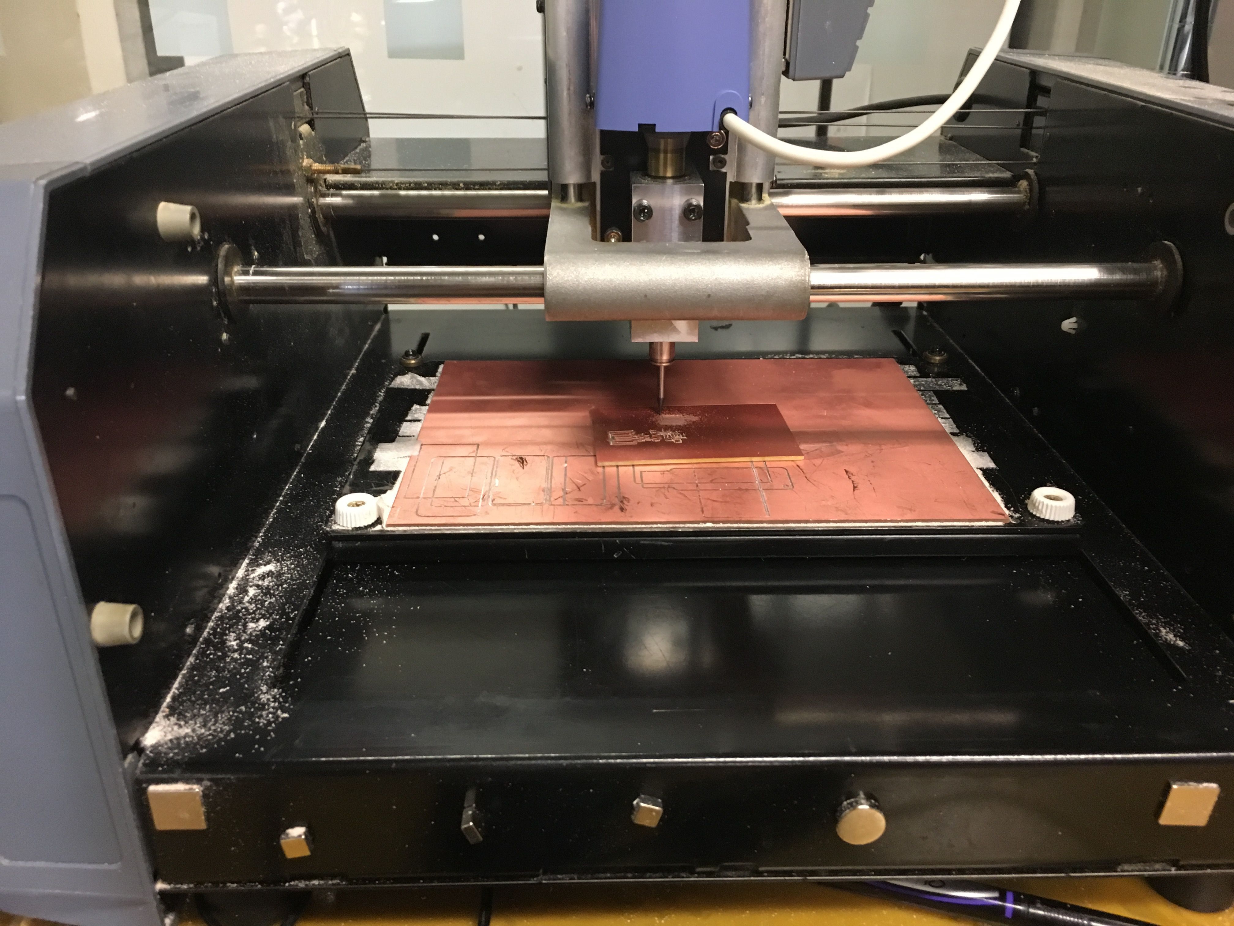
Figure 2. Milling my board on the Modela -- it worked finally!
Next, it was time to fill the board! Filling the board really just means soldering all of the parts on. To know what parts are needed to make the FabISP work, I just took a look at the circuit schematic provided. To stuff the board, I used a little solder on one space for each component, mounted the components on top of that, adjusted and flattened them, and then attached the other side with more solder. I used tweezers to hold the component in place and juggled the soldering iron and the solder to connect it. A third hand would surely have been helpful! For bigger components like the ATtiny, I had to be extra careful to make sure the pins were in the right place and the component was attached, so to not create bridges between pins.
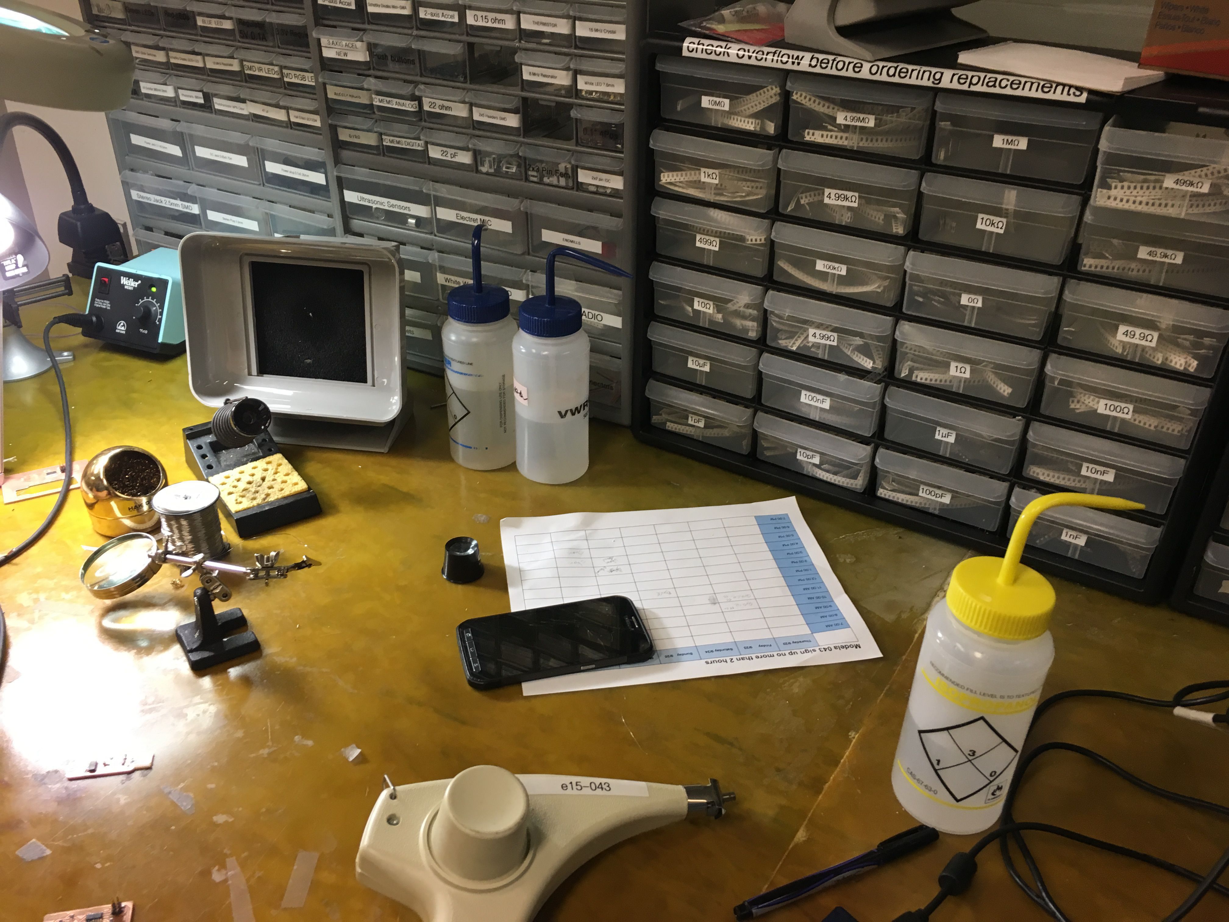
Figure 3. My workstation with all of the components I needed to populate the board!
After a lot of patience and work, I filled the board and soldered everything together! It really felt amazing once everything was put into place -- quite beautiful actually!
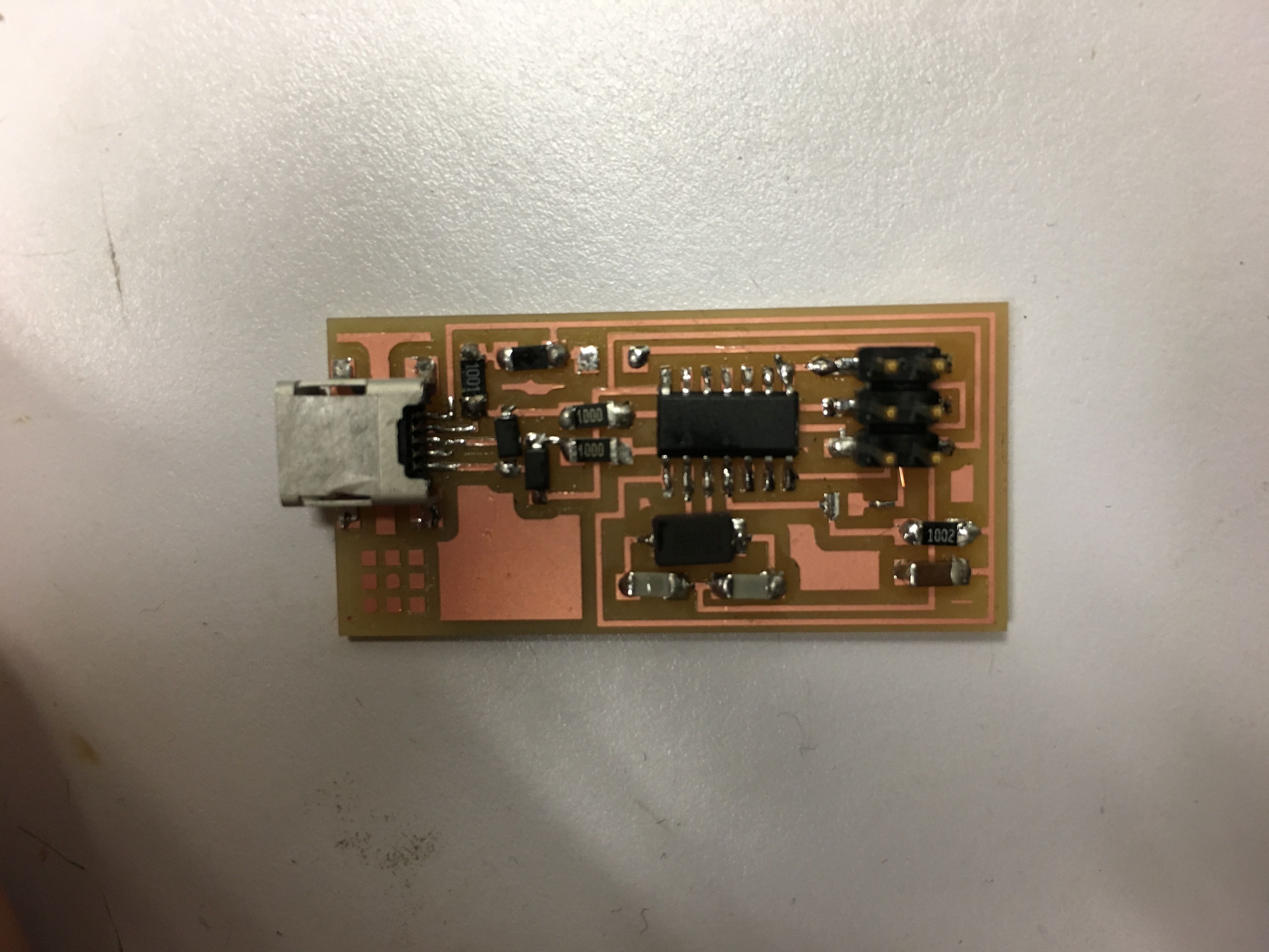
Figure 4. The final soldered board.
Now, it was time to test the board! The first test is to see if the programmer connects to the board and delivers power to it -- basically a first indicaton of whether the board works or not. I was super happy and lucky that the light flashed green on the first try!
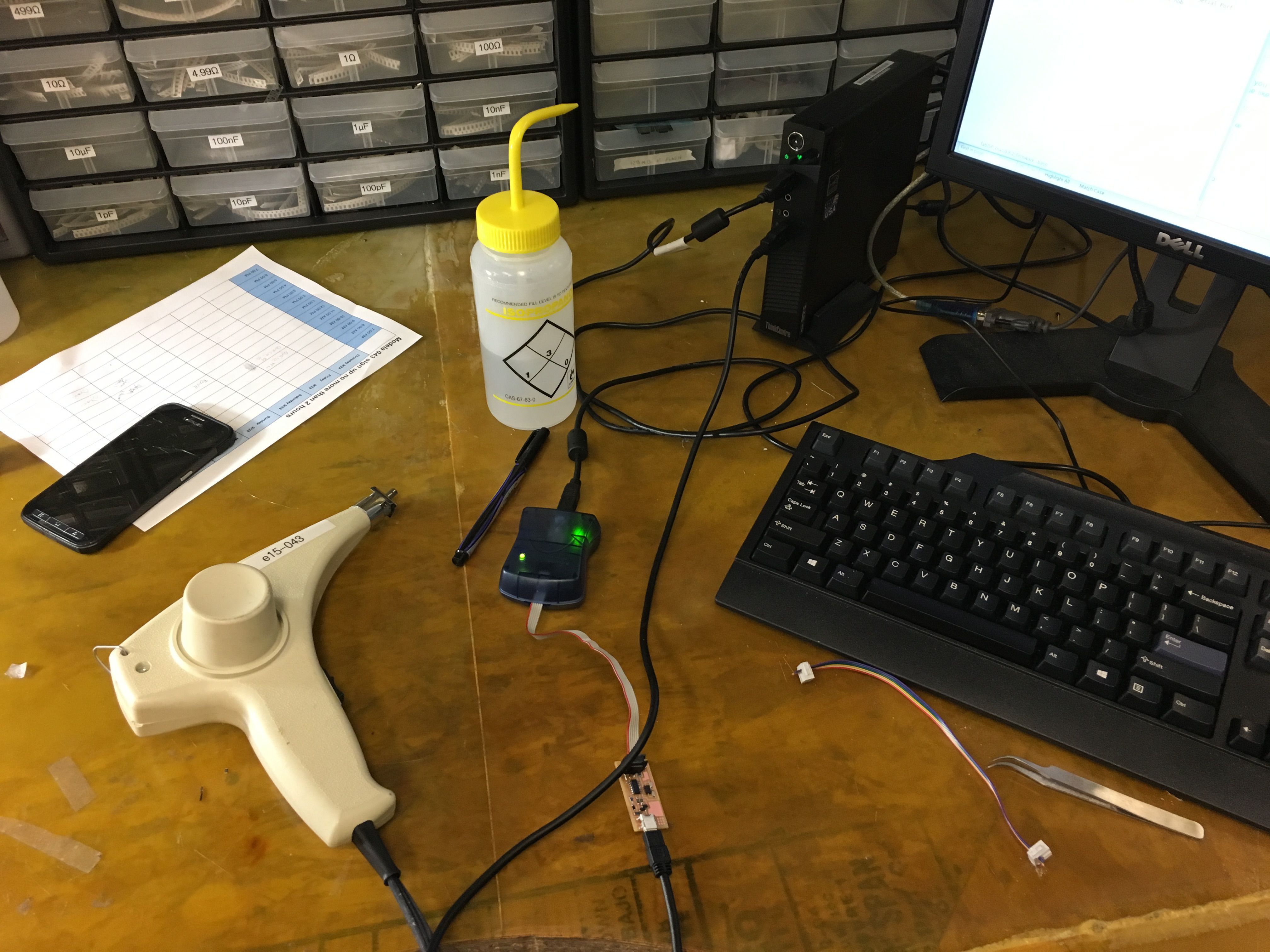
Figure 4. THE BOARD TURNS ON!
Finally, we program it and then test to see if the computer recognizes it as a USB that can program other boards. At first, my board wasn't able to be programmed, but after further inspection from Will and Eric, the two awesome TA's in the CBA, I realized that my USB and ATtiny pins were not fully soldered on. After doing that and programming the board correctly, I connected the board to the computer as a USB without being connected the programmer anymore, and it finally recognized my board! What a great way to end the fab week!
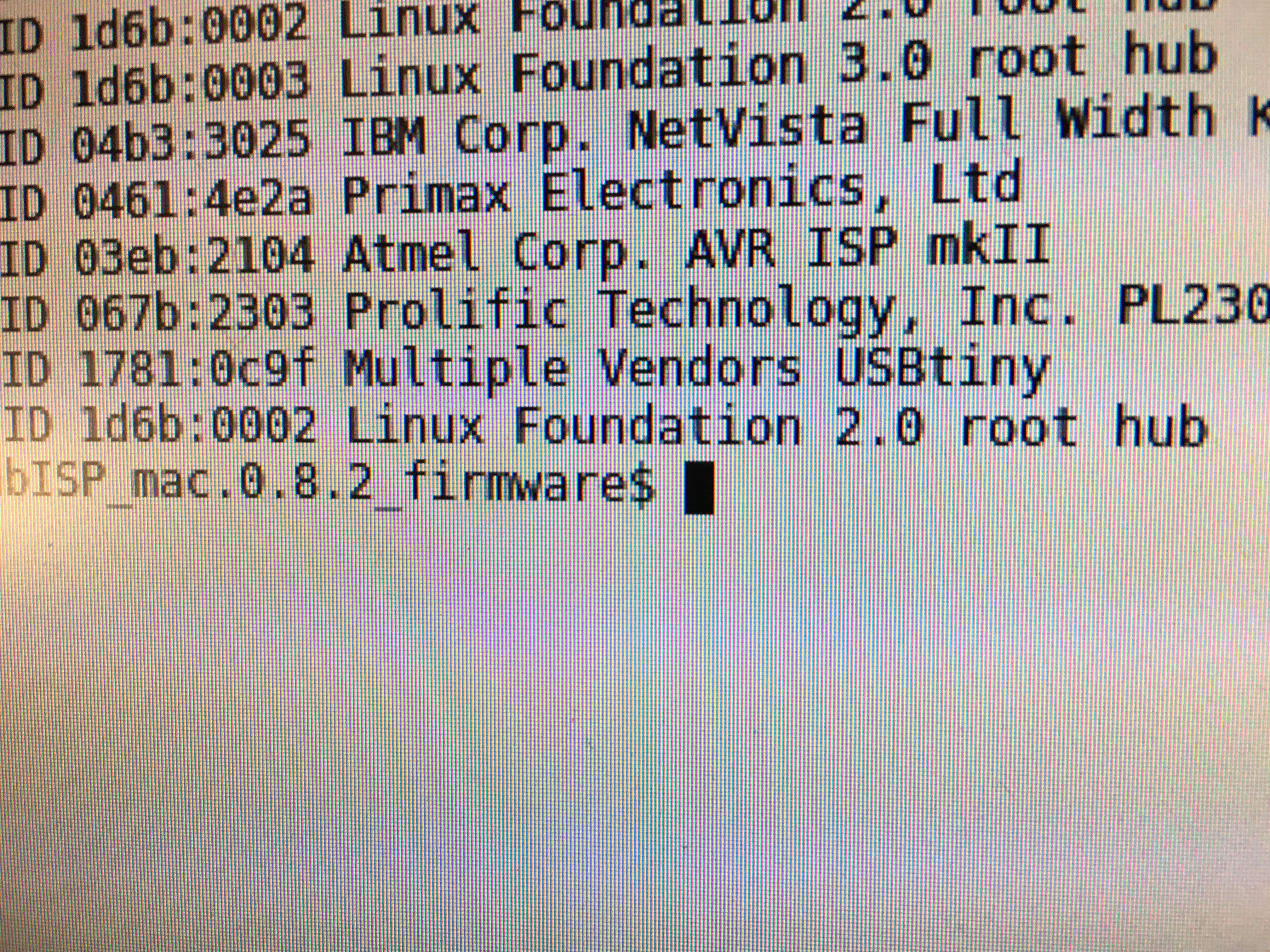
Figure 5. The computer recognizes my board as a valid USB input!
| Activity | Tools Used |
|---|---|
| PCB Milling | Modela |
| Board Filling | Soldering Iron and Flux |