Pranam Tries To Make Things
MAS.863 - 2016
Week 8: Input Devices
Reading a Photoresistor
Back to electronics! This week, our assignment was to make a circuit that would receive an input signal from a new component on the board.
Since my final project will be a continuous cell culture device that reads cell density, I decided to construct a board that would receive a light signal to a photoresistor, whose could be read as a voltage to be processed.
There was already a nice photoresistor circuit on the page for this week, so I decided to make it and read it. First, as always, I milled the traces and outline.
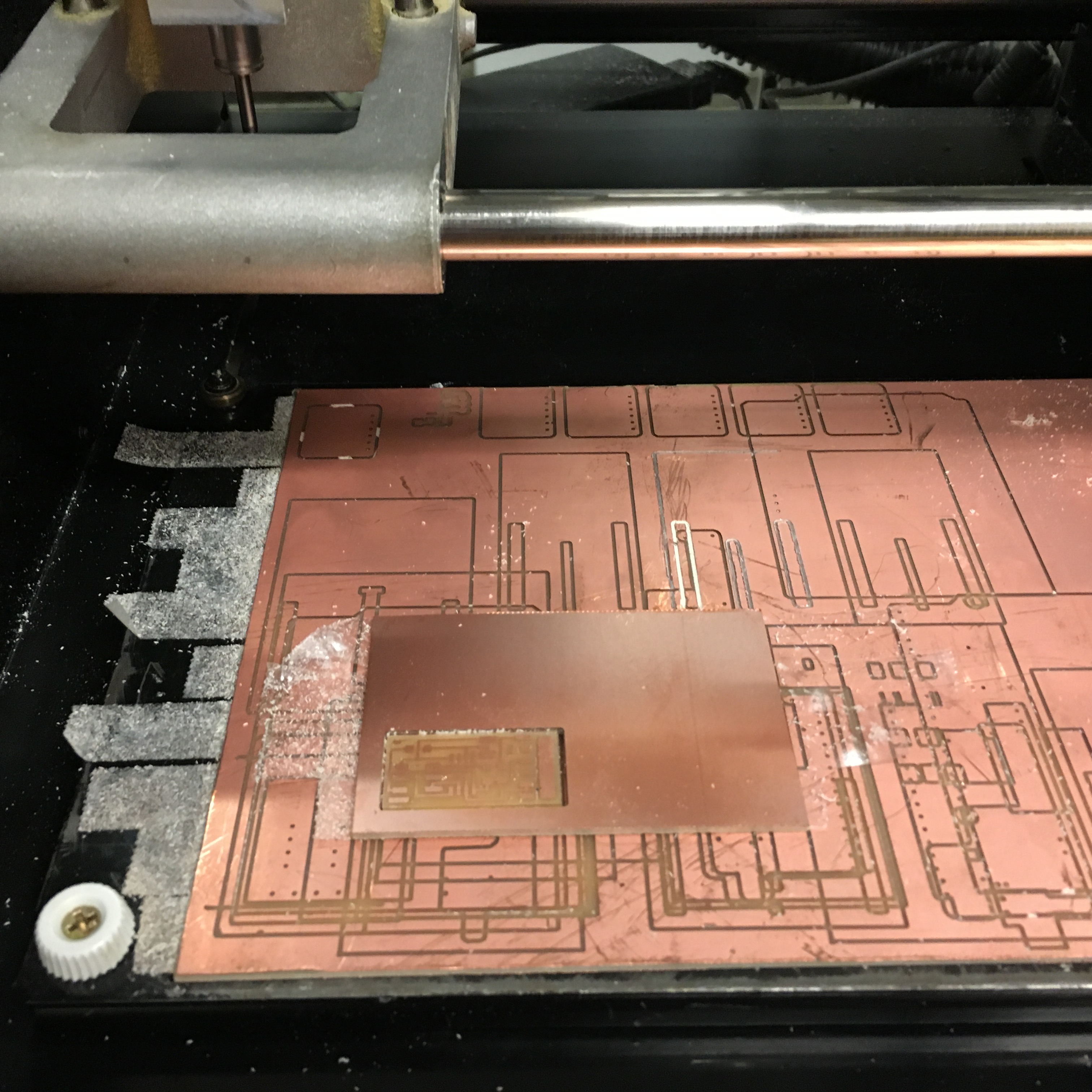
Figure 1. Milling the phototransistor board.
The board is simple enough, and utilizes the ATTiny45 microcontroller. The phototransistor is connected to Pin 2 and Pin 4, which is Ground. After stuffing the board, I checked to see if power was going through it.
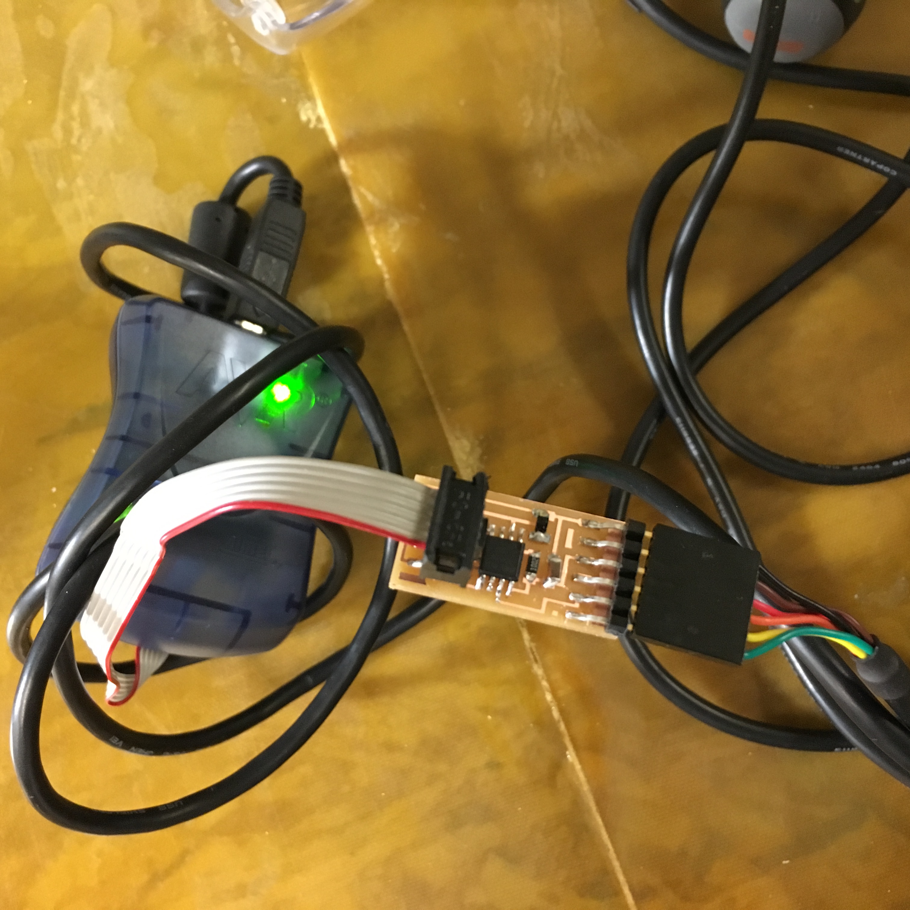
Figure 2. Power successfully going through the board.
Finally, the goal was to read in the analog signal. As a reference, I used the analog signal example Arduino code to familiarize myself on how to read the signal and do something with the data. Unfortunately, I tried to use the built-in Serial class, and it just would not recognize my declarations.
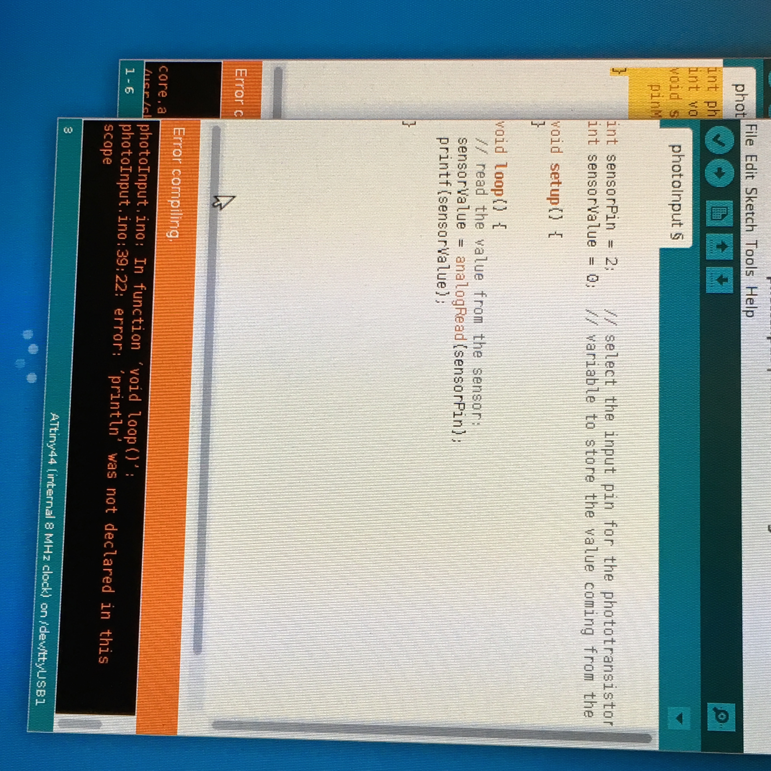
Figure 3. Arduino software not recognizing Serial class declarations.
With the help of TA Eric, I was able to use the SoftwareSerial class, and have the code compile. Next steps are to include an LED in an Eagle-designed circuit to have a better readout. I'll try to have that done by the week's end!
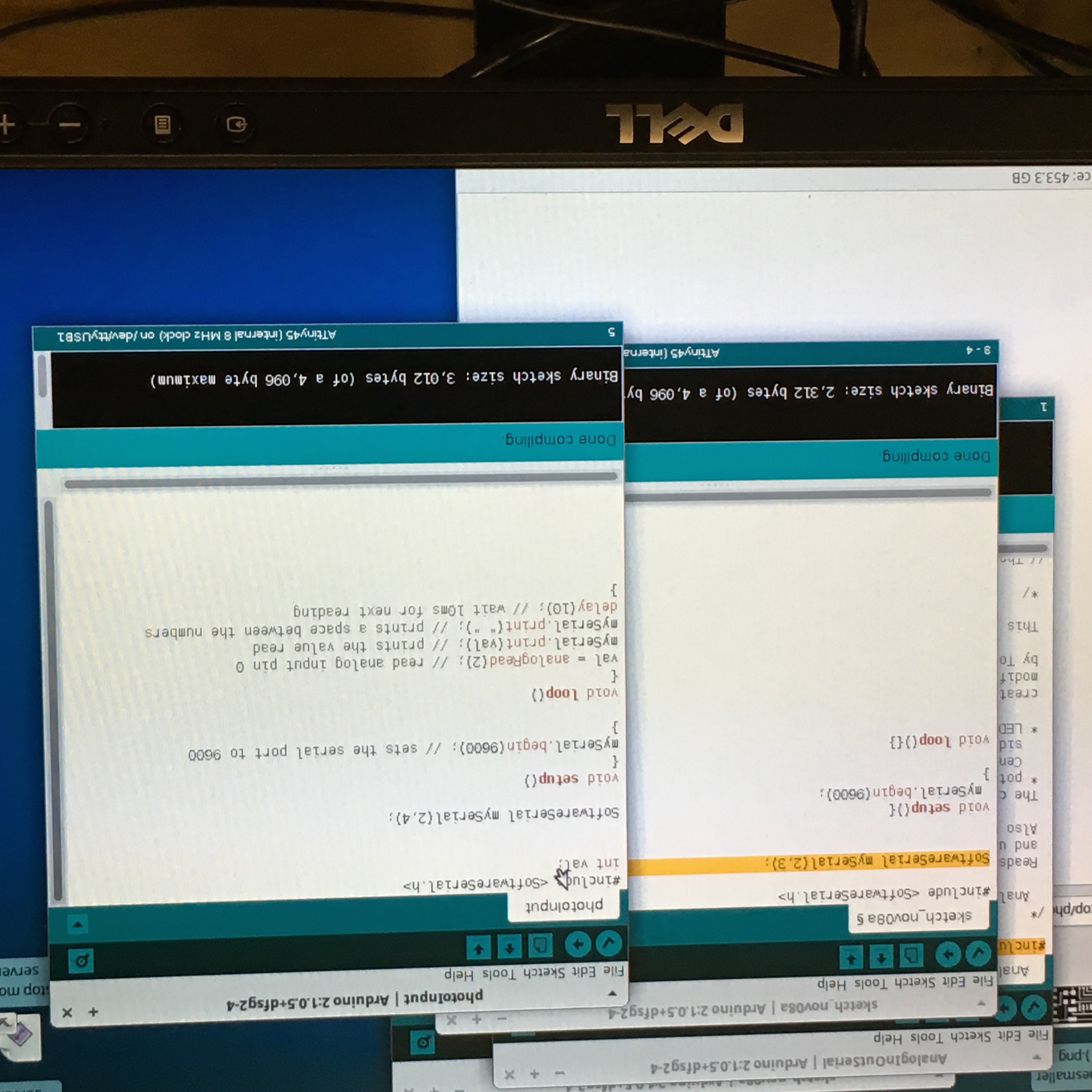
Figure 4. Arduino code compiling!
| Activity | Tools Used |
|---|---|
| Milling The Board | Modela |
| Programming the Board | ATTiny45, Phototransistor Opaque, Arduino IDE, AVR mkII |