-

- Computer-Aided Design 01
- Parametric Construction 02
- Electronics Production 03
- 3D Printing 04
- Electronics Design 05
- Computer-Controlled Machining 06
- Embedding Programming 07
- Molding + Casting 08
- Output Devices 09
- Machine Design 10
- Input Devices 11
- Interface + App Programming 12
- Networking + Communications 13
- Composites 14
- Final Project 15
HOW TO MAKE (ALMOST) ANYTHING
Lily Gabaree
Electronics Design
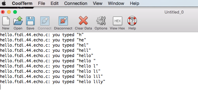
This week, we're designing, milling, stuffing, and programming a board that echoes back serial input.
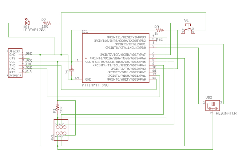
Designing the Schematic and Board
I started out by reading several Sparkfun tutorials about Eagle and board schematics. It seemed to be general best practice to lay out components as separate units, labeling the ends, but I had a hard time visualizing the whole thing that way, and ended up making the schematic as a messy-but-connected whole.
My roommate Matt gave me some advice about how to select an appropriate pull-resistor for the button, and I added one LED and a corresponding resistor.
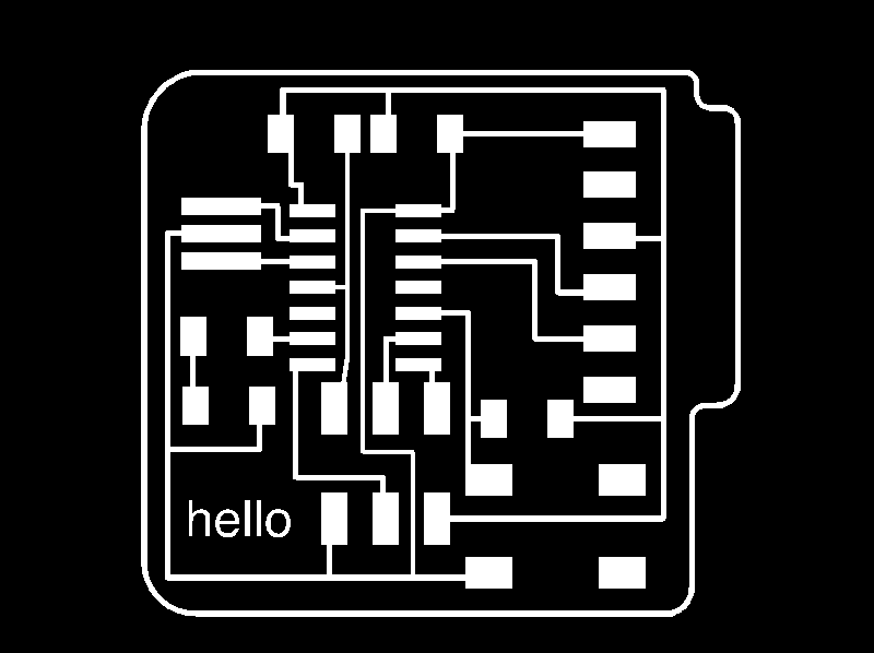
Laying out the traces was tricky - I had a bit of a jam in the center of my ATTiny44. For the board dimension outline, I decided to curve the edges a bit, and add a support for the FTDI header.
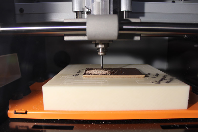
PBC Construction
Once I made my traces, I exported them as monochrome (black and white) and sent them over to mods.
The first problem I ran into was that some of the traces were a little too close together, so when mods calculated the toolpath, it merged some of the elements. I tried refining the grid in Eagle and moving the lines a bit but it was still tight and some paths remained merged. Rob suggested modifying the properties of the problematic lines to be .008” instead of .01, and that fixed the problem.
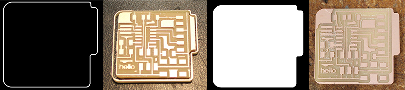
The first board I cut out had a messed up outline - I’d exported the outline from Eagle and made no modifications, and didn’t notice that it was going to mill the outline of the outline, rather than just an outline itself. Which meant that it ended up shaving things too close on the interior, and removing my top trace.
So I redid the outline in Photoshop, making the entire interior of the outline white, and the outside black, so it would calculate as a single toolpath.
I ran the job and had yet another problem - when I went to cut out the outline, the bit moved way left in the machine - totally beyond my board - so I quickly paused it. Turns out that the outline file had imported at a 72 dpi instead of 1000, so it was interpreted as a giant (22 inch) file. I changed the dpi and ran it again; this time, success.
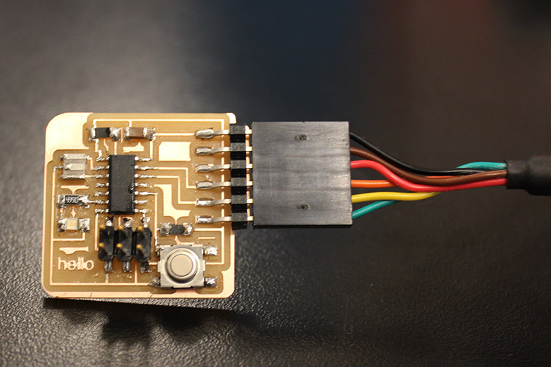
Board Assembly
I am not finding soldering to be a meditative experience. The traces and components are so tiny, it’s hard not to get shaky hands when lining them up. Many thanks to Dixon for his intervention and wicking tape.
Programming the Board
After I’d gotten all the parts stuffed, Rob helped me program the board; running the make file was fine, the fuses were verified, but when I tried to write the hex code it failed, I think because the clock (resonator) wasn’t well secured. Once that was resoldered, I was able to fully program the board.
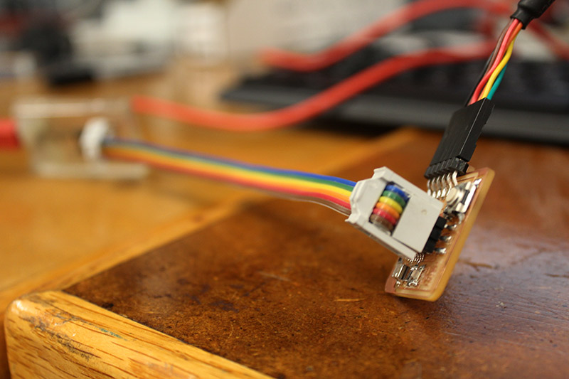
I installed FTDI drivers and CoolTerm, and got the program running.