-

- Computer-Aided Design 01
- Parametric Construction 02
- Electronics Production 03
- 3D Printing 04
- Electronics Design 05
- Computer-Controlled Machining 06
- Embedding Programming 07
- Molding + Casting 08
- Output Devices 09
- Machine Design 10
- Input Devices 11
- Interface + App Programming 12
- Networking + Communications 13
- Composites 14
- Final Project 15
HOW TO MAKE (ALMOST) ANYTHING
Lily Gabaree
Input Devices
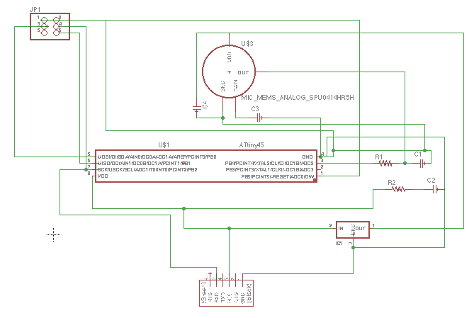
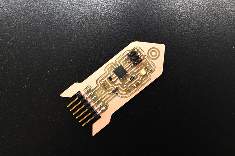
I've been swamped this week, so I'm keeping it simple and trying just one component that will likely end up in my final project: detecting sound. I ended up making a board using the analog MEMS microphone, of which the Harvard shop has an ample supply.
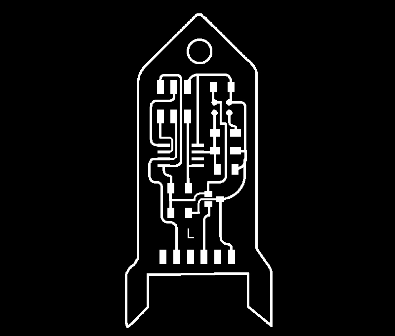
While thinking about the board layout, I realized that the FTDI pinout, which always sticks out a lot, could be a design feature of sorts if I made the board into a rocketship.
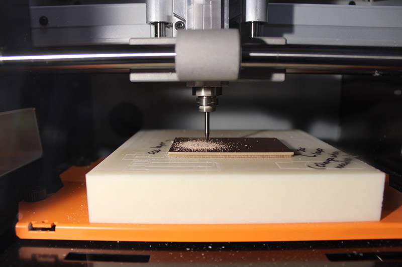
Milling took longer than it should have. I got thrown off by the dimensions listed for the board in MODS, one of which was over three inches. I wondered if this was because of a bug with Eagle in Mac (I'd seen others write about doubling the DPI to correct incorrect exports). So I doubled the DPI and started milling, and quickly discovered that the board was too small. I ended up exporting from Eagle again with a different DPI (500, instead of 150) and as a "window" instead of "full" image, and this time the file exported in the correct size and opened properly in MODS.
Soldering was harder than usual, because the microphone requires reflow soldering - it has four tiny spots on the underside that need to be soldered to pads on the board, so you can't get at them with a soldering iron from the side. I applied a very very tiny amount of solder to each of the spots on the microphone - so little that I was dipping into each previous spot in order to fill the next, rather than bringing in more solder - and then applied a bit more to the pads on the board. Once all the spots were ready, I angled the microphone diagonally above the board, brought in the heat gun tip, and warmed up the microphone and the board concurrently. Once it was hot, I sandwiched them together and wiggled the board around until it felt like it lined up.
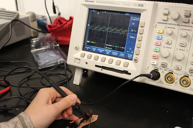
Rob and I tested the board with an oscilloscope and some shop singing. It works!
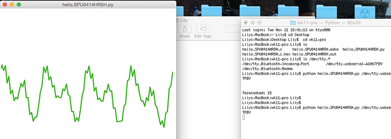
I'm still working on getting comfortable with programming boards. I used Neil's c code and makefile for the MEMS board, and programmed my own. Then I tried to get the python visualizer to work.
- pip install PySerial
- ls /dev/tty.*
- python hello.SPU0414HR5H.py /dev/tty.usbserial-A703EBE1
At first, when I ran the code, Python would pop up, but would get stuck loading and I'd have to force quit the whole thing. Richard suggested that it might have to do with me not having an up-to-date version of tkinter - he had had a similar problem - so I updated that, and Python, and ran it again, and it still didn't work. Then he offered for me to try it with his own FTDI cable, instead of the lab one I was using, and it worked! I'm not sure what was wrong with the cable, since it was capable of powering my board.
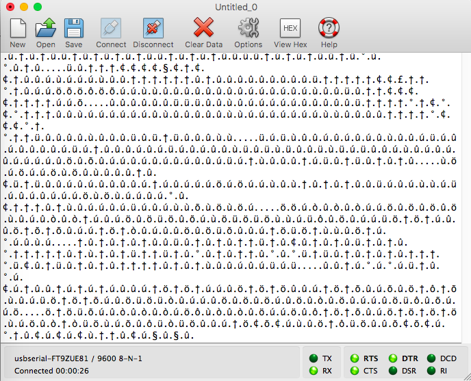
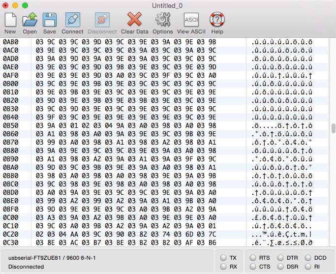
I also wanted to be able to get a numerical output from the board - so I could, in the future, have projects that compared the input from different microphones - but my understanding is that this will require some more Python knowledge (I'm new to it). I first tried viewing the output in CoolTerm; I was initially thrown by the fact that it was responding with a bunch of inscrutable symbols, but once I clicked on "View Hex" things started looking a little more familiar. It seems that these values can be translated into numerical form, but I can't do it in Coolterm...so that's something I'll be trying to figure out this weekend.