-

- Computer-Aided Design 01
- Parametric Construction 02
- Electronics Production 03
- 3D Printing 04
- Electronics Design 05
- Computer-Controlled Machining 06
- Embedding Programming 07
- Molding + Casting 08
- Output Devices 09
- Machine Design 10
- Input Devices 11
- Interface + App Programming 12
- Networking + Communications 13
- Composites 14
- Final Project 15
HOW TO MAKE (ALMOST) ANYTHING
Lily Gabaree
Electronics Production
This week we are learning how to fabricate PCBs from circuit traces, assemble and solder the board components, and program the board.
PCB Machining
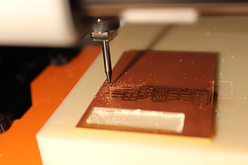
First, you place the circuitboard on the sacrificial layer of the mill (Roland SRM-20). The board needs to be well cleaned, and stuck firmly to the sacrificial layer with double-stick tape. I had some issues with an uneven sacrificial layer, so I scraped it down with a razor blade.
Once your board is secure, zero the tool and insert your endmill (1/64"). Once the endmill is secure, move the tool to the origin point (adjust if needed). Then, loosen the endmill and drop it down to the board.
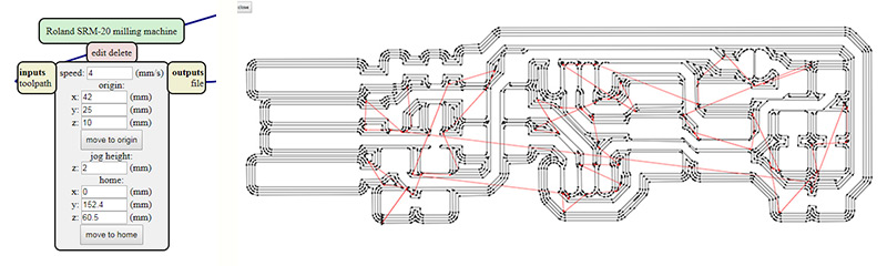
Neil's MODS program lets you load a PNG as traces, and calculates the appropriate specifications for the job on a given machine. I milled four offsets, as recommended.
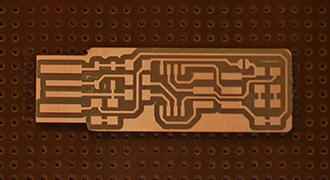
At this point, I went ahead and calculated the job and printed it; this ended up being a mistake. Here is a glamour shot of the board, mostly cut:
The problem here is the traces aren't really deep enough. Rob showed me that I need to firmly hold down the endmill to the board when I drop the z; otherwise it's a little high. So I repositioned the endmill, and cut over the traces again. Next, I ran the outline file, changing the bit to 1/32". Now the board is ready to be stuffed.
Board Assembly
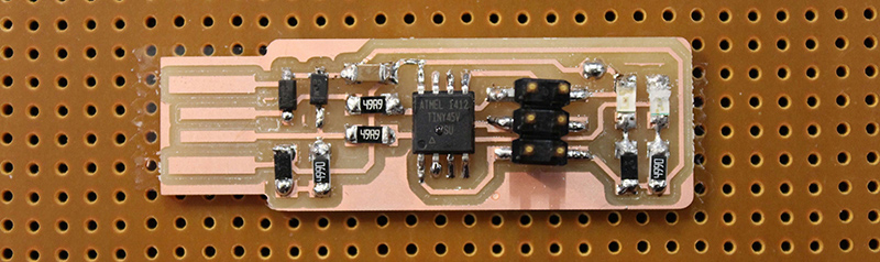
This was the hard part, because the components are TINY. I needed a microscope to determine the direction of some. I laid out all the components on double stick tape, making sure they were properly oriented so I wouldn't have to recheck while soldering. The components are:
- 2x 1kΩ resistors
- 2x 499Ω resistors
- 2x 49Ω resistors
- 2x 3.3v zener diodes
- 1x red LED
- 1x green LED
- 1x 100nF capacitor
- 1x 2x3 pin header
- 1x ATtiny45 or ATtiny85
I've mostly sautered circuits that didn't require tremendous precision, so it was a bit of challenge not to glob on too much solder. I did several practice rounds on a spare board before attempting my own.
I added all the components, and created a "bridge" out of solder near the ISP jumper.
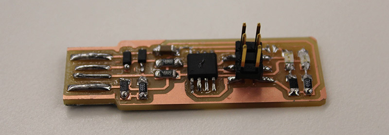
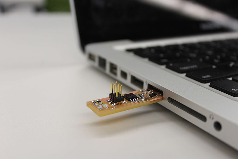
The last step was adding solder strips to the insert side of the board - otherwise, the connection wasn't tight enough. I ended up going over it twice, and adding a little tape to the back, to make it really secure. At this point, a comforting LED lit up when the board was inserted into a USB port.
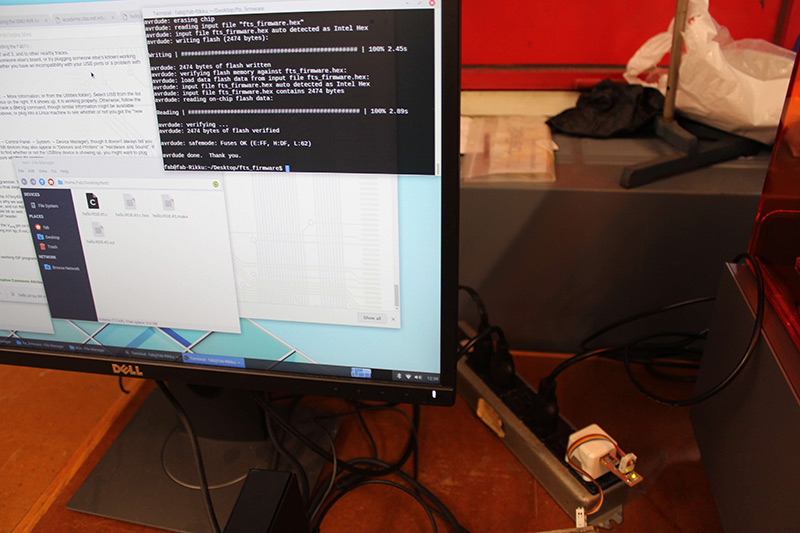
Programming the Board
I connected the board to another "programmer" board with a ISP cable, and programmed the ATtiny45. I confirmed the functionality by inserting it into the USB drive - it showed up as a device.
Once this step was done, I applied the solder braid and iron to the jumper bridge, disconnecting Vcc from the Vprog pin on the ISP header. Now the board functions as an ISP programmer.
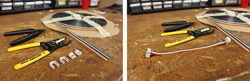
I also made my own IDC ISP cable.
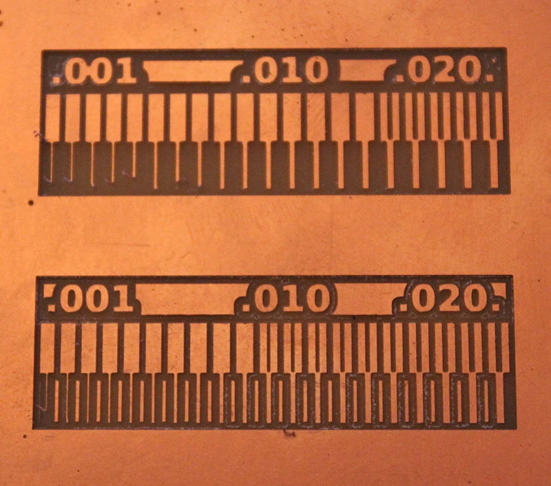
Characterizing the Machine
I went back on a different day to characterize the machine, since the .010" endmills came in (they were out at the Harvard shop last week). I halved the cut depth and the speed on Rob's advice, since the endmill is so delicate and prone to breaking. Here's a comparison cut of the 1/64" (top) vs. the .010" (bottom).