week 02
ELECTRONIC PRODUCTION
Tools + Methods
Roland Modela Mill
Soldering Iron
Existing Programmer
This week we made an AVR ISP Tiny Programmer from scratch. If you’re a novice to electronics like me then you’ll have no idea what that means. My advice this week is to blindly follow the instructions on Brian’s page (and, yes, you should actually read all of it) and then try and make sense of it at the end.
Fabricating the PCB
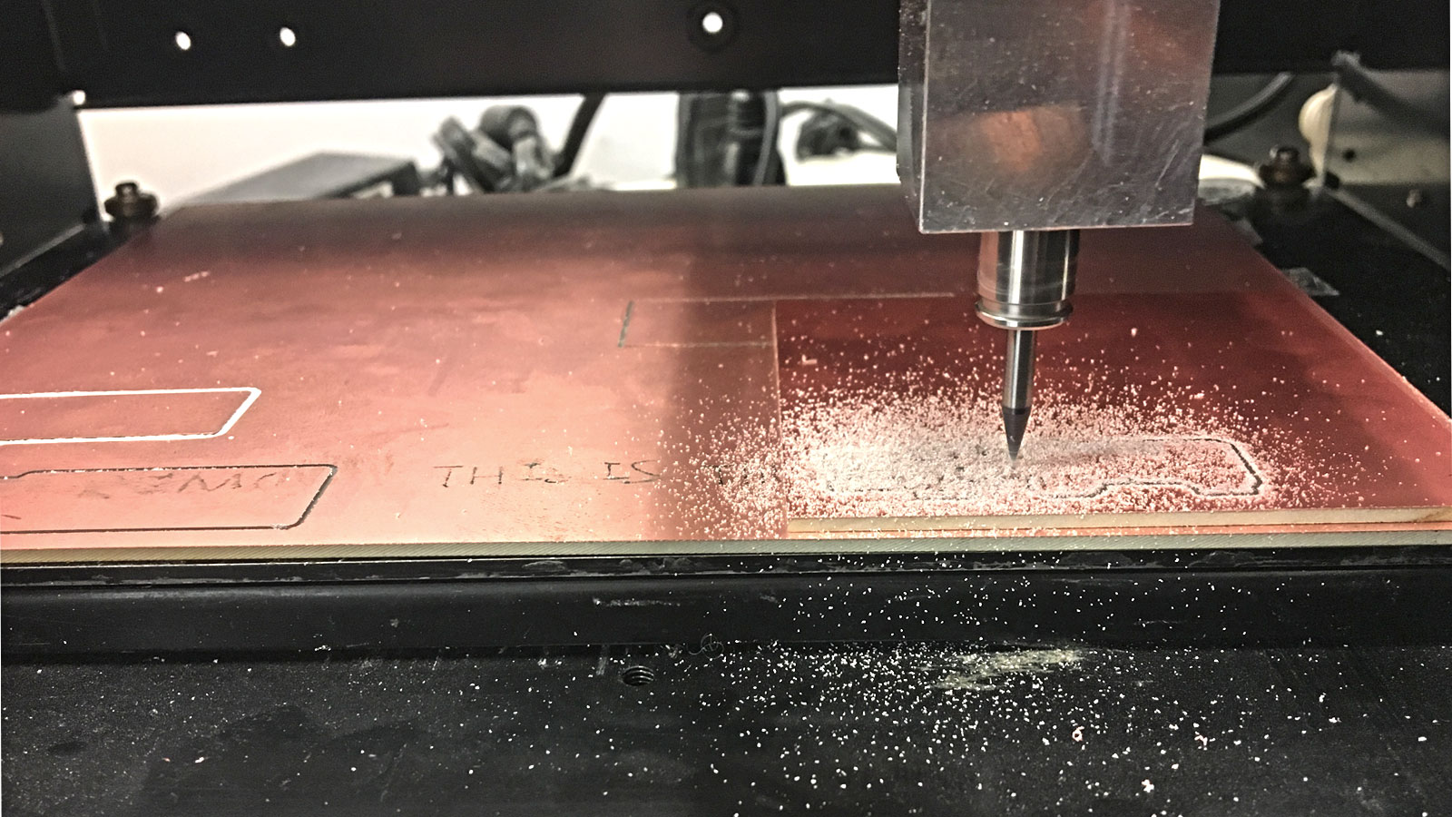
Milling the Board
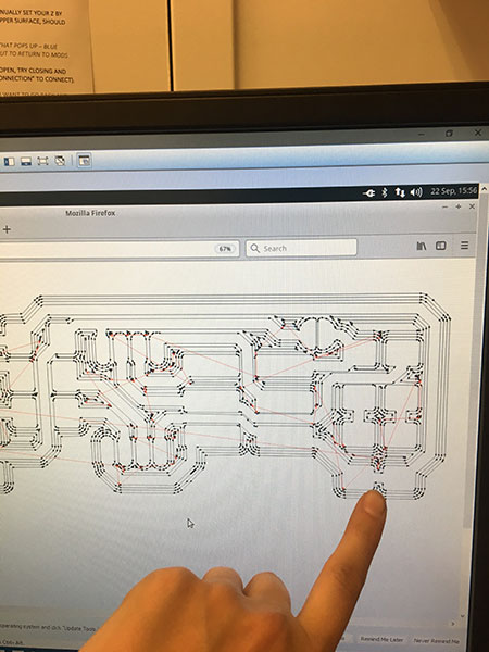
This week I used the Roland Modella Mill to fabricate a PCB, Printed Circuit Board. First I milled the circuit board for our programmer on a piece of copper coated plastic. Since we're using a subtractive process and copper is conductive, what we leave behind on the sheet will be the paths or 'wires' of the board.
I made the board in MIT’s Architecture Shop. The Shop Computer uses a Virtual Machine (VM) to communicate with the Modella so to begin: I opened up VMWare and ran Ubuntu. Then I made sure the Server was open (important later).
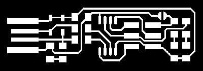
Using CBA Mods (right click CBA Logo>Programs>Server Program>Roland:mill:MDX-20), I uploaded a black and white PNG for the traces (make sure to use a high resolution). Then I selected “mill traces 1/64,” calculate, and made sure that status of the serial server said “socket open.” (If you are working in a lab within MIT you have to make sure the server is turned on before you do this).
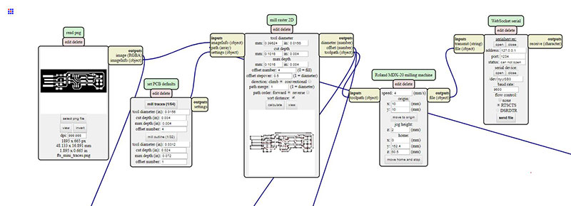 CBA Mods for the Roland MDX-20

Before I send the file I made sure to double check the machine. Make sure the piece of copper you’re using isn’t warped and make sure there aren’t too many cut outs on the sacrificial board underneath. (The first time I taped it down in a messy corner and it came up during the milling process. Not good). Once my board was firmly taped, I placed 1/64” bit in the collet. Then I jogged the head to where I wanted X/Y to start. I manually set the Z “zero” by loosening the set pins and guiding the bit to the top of the copper plate (I recommend pushing it down a little bit to ensure you cut through) and then retightening the set screws. Then, I sent the file through CBA Mods.
Fabricating the traces
To cut the piece out, I repeated the process: I uploaded a second PNG, this time selected “mill outline (1/32),” installed a 1/32” bit on the machine, set a new Z ‘zero’ manually, used THE SAME X/Y location to start, and send the file from mods.
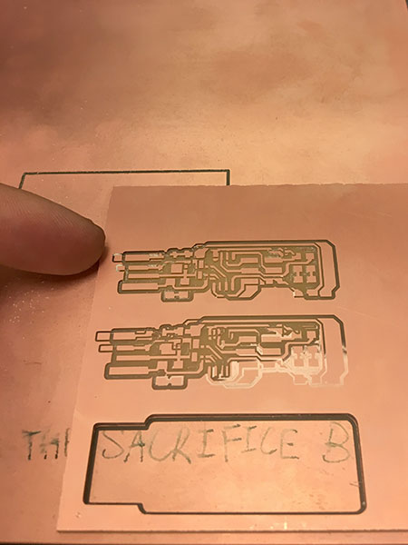
The first time I milled, my board separated from the bed because the sacrificial board didn’t have enough surface. The second time, I had the file almost complete without a problem but the last pass of milled seemed to get offset in the X axis. I double checked my calculated toolpaths in Mods and they did NOT look like this. So I tried to mill the piece again and the same thing happened. After this I rebooted the computer and set the files up again and this time it worked.
It was highly stressed to me that our hands are full of disgusting, non-helpful oils so I made sure to wash my board using Gojo Soap and a moist paper towel. This managed to get most of the burrs off and made the copper clear of noticeable finger prints.
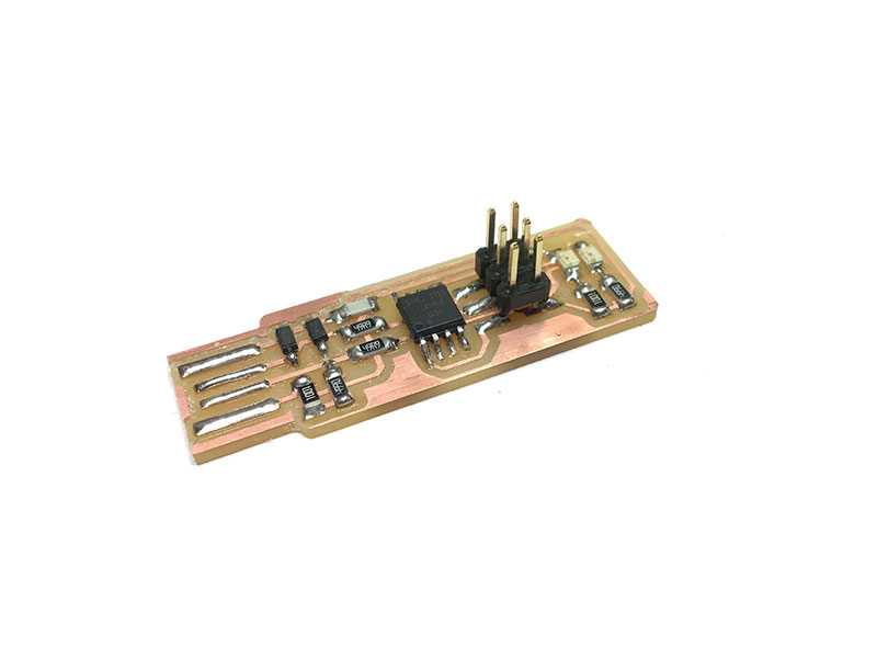
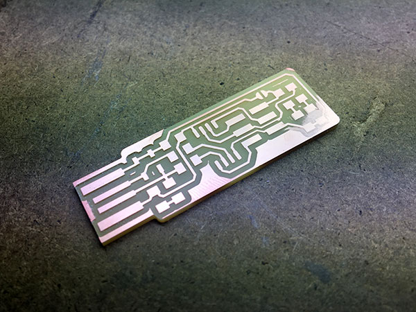 A milled board, ready to solder.
Stuffing the Board
Then I had to solder components onto the PCB (I learned the cool kids call this “stuffing” the board.) I was completely bewildered by what these parts are supposed to do and spent a long time trying to decipher Brian’s electrical diagram and how they related to what I had just fabricated. In the end, I just looked at his photo and tried to match my parts to it (and it worked out fine).
Component List:
• 1x ATtiny45 or ATtiny85
• 2x 1kΩ resistors
• 2x 499Ω resistors
• 2x 49Ω resistors
• 2x 3.3v zener diodes
• 1x red LED
• 1x green LED
• 1x 100nF capacitor
• 1x 2x3 pin header
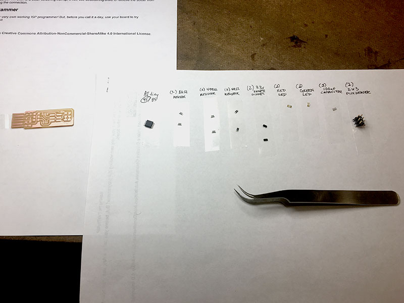 Prepared components. Tweezers and a magnifying lamp are enormously helpful.
Using double sided tape, I laid out all the components on a piece of paper with labels. Then I started to strategize the order in which to solder them. I learned it was best to start from the middle and work your way out. I also learned (the hard way) that LED’s, Diodes, and the ATTiny all have specific orientations. This involved me going through the electrical diagram several times but for simplicity’s sake, I’ve indicated their correct orientation on this specific board below.
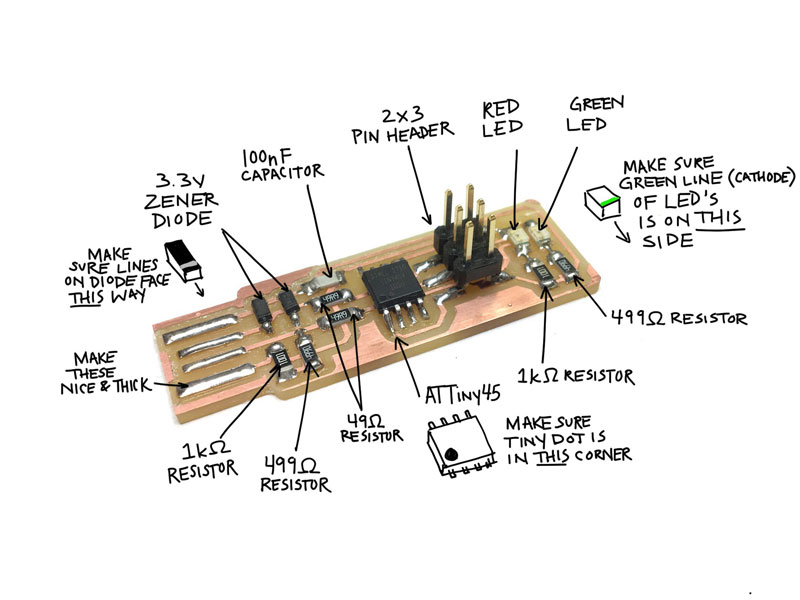 Solder the components to the board. Keep in mind some components have a specific orientation.
Okay, what did I just make?
Milled and soldered and what the heck did I just make? I’ll be honest: I still don’t totally understand what exactly it is but I’m very proud of it.
In the first line of Brian’s page, I learned: FabTinyStar is yet another version of an AVR ISP programmer/board. Okay… I’ve previously used Arduino boards several years ago but I remembered programming them directly from my computer. Doing a little more research I learned that this is normally not the case. Usually to program a microprocessor you need ANOTHER microprocessor called a Programmer which is what we’ve just built. BUT we haven’t programmed it yet. So, I needed to head back to the lab where they had programmer for me to use.
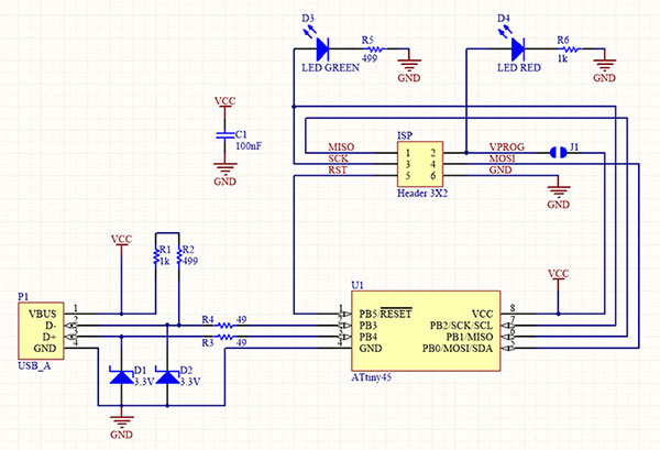 This electronic diagram is somehow the same thing as the board I just milled. Like, every other electrical drawing I’ve ever seen it does not care about physical space.
Programming the Programmer
I downloaded the firmware source code from Brian’s page and brought it to the lab computer. At this point, I should mention again my lack of coding experience and, really, my overall terror at seeing/using any kind of line-by-line code. But it was time to get over that because the next steps involve using the computer’s Terminal (which you can find by going to Start and typing Terminal). Once the terminal opens you have to tell it where to go. You can do this by typing:
cd (The File Extension of your Firmware Folder)
Now that I’m in the right place, I typed in “MAKE” and a new file called “fts_firmware.hex” appeared in my Firmware folder. Now I opened the file called “Makefile” and made sure it was changed to the programmer I was using by changing the lines:
MCU = attiny45
PROGRAMMER ?= atmelice_isp
F_CPU = 16500000UL
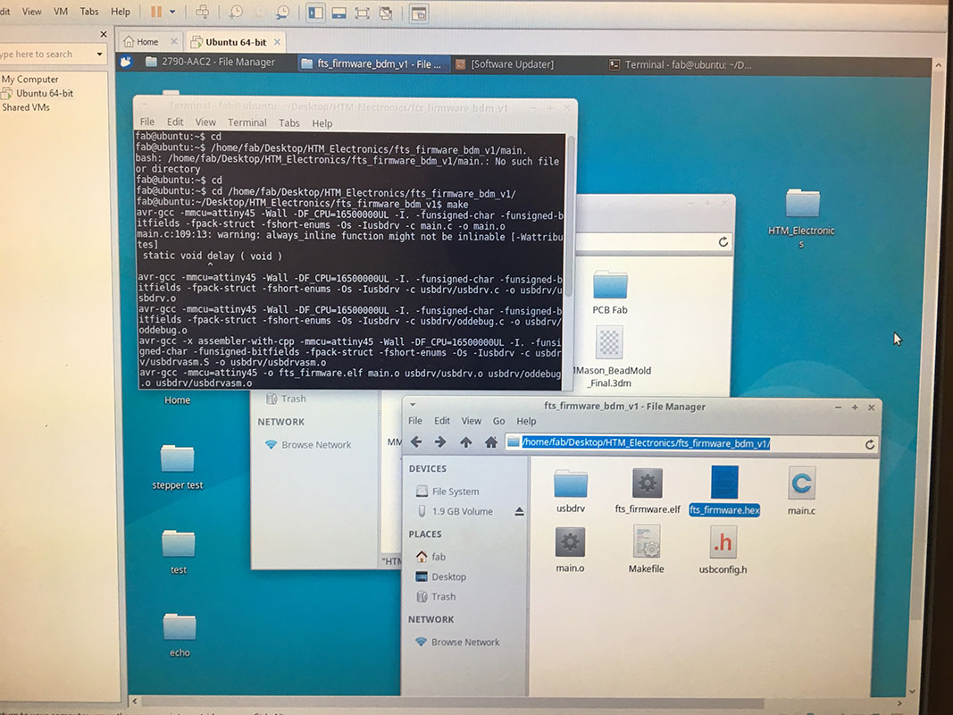 Running the MAKE command will result in a hex file.
Then I connected my board to the computer’s programmer using the 2x3 Head Pin. This will sound dumb but don’t forget to power your board by connecting it to a USB cable (I am saying this because this took me embarrassingly long to figure out). I had to add more solder to the front of my board but, finally, when I plugged it into the USB, the red light turned on.
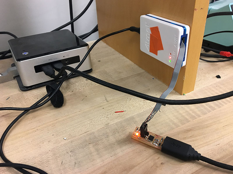 Connect the 2x3 Header to the existing programmer AND power the new programmer through a USB cord.
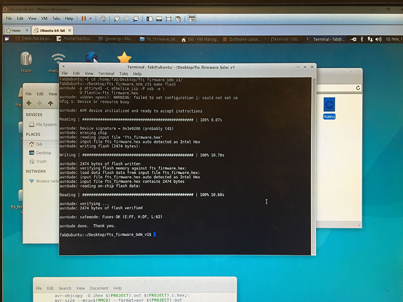
Once connected, I typed MAKE FLASH in the terminal. A bunch of lines of code filled the screen, terminating in one that said I was successful. Then I typed in MAKE FUSES. This sets up all of the fuses except the one that disables the rest pin. Again, I was successful.
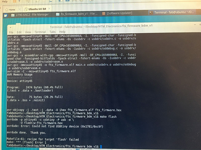 Error from "MAKE FLASH" that might occur if you haven't updated the programmer in your Make File
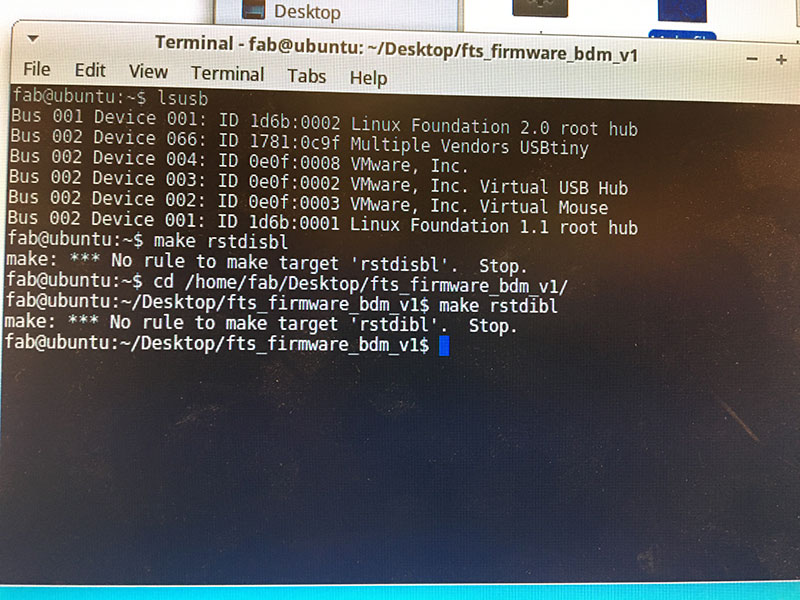
Next, I unplugged my board from the USB and re-plugged it in. I received a notification that the computer found a new device (this is good news). I also typed “lsusb” into the Terminal and found that something that said “Multiple Vendors USBtiny” which means it worked!
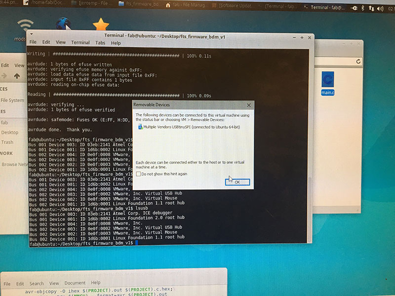 You should get a prompt when you plug the programmer back in
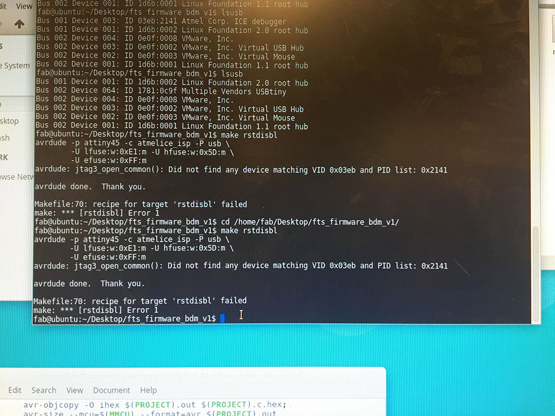
However when I ran the last command RSTDISBL I kept encountering an error. I’m not sure how to fix it and I’m hoping that it means my programmer is still functional (but still capable of being reprogrammed). I plan to remove the solder bridge and test it out later.
Prepare the Development Environment
I skipped this step in Brian’s tutorial because I had access to a lab computer that was already prepared but I want to be able to program directly from my laptop in the future so I came back to it. I’m currently working between a Mac and PC and learned, unfortunately, PC’s take a couple extra steps of prep. You can follow Brian’s Instructions here
Install Git
Install the Atmell GNU Tool Chain (a more direct link is downloading AVR 8-bt Tool chain for Windows from here)
Install GNU Make
Install avrdude
Update your paths
Install drivers for your programmer (I was unable to find USBTiny during this phase- which I'm thinking means I didn't program my programmer after all.)
Files
Visit Brian's Page for Files