week 10
MACHINE DESIGN
How to Drink (Almost) Anything
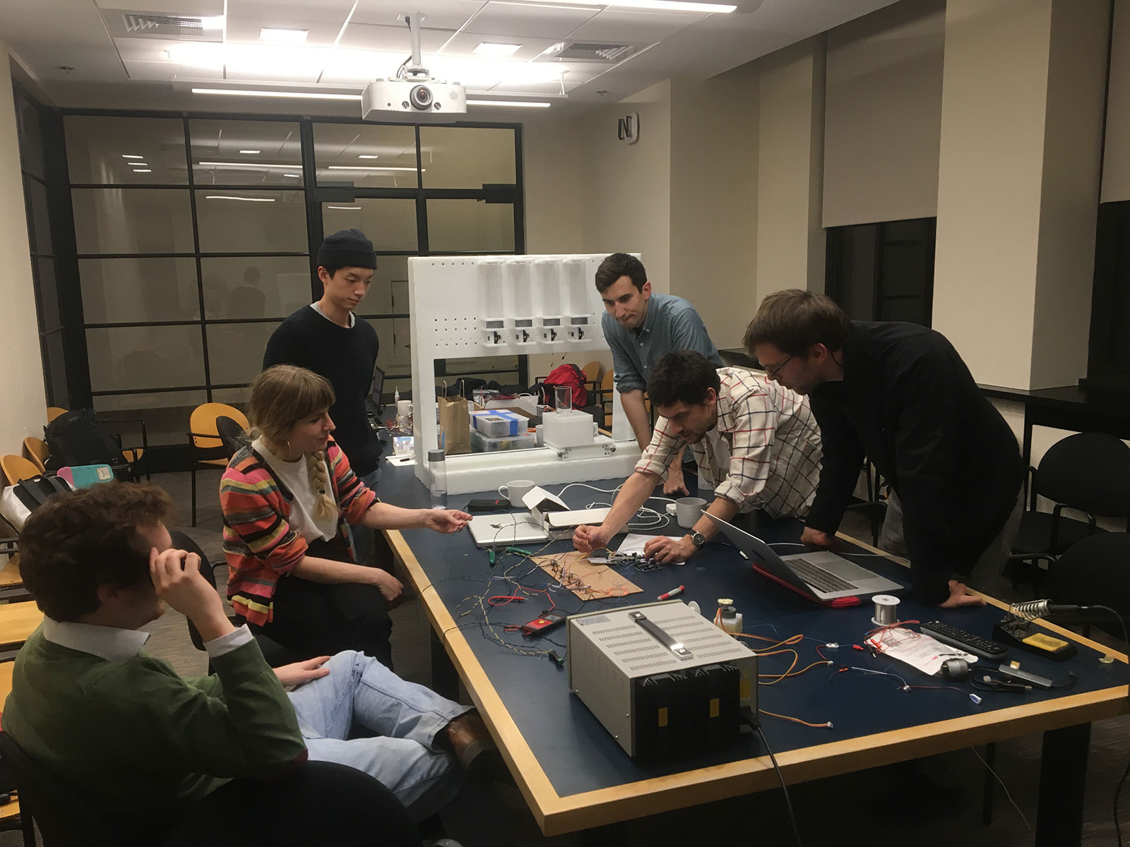
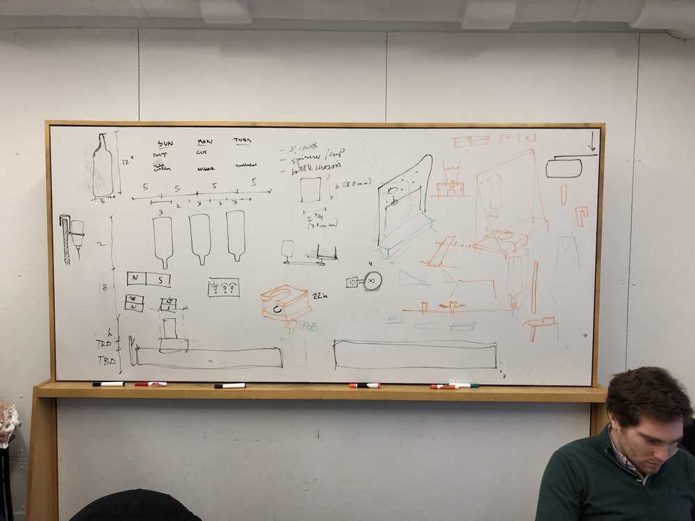
This week we were assigned to make a machine which, defined by Neil Gershenfeld, is just "something that does something." After getting together for some group brain storming, we decided what we all really wanted after weeks of hauntingly persistent rc=-1 messages was a good, stiff drink. And thus, the drink mixing machine was born.
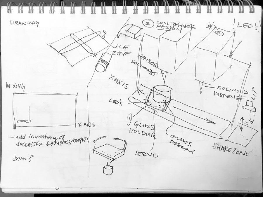
After a design charrette with our team, we settled on trying to make the simplest machine possible – which would be a single axis mechanism that would move a glass underneath bottles that would be able to dispense different kinds of liquids. I was insistent that everything should have LED’s and that we would be able to mix or stir the drink in some way. After some sketches that included having an “Ice Zone” and a “Shake Zone” we decided to incorporate a second motor into the cup holder that would be able to stir our drink.
Chasis + X Axis Team
Design + Fabrication
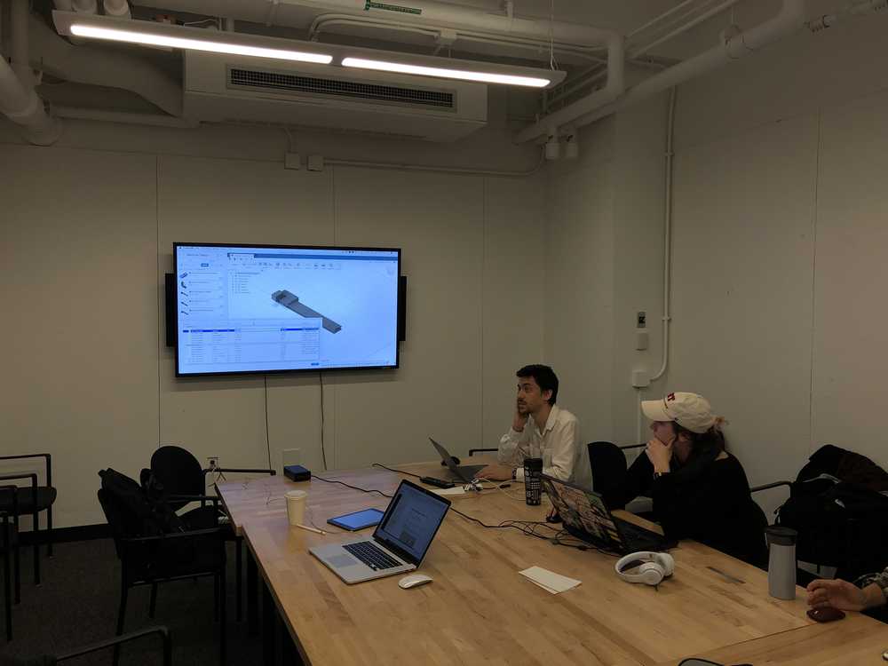
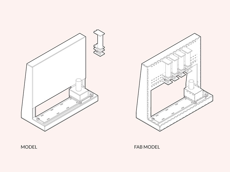
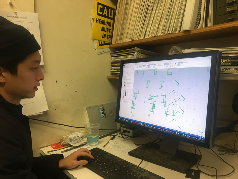
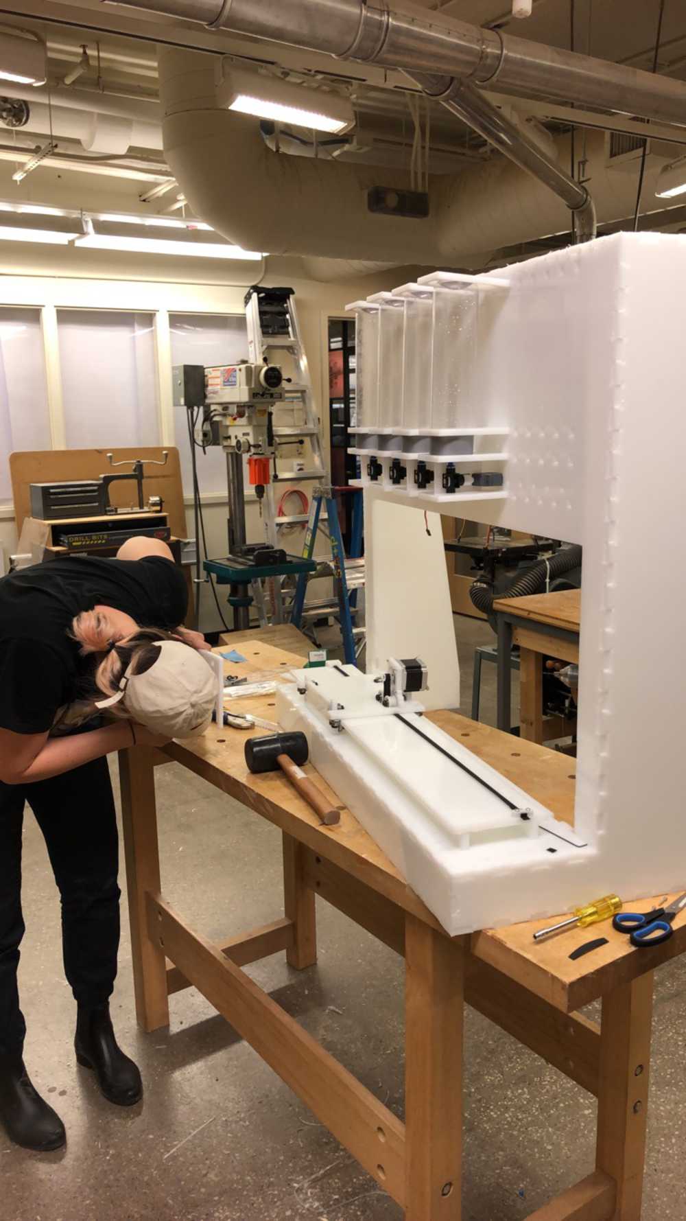
I was on the design and fabrication team of the chassis + X-Axis with Rodrigo, Jim, and Don. We worked together with the group to decide how to make the machine as simple as possible. We took Jake’s helpful gantry Fusion file and combined it with the heights of bottles and areas where we wanted to hide the electronics. I was participating in a workshop this weekend so I had to leave during the actual modeling of the Chassis but Jim passed me the file at the end of the day so I could prepare it for fabrication.
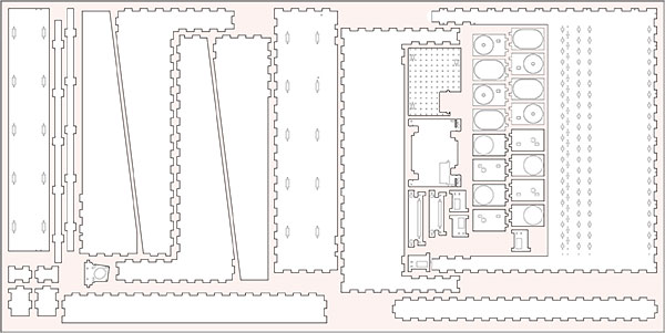
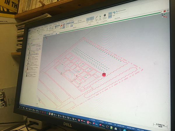
I took a look at the model from last year and noticed their finger joints + screw hole combination was very efficient so I went about specifying the where the fingers would be, simplifying the planes in certain areas, and adding some planes for structural stability. I then began laying out the pieces on a 4x8 sheet, placing points at the corners of any problematic areas (hard lesson learned from Week 07). I then coordinated with the drink dispenser team with where they wanted the place holes for bottle holders.
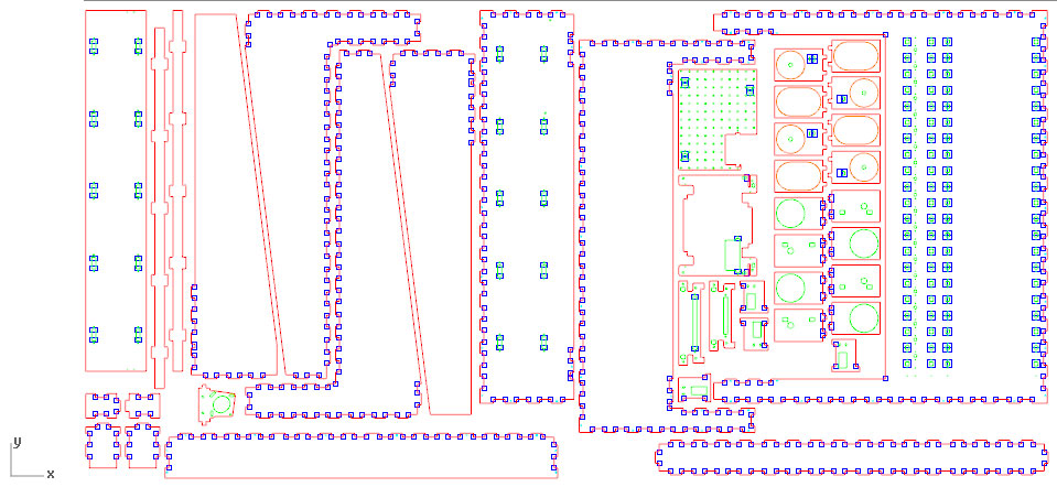
As I laid out our sheet I realized our model was huge! This was okay – we wanted to make it something that actually looked like a bar- but it became a problem when we started to run out of room on the HDPE sheet. Originally we wanted a nice white backdrop behind our drink but I eventually removed it so we would be able to make the bottle holders out of the same material. Finally after coordinating with all the teams one last time, we were ready to mill. Chris Dewart helped up begin setting up a masterCAM file and we were aided by our resident CAM expert, Jung. There were a couple problems with milling – mostly because the bits were a little bit dull but we managed to get all the pieces fabricated.
Assembly
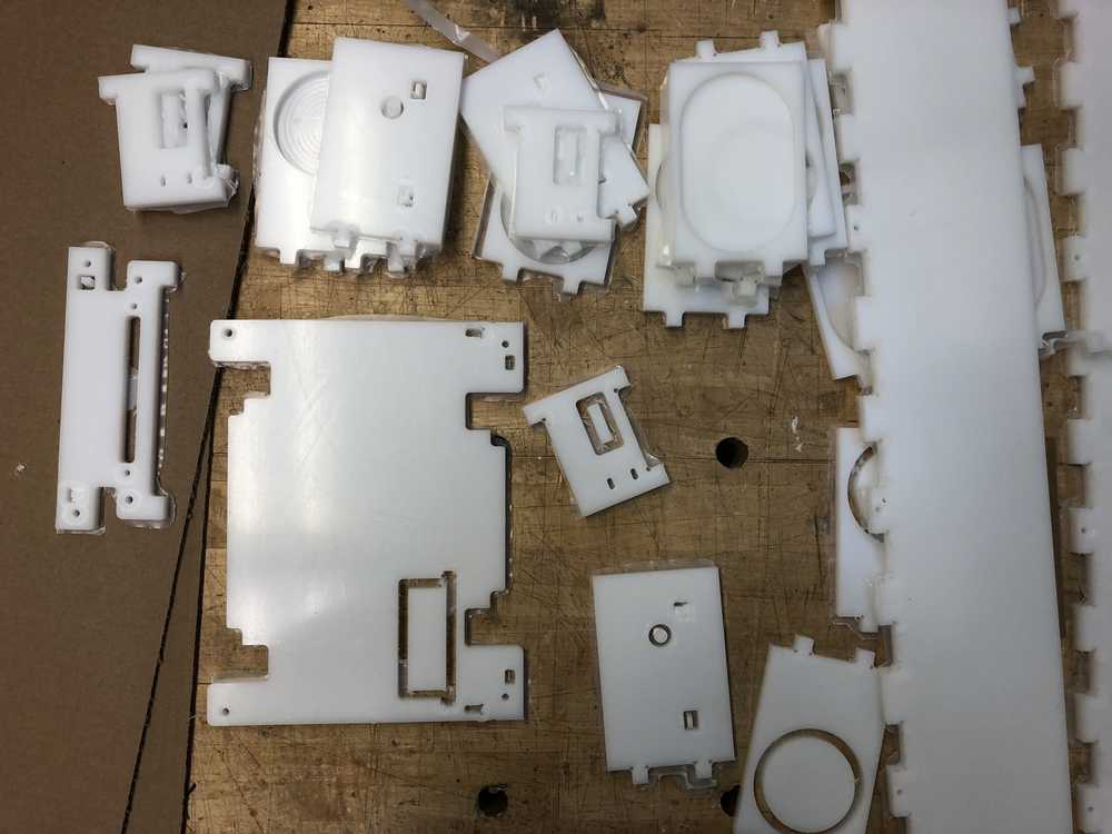
Chris had insisted we do an onion skin because some of our pieces were quite small and while this increased assembly time/aesthetic appearance later, the additional material actually made our pieces quite snug and we didn’t need screws.
Assembly Day
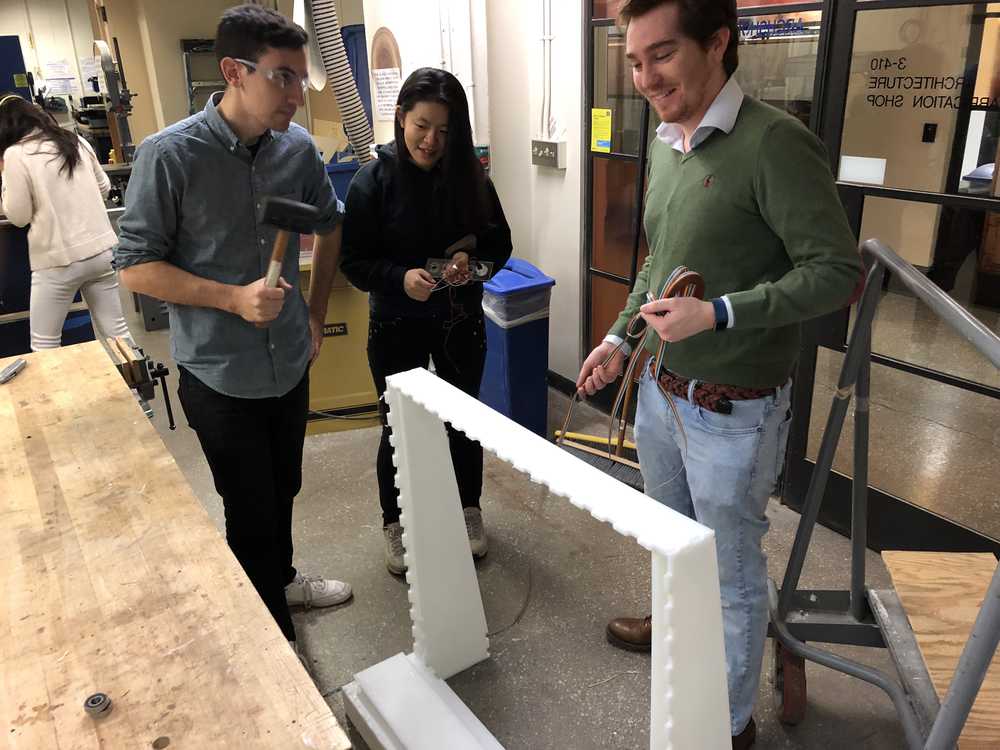
Gantry Assembly + 3D Printing
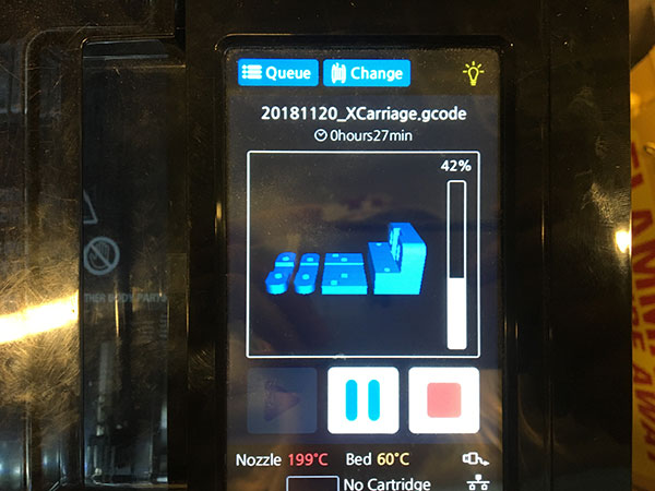
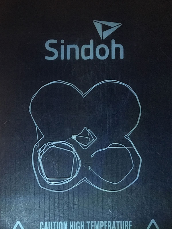
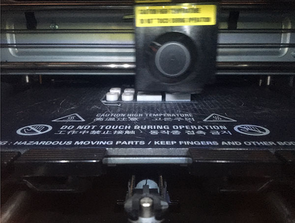
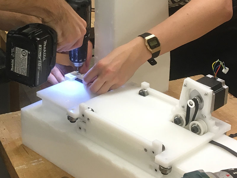
As some of us began assembling the chassis, Don took charge of getting the X-Axis assembled. He quickly realized that none of us had registered that some of the parts had to be 3D printed and I quickly enlisted myself for some speedy 3D modeling to create the belt mechanism anchors and some rings that would ensure the belt stayed in place. All of the pieces were extremely easy to model and (after some intensive surgery on some broken Sindoh 3D printers) were quick to print. The whole process reminded me why 3D printing is such a cool technology. Even with trouble shooting the machines, I was able to make us some key parts within a couple hours.
Jim and I assembled the last bit of the belt. I’ve only worked with belts in loops before and I was little confused about how Jake set up his model. Jim and I also realized that if we added a head to the motor asymmetrically then the whole belt moved in janky steps that were terrible. Jim improvised with some rolled up sandpaper and we were on our way.
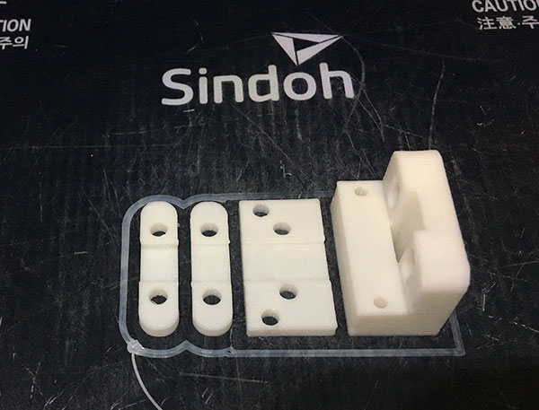
**I set the 3D Print infill setting super low because we were in a rush. If we had more time I would HIGHLY recommend printing with full density. We crushed the belt anchors while we were drilling which meant we couldn’t make adjustments.**
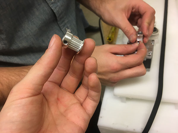
Jim and I assembled the last bit of the gantry. Even though we had Jake’s excellent Roller Coaster Tycoon gantry design, we still had some confusion. Primarily that Jake’s design uses a different belt than I’m used to working with – every belt I’ve worked with is in a loop. Jake’s belt uses two individual strips of belt: a top one (teeth facing down), that is anchored down and allows the stepper motor to move itself along the axis, and a bottom one, that I think is mostly there to provide friction for the top belt. After I totally lost my mind about how belt logics work, we tested how well it moved. Jim and I also realized that the pulley we added to the stepper motor had two set pins which made it anchor asymmetrically. We weren’t sure how to fix this because we didn’t even know a pulley was called a pulley and we DIDN’T THAT JAKE HAD ALREADY PREPARED A 3D PRINT BUSHING FOR US. But it was okay: Jim improvised with some rolled up sandpaper and we were on our way.
The Gantry sliding smoothly along
Cup Holder Design
Since we had run out of EHP sheet space, I realized none of us had actually designed the cup holder. I quickly coordinated with Daniel, who was working on the motor and LED’s, and came up with a design that would allow us to hide the electronics. We used the laser cutter and a hot glue gun to quickly rig it into place. While this was happening, Jim and Daniel managed to get the stirrer to work and even though I didn’t work on any of the electronics for it, I’m including it here because it’s my favorite part.
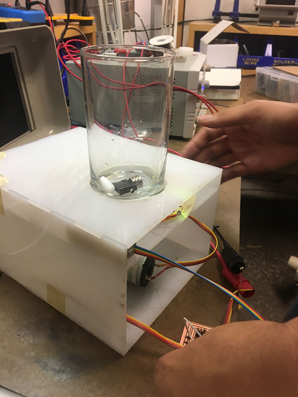
V cool whirlpool
![]()
Finale
The final hours before our deadline consisted of all us sitting in the same room as we ate pizza and watched/tried to help hook up all the electronics. Those of us not programming worked on quickly setting up the website for class. Unfortunately, I had to catch a 4 am flight the next morning so I had to leave before we completed all the programming. I stayed long enough to see each part of the machine work.
X Axis Cup Movement
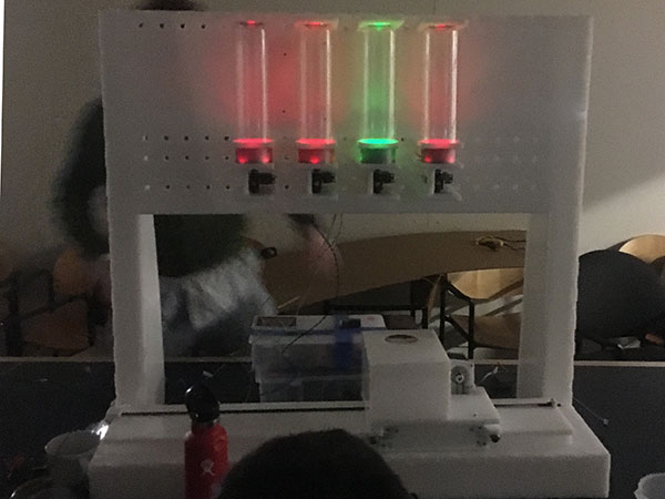
Drink Dispensers
The Stir Zone
Even though someone texted me the next day to tell me the stepper motor had burned out (because we were using Arduino boards), I had a lot of fun working on this and this was probably my favorite project in this class so far. My contributions to this project were primarily design, fabrication, and coordination although I think my proposal to design a drink called “rc=-1” was probably most helpful. It would consist of 2 parts absinthe, 3 parts battery acid, with a garnish of dried sweat from MIT students.