week 09
OUTPUT DEVICES
Tools + Methods
Roland Modela Mill
Soldering
Arduino IDE
This week we needed to hook up an output to our boards. I’m still debating the mechanism of my final project but it’s either going to be a motor or some kind of air pump. I decided on making a motor since it seems more versatile. I chose to use a DC motor because I have a feeling a servo won’t be able to handle the kind of torque I’ll need in my final project.
Board Design
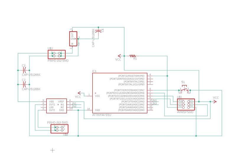
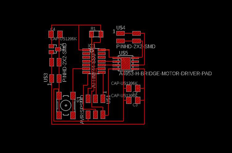
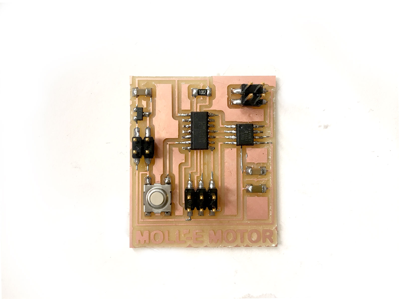
I started with the hello.H-bridge board for a DC Motor with the intention to try both a DC motor and vibrating 3V DC vibrating motor (not at the same time). The board was more intense than last week’s Sonar. We needed the usual ATTiny44, 2x3 Header, Pull up resistor, and capacitors but also needed IC2 5V Power Regulator, a 2x2 Header Pin for power to go to, another 2x2 header to go to the motors, and an H Bridge – which will allow our DC motor to run forwards and backwards. I also added a button to my board so I could test how the board would handle input driven out puts (I wanted to make a more dynamic sensor that would rotate based on the proximity detected from a Sonar but if I’ve learned anything from the past couple weeks of horror, it’s best to verify these things one at a time).
Making the Board
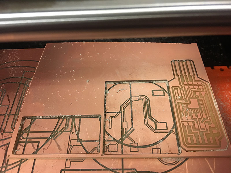
I'm beginning to get the hang of fabricating boards. This week I wanted to remake my board from last week, cut my new board, and cut a FTDI Board so that I don't have to keep going to the lab to program my boards. I reached a truly olympic level of fitting my boards on the minimum amount of copper sheeting and I've documented it here for posterity.
Stuffing the board went fine. I tried out the new "reflow" technique for the ATTiny's millipede of legs. First I laid a little solder down on each pad the I added a little solder to the foot of the AT. Then using heat gun, held the ATTiny in place until the solder on the pads was hot enough to merge with the solder on the feet. This didn't work out super great but I'll probably keep practicing.
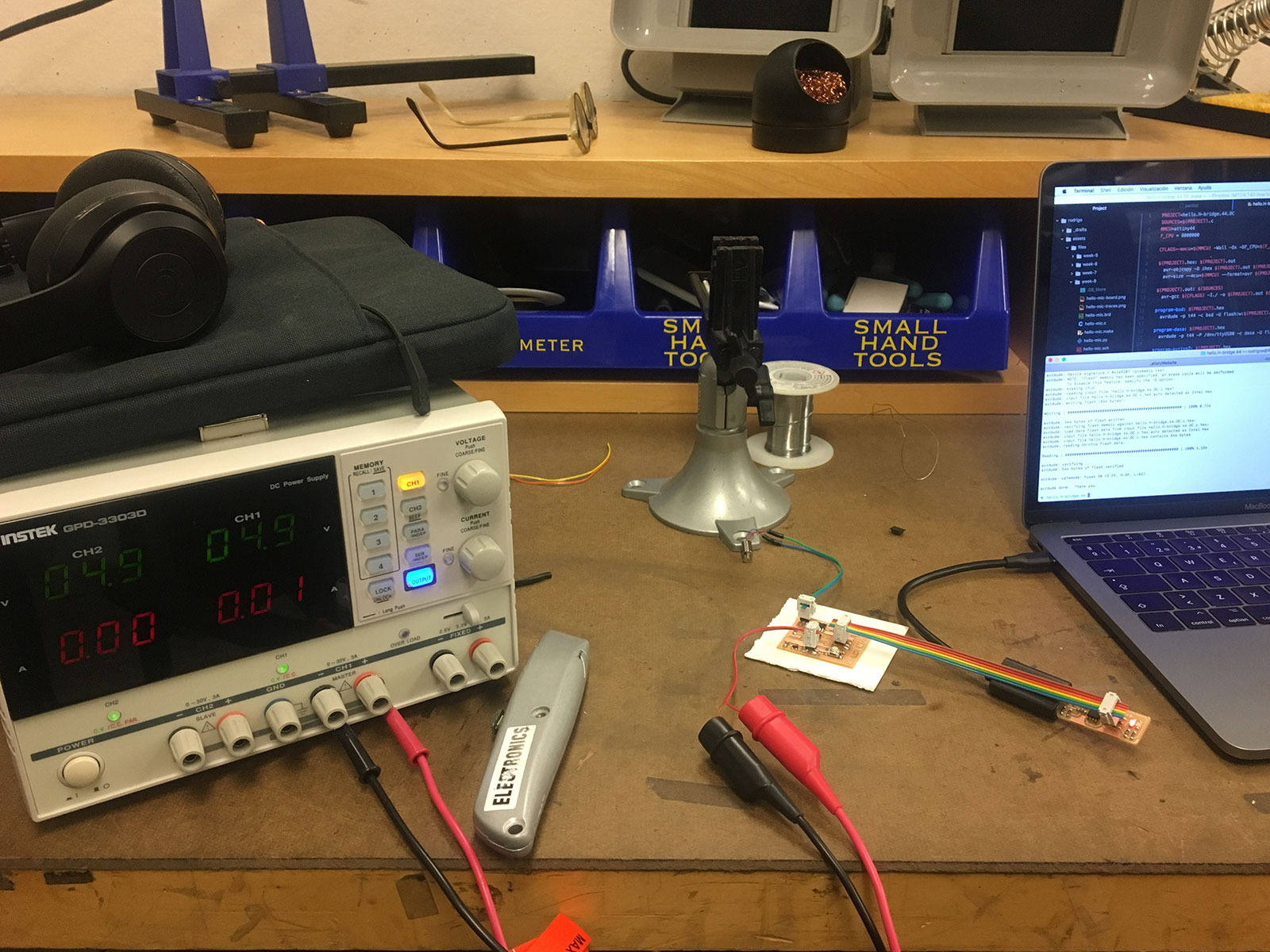
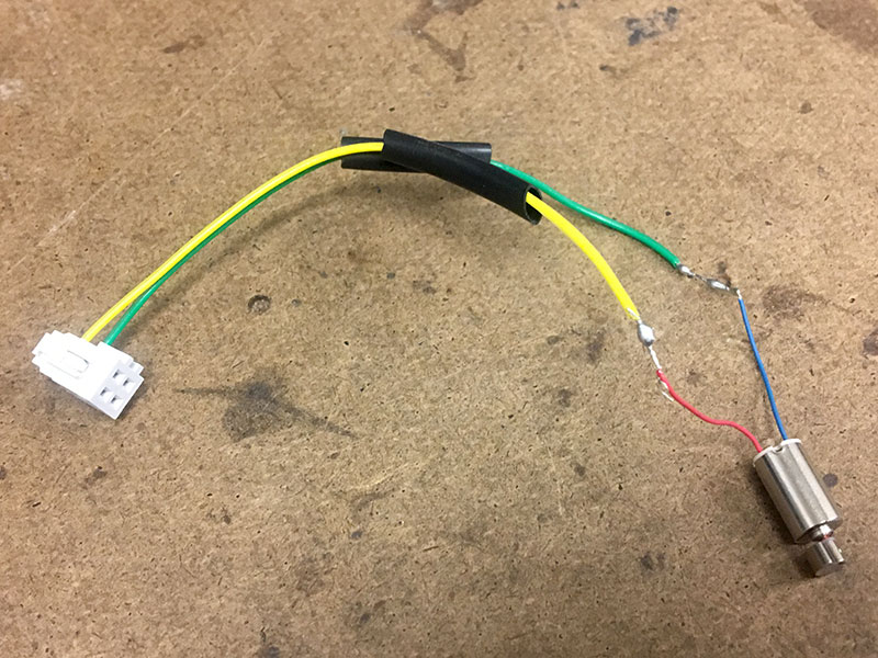
Hooking up the motors required a new kind of wiring. I ripped up some rainbow cable until it was only 4 wires wide. Then I cut half of two of them off. (I am doing this because the header I'm using is intended for four wires but I'm making do with it). I then stripped the tips of the two remaining wires. Using the exposed wires, I soldered them to the two wires coming out of the Vibrating DC Motor, keeping in mind which ones where power and ground (GND=Black, VCC=Red). Then I cut tubes of a heat shrinking material, covered the exposed wire bits, and used a heat gun to shrink it down to size. Now the motor is ready to conect to the board. I still need power though so I headed to the lab to use their power supply, powering it up to 5V.
![]()
Programming the Board
Arduino
Although I don't understand C, I originally tried just running Neil's make file to see if I could get the board to work. It didn't work so I returned to Arduino where I have a slightly better understanding. I had a classmate explain bootloaders to me last week- basically, if you don't burn the bootloaders to your Arduino board then you're board is running on the wrong clock (or something like that). I went to burn the bootloaders but was hit back with the following error:
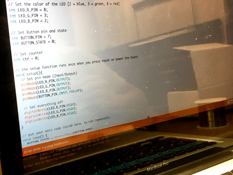
I was struck repeatedly with rc=-1 when I tried to upload a common Blink code. How could life be so cruel? I need to remake the board, I think, but I don't have any more time this week./p>
Files
Traces
Code