week 06
EMBEDDED PROGRAMMING
Tools + Methods
Roland Modela Mill
Soldering
USB Tiny Programmer
This week we were supposed to actually program the board we made to do something. Which meant, it was time to read the data sheet. Which meant: the jig is up. Time to actually try and learn some of this electronics stuff.
Programming the USB Tiny
I had to go back to Week 02 to actually program my programmer. This was a frustrating process of trial and error that took WEEKS to resolve so I will summarize the many errors and resolutions as best I can below. I’ll start by saying how it ended: I ran into an insane number of problems on the lab computers then, doing the exact same thing I had been doing in the lab, I was able to program my board on a friend’s Mac using their USBTiny.
First, I went back and reread Brian’s tutorial which is actually starting to make sense to me at this point. I went to the labs to use their computer and programmer, an Atmel ICE. The lab uses a Virtual Machine which runs on Ubuntu. Open the VM and then make sure that the programmer can be found in the VM (also make sure the programmer is plugged in via USB). You can verify this by going to the top toolbar VM>Devices>Atmel>Connect Device. You can also connect your programmer-to-be’s header pins to the existing programmer’s header pins using a rainbow cable (which you can make yourself in the lab). If everything is connected and soldered right your programmer’s red LED should light up. Yay!
*Mistake 01: Sounds dumb but sure you’re powering your USBTiny. You should have it connected to a USB cable (where the four lines are) AND connect the header to the programmer you are using. The red light on your USB Tiny should turn on.
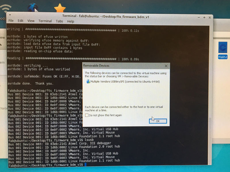
*Mistake 02: Make sure that your USB is connecting to the VM and not the Windows Computer. You can do this by going to VM>Devices
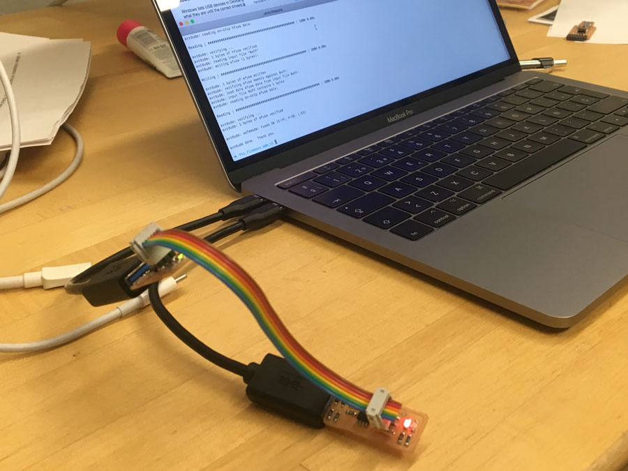
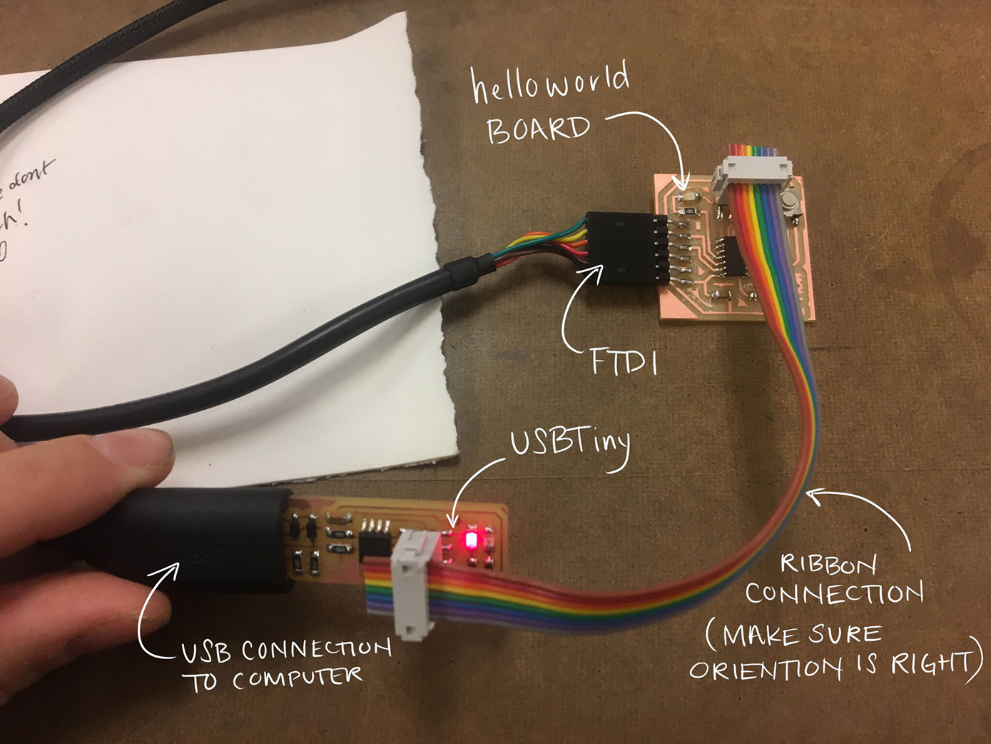
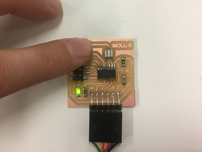
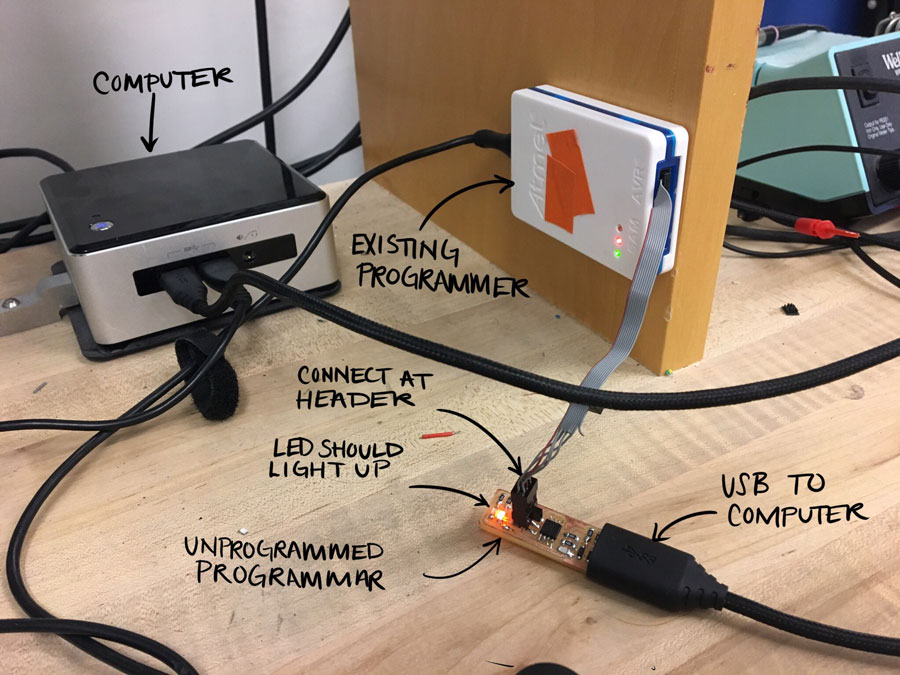 The set up for programming the USBTiny.
Great. Now download the firmware source code from Brian’s page. You should get a folder with several files in it. Save this somewhere where you’ll know how to find it. Now, open the Terminal on your computer. Type
cd [path to your files]
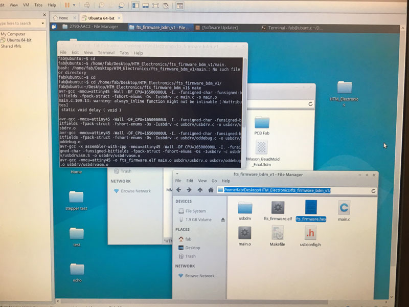 A successful "make" command
This will direct the terminal to your directory. Then type “make” into terminal. If you return to your firmware folder you can see a .hex file appear. This is a file that your programmer can actually talk to but we don’t have to interface with it. At this point, open the “Makefile” with a good editor (Notepad++ for Windows, TextEdit in OS X, gedit in Linux) and scroll down to the part that says “Programmer ?”. This needs to be changed to whatever programmer you’re using. In the Lab, we used “amtelice+isp” (although later I was able to program via USBTiny so I didn’t change this file).
MCU = attiny45
PROGRAMMER ?= atmelice_isp
F_CPU = 16500000UL
This is where my problems started:
Trial 01
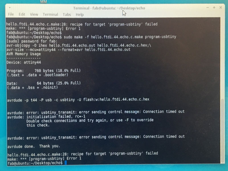
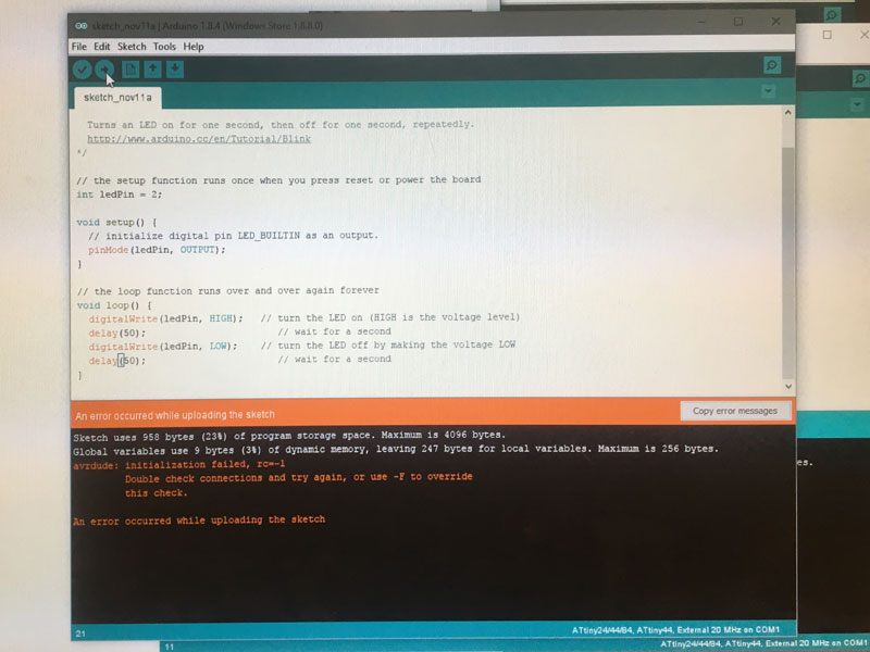
After editing the makefile I ran the “make flash”. The first computer hit me back with this error message.
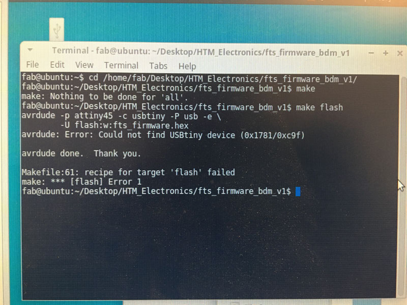 Error when running "make flash"
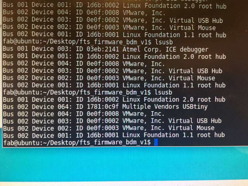
For some reason, this file didn’t work on one lab computer but DID on the other. I have no idea why because I think they both use the same programmer. (I later suspected that it was because one of the cables was faulty). When I ran it on another computer I was able to run “make flash” and “make fuses” successfully. Then I unplugged my USBTiny and replugged it. I typed “lsusb” into the terminal and sure enough “Multiple Vendor USBTiny” showed up!
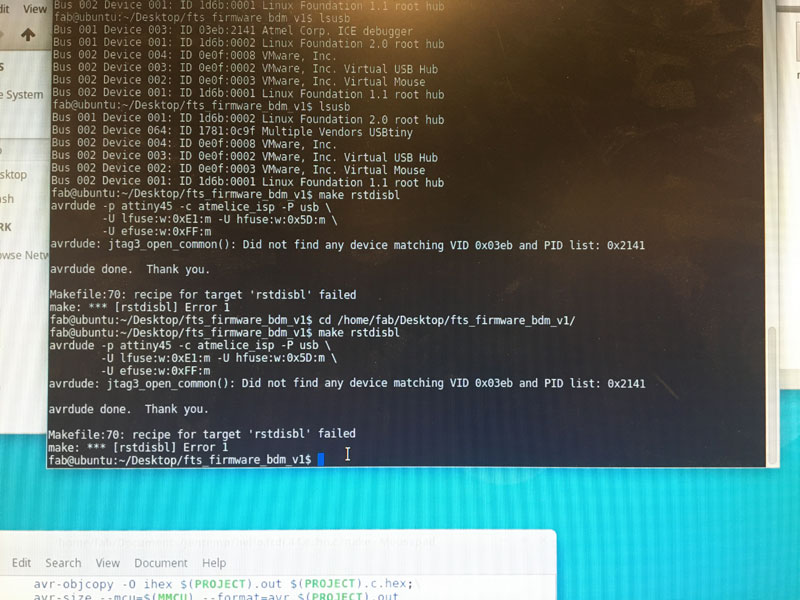
Even though everything seemed to be set up correctly, when it came time to rstdisbl something went wrong.
Later, I thought maybe I had programmed it after all. I tried to hook it up to my hello-world board. It did not work. Then everytime I went to program it again, it resulted in an rc=-1. I checked the board and it look good. WHY WAS EVERYTHING GOING WRONG?
Our TA Ben listed the possible causes of rc=-1
- Programming cable is oriented correctly. (A Brian-pattern FabTiny will light up bright red if connected correctly, and dim red if connected incorrectly.)
- Board is milled correctly (traces are properly isolated).
- No shorts between power and/or data lines.
- No open circuits between t44 pins and corresponding connector pins.
- Solder joints are in good condition.
- No unintended solder bridges between adjacent pins / traces.
- t44 is oriented correctly on board (check pin 1 indicator).
- Required clock source is present on board (depending on how you set fuses) and in good condition
- No swapped data signals. (For instance, verify that MOSI goes to MOSI and MISO goes to MISO.)
- Programmer is in good condition (does it talk to a known-good board? if FabTiny, did you make rstdisbl?).
- Computer is in good condition (does switching computers produce a different result?).
If all else fails, mill a new board.
Trial 02
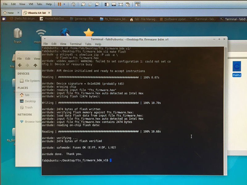
I was willing to admit my soldering might not be up to par. I remilled and soldered a new board. I checked the computer again: SAME RESULT. At this point, I ran into a classmate who noticed my distress. He offered to try programming it on his computer (a Mac). We hooked up his USBTiny and my potential USBTiny via USB cords and header connections. We made sure the computer could find his USBTiny. Then we opened the terminal and ran ‘make flash’ (I brought my previous files with me on USB) and this time IT WORKED. We typed “make fuses” and it also looked like it worked! Then it was time to check that the computer recognized the new USBTiny. I unplugged my USBTiny and then replugged it. Then I went to the terminal and typed “lsusb” and sure enough “Multiple Vendors USBTiny” device showed up! Lastly, we ran rstdisbl and it also worked!
In the end, I was torn between being happy my programmer was finally working and furious because doing the same thing on different computer had fixed everything and I wasn’t able to pinpoint the point of failure. I think there was a possibility that the cord connecting the Atmel Programmer in the lab might have something wrong with it and THAT was why I had the rc=-1 problem.
Programming the Hello World Board
Originally I wasn’t able to resolve my programmer problems but needed to move ahead with programming. I borrowed a friend’s programmer which I knew to be working so that I could try programming my Hello World board (this is a great way of at least isolating which one of your boards isn’t working). Unfortunately, my hello-world board had problems too! I used a multimeter to diagnose that the voltage was correct from VCC to Ground (5V). Axel took a look at my board and said there might be some miswiring problems- mostly that I had wired my button so that it stopped the LED from communicating directly with my ATTiny. He also pointed out that I was missing two ground traces. I tried very hard to do surgery on it but had a lot of difficulty. I decided to remake my board with better traces and see if I could get this thing to work.
I decided to draw and fabricate a new Hello World board from scratch. After some frustrating fabrication errors which I have added to my Week 04 page, it was time to test again. I started by following the high-low tech tutorial. At first, using my programmer, I was weirded out because, after unsoldering the bridge, the little red light wouldn’t turn on anymore. I realized this is normal. Your programmer no longer lights up when plugged into a USB but WILL light up when connected to the Hello World board by the header pins (the hello board should be plugged in to a FTDI (which you can make yourself here!).
Then I opened the Arduino IDE and followed the tutorials steps on adding additional board mangers. Then I was able to go into Tools and change the board to ATtiny45, the process to ATtiny 45, the Clock to External 20 Mhz (because my board has 20MHz resonator), and the Programmer to “USBtinyISP”. I opened the Blink Sketch which you can actually get directly out of the Arduino IDE by going to File>Examples>Blink.
It was time to get another rc=-1 response. I borrowed a different friend’s programmer so I could isolate whether the problem was my board or my programmer. I received another rc=-1. I checked my board with the multimeter. It seemed to be conducting power (but maybe I wasn’t checking in the right places). I visually inspected my board – the solder joints looked good but I decided to add some more solder to the header and FTDI joints because I wasn’t sure what else to do. I thickened the solder on the ATTiny, FTDI, and header. Then I tried again – and to my surprise, it UPLOADED WITHOUT ERROR.
But the LED still wasn’t lighting up. I looked at my Arduino Code. I had inserted the ledPin= 11. This is because it was connected to the 11 Port in the ATTiny. I switched to the Blink File (one problem at a time). Then out of sheer desperation, I just tried changing the ledPin to every number starting with 0. Then when I switched it to 2 something magical happened. A SWEET GREEN RADIANCE OF SOMETHING NOT GOING TERRIBLY WRONG. I was able to change the blink time and make it quickly blink. I WAS NOT A FAILURE.
int led = 13;

void setup() {

  pinMode(led, OUTPUT);
}

void loop() {
  digitalWrite(led, HIGH);
  delay(1000);
  digitalWrite(led, LOW);
  delay(1000);
}
Then I moved on to the Button Sketch which you can also get from the Arduino IDE through File>Exampes>Digital>Button. I changed the ledPin to 2. And tried a ButtonPin = 8. AND IT WORKED. Kind of. My button barely had to be touched to turn the LED on. And sometimes just turning the board made the LED turn on. Maybe I had soldered my button incorrectly afterall.
Due to complications this week, I wasn’t able to expand my hello-world board. My next steps are:
- Make a board with a working button.
- Make a board with multiple LED’s
Files
See above Arduino Sketch