Computer-controlled cutting
This week we learnt our first two computer-controlled cutting techniques: the vinyl- and the laser cutters. For the group assignment, we had to characterize our lasercutter (i.e. make test parts varying cutting settings and simensions.). Then, individually, we had to (1) design and lasercut a parametric press-fit construction kit; and (2) cut something with the vinylcutter
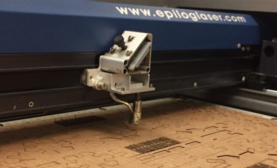
Lasercutter
In order to characterize our lasercutter (power, speed, frequency, account for kerf,focuss, etc.) my group designed a template in Rhino. This basically consists on a rectangle with different slot sizes (since our carboard is 0.25" thick, we cut slots ranging from 0.235" to 0.245"). We found that 30% speed, 30% power and frequency of 500 gave optimal results. Slots drawn with 0.240" worked the best for press-fit purposes [Note that cardboard ~0.25", kerf ~0.05]."
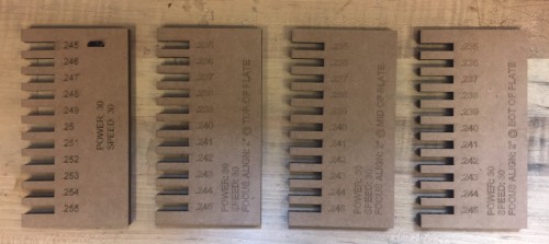
We cut different slot sizes in order to find the best for press-fit constructions. We played with power, speed, frequency and focuss distance.
As for the individual assignment, we were asked to "... design, lasercut, and document a parametric press-fit construction kit, accounting for the lasercutter kerf, which can be assembled in multiple ways." So here we go:
A few weeks ago, I entered in a toy store in Coolidge Corner and found a series of super cool press-fit mechanical model kits. I thought about doing something like that, but those kits cannot be assembled in multiple ways, so I decided to leave that as part of a potential final project and go much much simplier (for now)
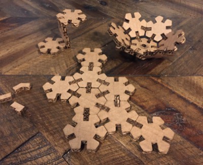
So, I considered regular polygonal geometries that can be easily assembled. The obvious choice was the triangle, but I wanted something more complicated so I chose the hexagon (triangle x 2). I used Fusion 360 for my parametric design. I started with 1"-side hexagons, placing a slot (0.240"x0.375") on the center of each side. I also chanfered the slots to facilitate the assembly process.
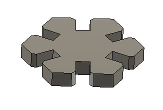
Press-fit kit basic unit.
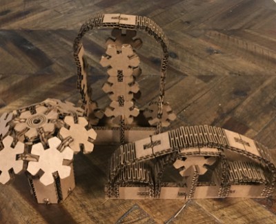
After I got some practice with parametric design, I started to think in new shapes: rectangles, pin connections at different angles (60º, 90º and 180º), and flexures. The rectangles and pin connections were relatively straightforward. For the flextures I had to experiment a little bit (initially simply by cutting parallel lines, then small windows). But at the end I got with an optimal window -size and -separation.
Once I finalized the design, I transfered the drawings into AutoCAD, arranged the layout, and ready to lasercut. Special attention was paid to the orientation of the pin connectors relative to the direction of the corrugates (if they happen to be aligned, the pins won't resist compression!). I used 28% speed (slightly lower than before in order to facilitate the cuttings separation), 30% power and 500 frequency.
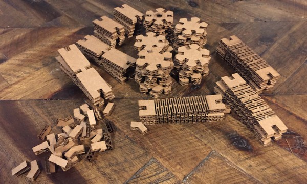
Then I added new components: rectangles, pin connections, and flexures.
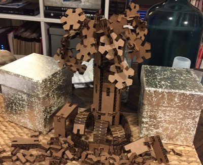
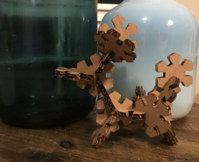
Finally, I got some time to play with my new toy and build different "sculptures":

Vinylcutter
For this part of the assigment, I wanted to be original, so I decided to print a sticker for my laptop (...). I have a MacBook and (of course) whatever I printed had to "interact" with the logo. I saw very cool designs in google, but I felt I should actually do something more personal. I'm from Spain, and I thought something from there could be cool (e.g. a monument, an animal, ...).
I liked the idea of cutting an iberian lynx (which btw, it's the world's most endangered feline species). I started by googling pics of a lynx, imported them into AutoCAD to draw the contour (I know...), and then fill them and generate the png image. Here is the result:
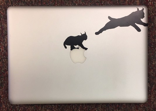
I'm pretty happy with the outcome. Specially, with the lynx on top of the apple (the other one has some bubbles I cannot eliminate...). Now I'm thinking on printing some more...