Mechanical machine design
The task for this week is to design a machine that includes mechanism + actuation + automation. After some brain storming, we decided to build a bartender machine! We are documenting the whole group project here. I'll use this page to describe my individual contribution.
Electronics and programming: Lukas, Daniel, Yi and myself
Our machine will consist of a single x-axis which would move a cup under four different bottles which would dispense the liquid. In addition, we will also install a bunch of LEDs, and a magnetic stirrer that will be mixing the drink during the whole process. So, we need the following:
We planned to make it as modular as possible, so we could troubleshoot individual parts and then combine them. We played a little bit with Jake's boards... but didn't underterand them completely, so we decided to make our own (this will turn out to be a bad decission...). The basic idea was that we will be using an Arduino board for central control, and send digital commands (i.e. HIGH/LOW signals) to activate the other boards controlling the peripherals. I got in charge of the fluid dispensers.
Fluid dispensers
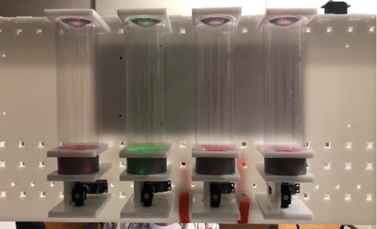
The mechanical team decided to use a sort of manual ball valve to control the amount of liquid dispensed. So we basically had to turn a the handle 90 degrees in oder to open/close it. We incorporated a servo motor to the job (for each serving station). In addition, we added an array of RGB LEDS to each station to enhanced the visual effect (e.g. change the color when the liquid is being poored, blink, etc.).
In order to reduce the amount of wiring (e.g. power, digital signals) I designed a single big board. This was a big mistake: (1) it took FOREVER to mill, (2) FOREVER is a long time, with more chances for errors to happen... When the board was ~90% completed, the endmill broke, and we lost everything...
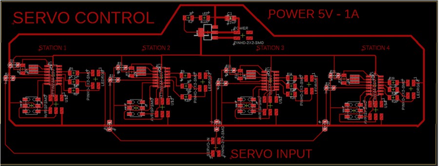
Liquid dispenser (BIG) control board
Given the amount of time it took, and the fact that I couldn't guarantee success, I decided to subdivide the big board into four small ones. Each one is powered individually from the power supply, controls one servo, has one input pin (to receive signals from the Arduino) and thee outputs to control the RGB LEDs. Here are the schematic and the traces.
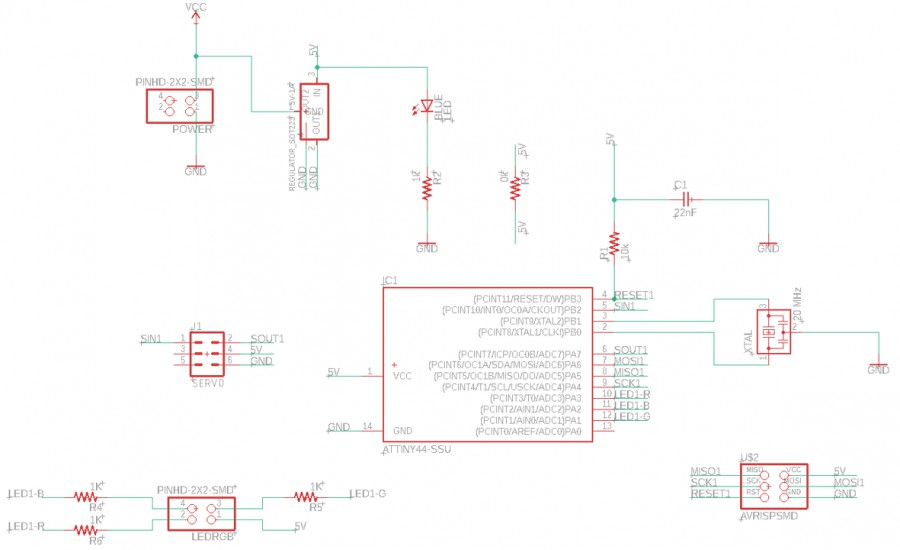
Fluid dispenser (1 station) - Schematic
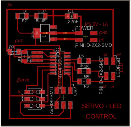
Fluid dispenser (1 station) - Traces
For the programming, I used Arduino IDE. Since I did similar things during the Embedded programming-and Output device weeks, this particular task was not very difficut. I attach my codes at the end of the page.
Powering the system + Integration
After I tested the individual boards, it was time for integration. Our boards required different voltages: 5V (Arduino, Fluid dispenser), 12V (Magnetic stirrer) and 24V (x-axis). Instead of using Jake's AC/DC power supply and coverting from 24V to 12V and 5V, we used one of the 3-channels power supply we had in the shop. This way (which was simplier) we could share the same ground among all components.
The integration between the Servo-boards (fluid dispensers) and the Arduino was simple. We run the same GND to every board and found no problem. The issues came wheh we connected the boards which worked at a different voltage ...
We don't know what failed... keep working until 5am... nothing :(
Files