Electronics design
This has been a very long week (with a lot of of learning too). We were asked to (1) redraw the echo hello-world board, (2) add a button and a LED, (3) check the design rules, (4) make it, and (5) test it. It's a lot, so let's start from the beginning.
Mastering Eagle
In the past, I had done some work with electronics (soldering connectors, sensors, motor controllers, simple signal aplification, etc.). But I had never ("professionally") drawn a circuit, neither had an strong base on electronics component, or done embedded programing (besides week 3). SO, in addition to last/this week recitations, I started with some (fun) reading:
The tutorials above (recommeded by Jake) were super hepful. It took a while, but after finishing with them I was able to read an schematic, to draw my own, and to route a PCB!
Understanding the echo hello-world board
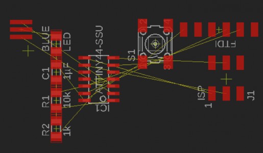
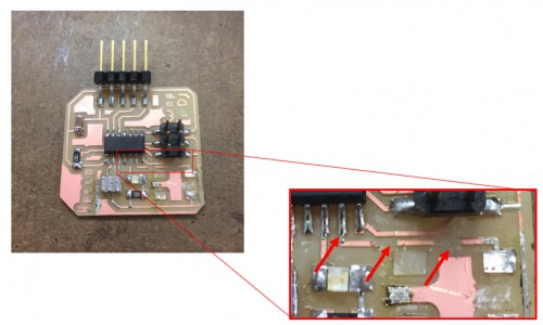
So, I got all these new skills with EAGLE, but at this point I was not sure what to do with them. My next step was to look at Neil's (and other people's) diagrams to decode what is in the "standard" echo hello-world board. The image below shows a board -picture and -diagram, and identifies all the components:
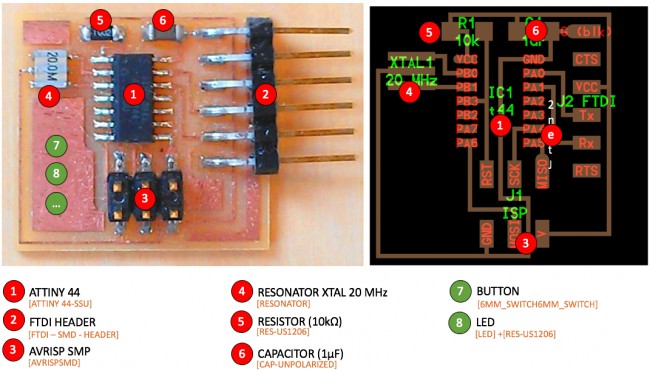
Echo Hello-Worl board: components. The names inside the brackets refer to the EAGLE library' ones.
I quickly reviewed the ATtiny44 specs sheet, but I'm still a little but confused why we need the resistor/capacitor in the circuit... Anyway, at least I know where/how to connect them.
In addition to the components above, we were asked to add an LED (+ corresponding resistor, in my case I chose 1kΩ) and a button, as shown in the next sections.
Redrawing the echo hello-world board
Once I identified all the components and corresponding connections (and finished the EAGLE tutorials), I was ready to start with my board schematic. I used the add command to include them in my work space:
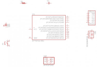
I started with the layout of the electronic components
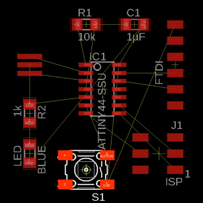
Then, I organized them (move, group and copy commands were handy) and started to draw the connections using the net and name tools (the latter was very useful to keep everything organized, avoiding too many wires). When I finished, I used the show and erc commands to check for errors/warnigns in the connections.
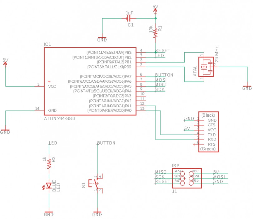
Echo Hello-World: Schematic. I added a LED and a resistor (to pin PB2), and a button (to pin PA7).
When I switched to the board view, everything was a little bit messy:
EAGLE: board view.
I moved things around, tried to minimize connection crossings, displayed the grid, and used the rat command to redraw the connections after moving components:
Now it looks more organized
For the routing process, besides the route/ripup tools, I really liked show. This command allows you to highlight a specific net (e.g. GND or VCC). For the traces I used a width of 12 mills, and the provided DRC rules. I had to move things around a little bit... and at the end...
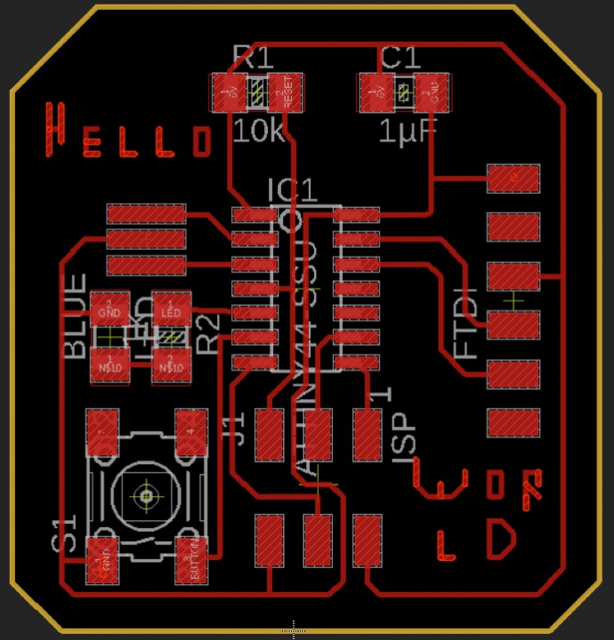
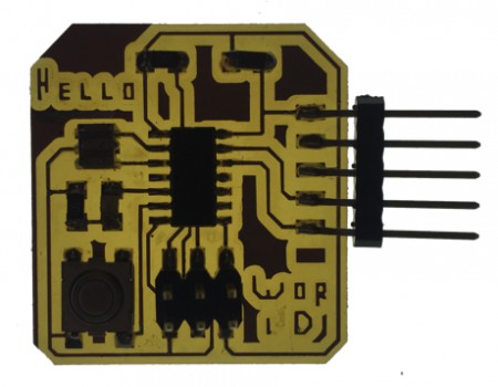
... I got I nice board layout. I even used the wire tool to add some text.
Finally, I used the ratsnet and DRC commands to check for missing connections. In order to export my board to .PNG, I used the following commands:
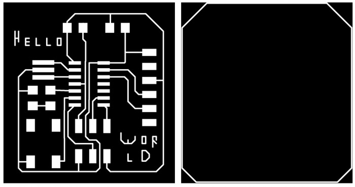
Traces and outline ready to be milled!
Milling and stuffing the board
Not much to say here. I followed the same steps (same settings, same everything) as in week 3. However, one note for the future: mods → programs → open server program → Roland → SRM-20 → PCB. Here it is the result:
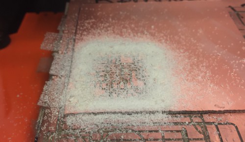
Milling with the Roland SRM-20...
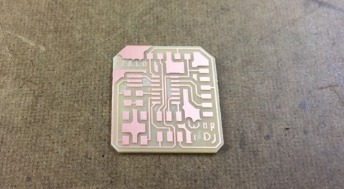
... this beatiful PCB
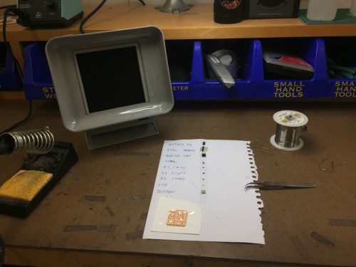
Getting ready to stuff the board ...
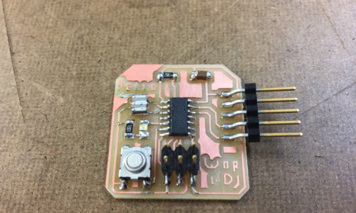
... and here it is the result. I had a hard time with soldering the crystal, but it worked!.
Programming the board (finally!)
NOW, I thought this was gonna be quick and easy. It's actually quick and easy, but it took a while until I learnt how...
I followed this high-low tech's tutorial for programming the ATtiny44 using Arduino IDE (along with a ton of help from Paloma and Dalma). Actually, this was the first time I programmed anything using it. Lucky for me, I had my USBTiny ready from last week! For some reason I had to connect and disconnect it a couple of times until it worked (...CS mysteries).
I started with the simple blink example from Arduino. And here it is the video:
Then, I used Jaclyn's modified code for testing the button. Note that my LED and button pins were 7 and 8, respectively (they correspond to PB2 and PA7 in my schematic). And it worked! Well, only when Dalma touched it. For some reason it didn't always work when I pressed it...(weird)
It also worked under situations where it shouldn't have to. Like when the board was touched at the back...(still weird)
So I decided to remove the button. And it still worked under some other (weird) situations, like when I touched the pads directly:
Or when I placed it on top of the vynil cutter:
But didn't work on top the the bench...
So I did some research. And it seems that I was missing a pullup resistor. Actually, Jaclyn explains it very well in her website... I was not sure where the resistor had to go, so I removed some part of my trace...
Peeling some traces off in order to install a resistor
At the end I figured out that I needed something like this (again, details are well explained in Jaclyn's):
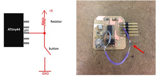
Pullup resistor
And here the video!!!
At the end of all this board debugging, I was told that I could have done the exact same thing just by changing pinMode(buttonPin, INPUT) by pinMode(buttonPin, INPUT_PULLUP) ... and Arduino IDE would have internally managed the pullup resistor... Anyway... at least I learnt something new
Next steps
After all, I enjoyed this week project. Now, I'd like to build another board, but this time with an RGB LED (since I may use those in my final project). What I want to do is a color timer: while you push the button, it will count from 1 to 7 in color, i.e. Red, Green, Blue, Red+Green (brown), Red+Blue (magenta), Green+Blue (cyan), Red+Green+Blue (white). I run out of time, but here it is the design:
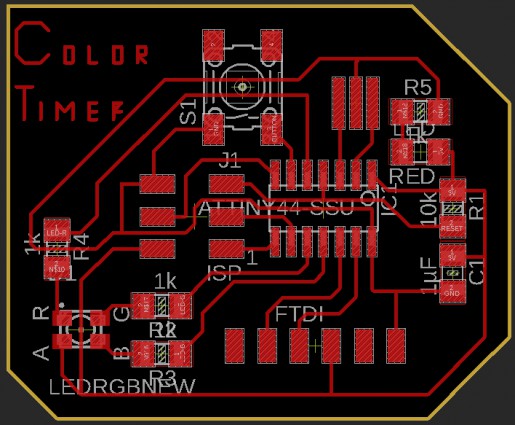
Next project: color timer
Also, for next week I want to improve my video skills: editing, changing resolution and embedding them directly into teh website (no youtube help!)
Files